Aquacal Pool Pilot Digital Nano User manual

INSTALLER: This Document is Purchaser’s Property and is to remain with the Equipment Owner
LTP0086 Rev-1C 07/28/2015
Pool Pilot®
Digital Nano/Nano+
Digital Nano Models: 75040, 75040-xx, 75041 and 75041-xx
Manifold: 94105
Cell: RC35/22
Digital Nano+Models: 75042, 75042-xx, 75043 and 75043-xx
Manifold: 94106
Cells: RC35/22 or RC28
Owner’s Manual
Installation / Operation
This manual covers the installation
and operation of Digital Nano and
Digital Nano+Chlorine Generators
Important!
Read This Manual And Product
Labels Before Installing Or
Operating This Equipment

i
TABLE OF CONTENTS
SECTION 1 - FACTORY CONTACT INFORMATION...........................................................................................1
SECTION 2 - SAFETY INFORMATION ................................................................................................................1
SECTION 3 - OWNER QUICK START & RUN.....................................................................................................3
3.1 How Your Digital Nano/Nano+Works ............................................................................................................3
3.2 Control Overview ............................................................................................................................................4
3.2.1 Up and Down Arrows...................................................................................................................4
3.2.2 The Boost Button ......................................................................................................................... 4
3.2.3 Menu and Select Button...............................................................................................................4
3.2.4 Check System Light and Audio Alarm .........................................................................................4
3.3 Normal Display................................................................................................................................................5
3.4 Water Balance & Chemistry Recommendations ............................................................................................5
SECTION 4 - SPECIFICATION AND APPROVALS.............................................................................................6
4.1 Specifications..................................................................................................................................................6
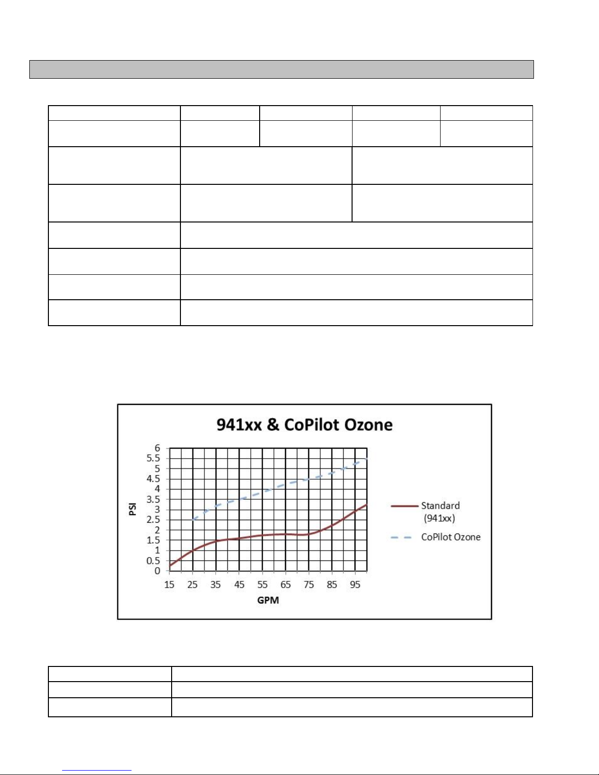
4.2 Manifold Pressure Drop Versus Flow .............................................................................................................6
4.3 Agency Approvals...........................................................................................................................................6
SECTION 5 - FEATURES......................................................................................................................................7
5.1 Patented Temperature Compensation............................................................................................................7
5.2 Water Manifolds Assemblies - Available Options...........................................................................................7
5.2.1 Automatic-Flow Bypass Manifold Assembly (#94105 and #94106) ............................................8
5.2.2 CoPilot Manifold Assembly.......................................................................................................... 8
SECTION 6 - MAINTENANCE...............................................................................................................................9
6.1 Fuse Location and Ratings.............................................................................................................................9
6.2 Removing / Inspecting / Cleaning Tri-Sensor...............................................................................................10
6.2.1 Tri-Sensor Assembly Overview..................................................................................................10
6.2.2 Inspect Tri-Sensor......................................................................................................................10
6.2.3 Cleaning Tri-Sensor...................................................................................................................11
6.2.4 Test Tri-Sensor Flow Switch......................................................................................................11
6.3 Servicing the Cell..........................................................................................................................................12
6.3.1 Removal.....................................................................................................................................12
6.3.2 Visual Inspection........................................................................................................................12
6.3.3 Manual Cleaning........................................................................................................................13
6.3.4 Installing.....................................................................................................................................13
6.4 Winterizing ....................................................................................................................................................14
6.5 Spring Start-up..............................................................................................................................................14
SECTION 7 -PROGRAMMING...........................................................................................................................15
7.1 Control Panel................................................................................................................................................15
7.1.1 Button Overview.........................................................................................................................15
7.1.2 Menu Button...............................................................................................................................15
7.1.3 Display Overview .......................................................................................................................15
7.2 Menus ...........................................................................................................................................................16
7.3 Basic Operational Programming...................................................................................................................16
7.3.1 Adjusting the Chlorine Output %................................................................................................16
7.3.2 Boost or Super Boost.................................................................................................................17
7.3.3 Chlorine Mode............................................................................................................................17
7.3.4 Chlorine % Adjustment Procedure.............................................................................................17
7.4 Test Pool Pilot (Diagnostic Menu) ................................................................................................................18
7.5 View Setup....................................................................................................................................................18

ii TABLE OF CONTENTS
7.6 Review of Installer, Owner, & Maintenance Menu Programming.................................................................19
7.6.1 Pool Volume...............................................................................................................................19
7.6.2 Calibrating Salt...........................................................................................................................19
7.6.3 Select Language........................................................................................................................19
7.6.4 Calibrating Temperature ............................................................................................................20
7.6.5 Select Units................................................................................................................................20
7.6.6 Temperature...............................................................................................................................20
7.6.7 Set Reverse Time ......................................................................................................................20
7.6.8 Program Cell’s self-cleaning cycle.............................................................................................20
7.6.9 Force Reverse:...........................................................................................................................21
7.6.10 Audio Alarm:.............................................................................................................................21
SECTION 8 -INSTALLATION.............................................................................................................................22
8.1 Basic System Overview................................................................................................................................22
8.2 Before Installing ............................................................................................................................................23
8.3 Parts..............................................................................................................................................................23
8.4 Installation Steps...........................................................................................................................................24
8.5 Plumbing Requirements................................................................................................................................24
8.5.1 Plumbing the Manifold Assembly...............................................................................................24
8.6 Mounting the Digital Nano/Nano+.................................................................................................................25
8.7 Electrical........................................................................................................................................................26
8.7.1 Electrical Connections................................................................................................................26
8.7.2 AC Input Voltage........................................................................................................................26
8.7.3 Low Voltage Wiring....................................................................................................................26
8.7.4 Low-Voltage Cable Connections at Control Center...................................................................27
8.7.5 Grounding and Bonding.............................................................................................................27
8.7.6 Connecting to an External Timer or Controller ..........................................................................27
8.8 Preparing the Pool Water..............................................................................................................................28
8.8.1 Steps to Prepare Water..............................................................................................................28
8.8.2 Calculating Pool Volume............................................................................................................28
8.8.3 Adding Salt.................................................................................................................................29
8.9 Programming at Installation..........................................................................................................................30
SECTION 9 - TROUBLESHOOTING...................................................................................................................31
SECTION 10 - REFERENCE.................................................................................................................................36
10.1 Basic Water Chemistry ...............................................................................................................................36
10.1.1 Chlorine....................................................................................................................................38
10.1.2 pH.............................................................................................................................................38
10.1.3 Total Alkalinity..........................................................................................................................38
10.1.4 Calcium Hardness....................................................................................................................38
10.1.5 Cyanuric Acid...........................................................................................................................38
10.2 Using the Saturation Index .........................................................................................................................39
10.3 Salt Addition Chart......................................................................................................................................39
10.4 Declaration of Conformity ...........................................................................................................................41
10.5 FCC Compliance.........................................................................................................................................41

Page 1
SECTION 1 - FACTORY CONTACT INFORMATION
If you should need to call AquaCal AutoPilot, Inc. for questions, services, or parts, please have your
model and serial numbers available. Please also have the name of your installer and date of your
equipment’s installation. If you have questions, please refer to our web site for the latest manual
revisions, additional information, and helpful service advice.
Web
www.AutoPilot.com
Power Supply Serial
Phone
(727) 823-5642
8-5 pm, Est., M-F
Cell Serial
Fax
(727) 821-7471
Tri-Sensor Serial
Address
AquaCal AutoPilot, Inc.
2737 24th Street North
St. Petersburg, Florida 33713
USA
Installer
Install Date
SECTION 2 - SAFETY INFORMATION
For personal safety, and to avoid damage to equipment, follow all safety instructions displayed on the
equipment and within this manual. Repair and service of your Digital Nano/Nano+must be performed
by qualified service personnel. Should you suspect your chlorine generator is not performing properly,
refer to the section in this manual entitled: "Troubleshooting," to determine if a call for service is
required. Warranties will be voided if the Digital Nano/Nano+has been improperly installed. Failures to
properly operate, maintain, or repair the Digital Nano/Nano+will void factory warranty.
Throughout this manual safety signals are placed where particular attention is required. Please note
"WARNING" signals relate to personal safety, while "CAUTION” signals promote avoiding damage to
equipment.
Follow all state, provincial and NEC (National Electrical Codes) and applicable CEC (Canadian
Electrical Codes) unless local guidelines supersede. When installing and using your Digital
Nano/Nano+, basic safety precautions must always be followed, including the following:
WARNING - Failure to heed the following may result in injury or death.
RISK OF ELECTRICAL SHOCK - Disconnect all AC power when installing or servicing
this system. Follow all state, local, and National Electrical Code(s) (provincial and
Canadian Electrical Code(s) if applicable). Use copper conductors only.
RISK OF ELECTRICAL SHOCK - Digital Nano/Nano+contains no Owner-repairable
components. Repairs must not be attempted by untrained and/or unqualified individuals.
If service is deemed necessary, contact installing dealer or AquaCal AutoPilot Customer
Support.
RISK OF ELECTRICAL SHOCK - A bonding lug has been provided on the outside of the
Digital Nano/Nano+. This lug permits the connection of a No. 8 AWG (8.4 mm2) solid
copper-bonding conductor (No. 6 AWG in Canada). Make this connection between the
Digital Nano/Nano+and all other electrical equipment and exposed metal within 5-feet
(1.5 m) of the Digital Nano/Nano+. All field-installed metal components (such as rails,
ladders, drains, etc.) within 10-feet of the pool, spa, or hot tub, must be bonded to the

Page 2
equipment grounding bus using copper conductors not smaller than No. 8 AWG
(8.4mm2) (No. 6 AWG in Canada).Maintain water chemistry in accordance with
manufacturer’s instructions.
RISK OF ELECTRICAL SHOCK - Digital Nano/Nano+configured to 115 Vac must be
installed at least 10 feet (3 m) from the pool or spa wall. Digital Nano/Nano+configured
to 230 Vac must be installed at least 5 feet (1.5m) from the pool or spa wall.
RISK OF ELECTRICAL SHOCK - A disconnect device incorporated into the fixed wiring
must be included in the supply circuit (such as a time clock, relay, or circuit breaker).
RISK OF ELECTRICAL SHOCK - Connect only to a branch circuit protected by a
ground-fault circuit-interrupter (GFCI). Contact a qualified electrician if you cannot verify
that the circuit is protected by a GFCI.
RISK OF ELECTRICAL SHOCK - Digital Nano/Nano+must be connected only to a
supply circuit that is protected by a ground-fault circuit-interrupter (GFCI). The GFCI
must be tested on a routine basis. To test, push the GFCI test button. Power should be
interrupted. Push the reset button. Power should be restored. If the GFCI fails to operate
in this manner, it is defective.
RISK OF ELECTRICAL SHOCK - If the ground-fault circuit-interrupter (GFCI) interrupts
power to the equipment without the test button being pushed, a ground current is flowing
with a possibility of an electrical shock. Do not use equipment. Disconnect the
equipment and have the problem corrected by a qualified service representative before
using.
CHEMICAL HAZARD - To avoid damaging splashes, always add acid to water, never
water to acid. Wear safety glasses and use other appropriate personal protection
equipment.
CHEMICAL HAZARD - Always follow the instructions on the manufacturer's label
whenever handling or using chemicals.
CHEMICAL HAZARD –Heavy pool (or spa) usage and higher temperatures may require
a higher chlorine output in order to maintain proper free available chlorine residuals.
WATER CHEMISTRY SAFETY - Improper water chemistry can present a serious health
hazard. The proper residual chlorine level and water chemistry must be maintained. The
addition of certain pool maintenance chemicals can reduce the effectiveness of chlorine.
Maintain Pool / Spa water per standards detailed later in this manual.
COMBUSTIBLE HAZARD –The AquaCal AutoPilot Digital Nano/Nano+is equipped with
an electronic flow switch that automatically turns the unit off in the event of a “low water
flow” situation. Do not tamper in any way with this safety feature.
PERSONAL SAFETY HAZARD –To reduce the risk of injury, do not permit children to
operate this device.
RISK OF CHILD DROWNING OR INJURY - Children must be closely supervised at all
times around pool or spa equipment.
CAUTION - Failure to heed the following may result in equipment damage.
The AquaCal AutoPilot Digital Nano/Nano+must be installed and operated as specified.
Failure to do so will void the equipment warranty.
To permit proper air circulation, the Digital Nano/Nano+must be mounted at least 1-foot
(30 cm) above ground level or any other cooling obstruction.
Special measures are required in the event of freezing conditions. Your Digital
Nano/Nano+may be damaged if measures are not taken in advance of freezing

Page 3
conditions. Equipment damage due to freezing conditions is NOT covered under the
equipment warranty.
Do not use a pool cleaner or vacuum head with wheels, as wheels can leave track
marks on newly-plastered pools. Do not allow Granular salt to pile up in one location,
without brushing, as staining may occur.
Excessively high chlorine levels can cause premature cell failure and corrosion damage
to pool fixtures and equipment.
For maximum cell life, maintain water in a balanced condition. Water maintained in a
scaling condition will shorten cell life and may render the Digital Nano/Nano+
inoperative. Damage and/or service calls, caused by improper water balance, will NOT
be covered under the equipment warranty.
Scraping or scratching the titanium blade’s edge or surface will damage the blade
catalyst coating and cause premature failure of the cell... warranty will be voided. Never
use any sharp or metallic objects to remove scale.
Reduced polarity reversing cycle times will reduce cell life, and should only be used due
to uncontrollable scale formation on the cell. ALWAYS test and adjust water balance,
before attempting scale control via shortening reverse period.
The Tri-Sensor should not be pulled out at an angle, or the flow paddle or flow post may
be damaged. SAVE THESE INSTRUCTIONS
SECTION 3 - OWNER QUICK START & RUN
1) Balance the water chemistry according to the water chemistry parameters on page 5 and salt
recommendations on page 29. The Digital Nano/Nano+may be started immediately. The salt
reading, however, may initially be inaccurate until the circulation pump has been run for 24
hours to fully dissolve newly added salt.
2) Use the “UP” and “DOWN” arrow buttons to set the chlorine percentage to 50%.
3) During the first two weeks, test the water chemistry parameters every 3-4 days. Adjust chlorine
percentage as needed.
4) Once ideal chlorine percentage has been determined, follow normal maintenance procedures.
3.1 HOW YOUR DIGITAL NANO/NANO+WORKS
The Digital Nano/Nano+is designed to handle the purification needs of residential swimming pools and
spas. The amount of chlorine required for proper sanitization will vary based on the pool size and
various factors such as water temperature, bather load, exposure to direct sunlight, and special water
features.
The system requires a low concentration of dissolved salt (sodium chloride) in the water. The salt
concentration level is normally maintained below the taste threshold. The Digital Nano/Nano+
automatically converts the salt into chlorine, which your pool/spa requires to remain sanitized and algae
free. The chlorine reverts back to salt after treating the water. Since the salt is constantly recycled,
there is minimal loss during a swimming season. However, salt can be lost due to filter backwashing,
rain water overflow, leaks, or bather splashing/carry out... but not through evaporation.
The water circulation pump must be operating for your Digital Nano/Nano+to produce chlorine, so run
time is one of several key components to maintaining the proper sanitizer levels. Most installations
require a minimum of eight (8) hours-per-day pump run time to properly filter and sanitize the water.

Page 4
3.2 CONTROL OVERVIEW
The following is a brief explanation of owner or operator control options. For full features of the Owner
Options Menu, please see page 19. The MENU button is pressed to obtain access to the Owner
Options Menu.
Please Note: This section assumes the installer has already programmed the system for
specific site parameters, has established proper water balance, and has pretreated water to 1 -
3 ppm (mg/L) chlorine.
Attention Owner: Should Centigrade vs. Fahrenheit, choice of language, or other owner options
require modification, please refer to the programming information located on page 19.
See: Menu Button and Owner Options.
3.2.1 Up and Down Arrows
Use the UP and DOWN arrows to control the chlorine output level, then press the SELECT
button to save the value chosen. With a properly prepared pool, the recommended starting
output level is 50%.
Upon initial start-up, check sanitizer every 3-4 days and make small output level adjustments as
necessary to maintain 1-3 ppm (mg/L) free chlorine levels. Keep in mind, your Digital
Nano/Nano+does not directly measure or regulate the sanitizer levels in your pool. Rather, the
owner / operator will need to periodically test the water to determine the current chlorine level,
and adjust the output setting as needed.
After the chlorine output level is “tuned in,” the unit will automatically make fine output
adjustments as the water temperature fluctuates. This temperature compensation feature will
adjust output depending on water temperature. See page 7 for more information concerning the
patented temperature compensation feature.
Please Note: The optimum output setting will vary based upon pool size, location, exposure to
sunlight, number of users, vegetation around the pool, water balance practices, and pump run
time. Your installer should have already taken these factors into consideration when performing
installation programming. Therefore, your adjustments, at this point, should be relatively minor.
3.2.2 The Boost Button
The BOOST button increases output to 100%. Use this feature when a heavier than normal
bather load is anticipated.
Press BOOST once ............................ = 24 Hour Boost
Press and hold BOOST for 8 seconds = 72 Hour Boost
Press BOOST a second time .............. = Deactivate Boost
3.2.3 Menu and Select Button
This allows access to the “Test,” “Setup,” “Owner Option,” “Maintenance,” and “Installer” menus.
The “SELECT”button allows the operator to choose program menu options. The owner /
operator should not normally need to access these features on a regular basis.
Consult “Programming” section, or contact factory customer support for additional information.
3.2.4 Check System Light and Audio Alarm
The CHECK SYSTEM light will flash to warn the unit may need attention. A warning message will
also be displayed. If enabled, an audio alarm* may also be heard when the system light is flashing.
Unless deemed a normal condition, per below, see troubleshooting section.
Flashes red when pump is off / water flow is insufficient. (It is normal for the light to flash if
the circulation pump is off)
Flashes when salt is low

Page 5
Flashes when water temperature exceeds 125°F, or drops below 10°F
Note: When enabled, an audio alarm will sound due to any of the above three (3) conditions. If
water flow ceases (or falls below minimum acceptable levels) the alarm will automatically silence
after 10 minutes. To enable or disable audio alarm, see “Audio Alarm” in programming instructions.
3.3 NORMAL DISPLAY
Chlorine Output level..............in 1% increments, from 0% to 100%
Water Temperature................in Fahrenheit or Celsius
Cell Status..............................ON or OFF
Check System Light ...............OFF when operating normally
Check System Light ...............Normally blinking when circulation pump is off and supply power to
the controller remains on.
3.4 WATER BALANCE & CHEMISTRY RECOMMENDATIONS
Proper water balance is critical to the operation of your Digital Nano/Nano+.
Conditions such as high pH levels, low Cyanuric acid (stabilizer) levels, or other factors causing
unbalanced water, will mask the sanitizer production of your Digital Nano/Nano+.
Please note the following recommended water chemistry parameters are for residential pool/spa
applications only. Follow local regulatory guidelines for any commercial pool applications.
POOL
SPA
PARAMETER
UNITS
MIN
IDEAL
MAX
MIN
IDEAL
MAX
Free Chlorine
ppm (mg/L)
1.0
2.0 - 4.0
5
2.0
3.0 - 4.0
10
Combined Chlorine
ppm (mg/L)
0.0
0.0
0.2
0.0
0.0
0.5
pH
7.2
7.2 -7.8
7.8
7.2
7.2 -7.8
7.8
Total Alkalinity
ppm (mg/L)
60
80 - 100
180
60
80 - 100
180
Calcium Hardness
ppm (mg/L)
150
200 - 400
1000
100
150 - 250
1000
Salt
ppm (mg/L)
2000
2500 - 3500
**
2000
2500 - 3500
**
Cyanuric Acid (stabilizer)
ppm (mg/L)
0
30 - 50
***
0
30 - 50
***
Table 1
** Typically 6000 ppm (mg/L) or less is recommended; unit can operate with levels as high as
35,000+ ppm (mg/L).
*** This is dictated by state or local codes but is typically 100 ppm (mg/L).
See “Basic Water Chemistry” on page 36 and “Using the Saturation Index” on page 39 for further
information concerning pool/spa water chemistry maintenance requirements. Or refer to the
Troubleshooting section in the back of this manual.

Page 6
SECTION 4 - SPECIFICATION AND APPROVALS
4.1 SPECIFICATIONS
SPECIFICATION
75040, 75040-XX
75041, 75041-XX
75042, 75042-XX
75043, 75043-XX
Input Power
110-120 Vac
2.0 A
220-240 Vac
1.0 A
110-120 Vac
2.0 A
220-240 Vac
1.0 A
Maximum Chlorine Output
RC35/22
0.8 lb. /day (15.11 g/hr.)
0.8 lb. /day (15.1 g/hr.))
Maximum Chlorine Output
RC28
not applicable
1.06 lb. /day (20.0 g/hr.)
Minimum Flow Rate
for 941xx
15 gpm (76 L/min)
Minimum Flow Rate for
Co-Pilot Ozone
25 gpm (95 L/min)
Maximum Flow Rate
100 gpm (379 L/min)
Maximum Operating
Pressure
85 psi
Table 2
4.2 MANIFOLD PRESSURE DROP VERSUS FLOW
The following chart shows pressure drops versus flow for all Digital Nano/Nano+ manifolds. The
optional CoPilot Ozone manifold is also listed.
Table 3
4.3 AGENCY APPROVALS
Tested to conform to the following specifications:
APPROVAL
DESCRIPTION
UL1081
Standard for Safety for Swimming Pool Pumps, Filters, and Chlorinators.
CAN / CSA-E60335-1
Safety of Household and Similar Electrical Appliances.

Page 7
SECTION 5 - FEATURES
Patented temperature compensation for chlorine output control.
Programmable microprocessor control.
Multi-language digital display (English, Spanish, French and either Italian or Czech).
Digitally controlled power to the cell.
Tri-Sensor circuitry to monitor water flow, water temperature, and salt level. Calculates and
provides recommended salt addition amounts required to maintain the recommended 3000 ppm
(mg/L) salt concentration level.
5.1 PATENTED TEMPERATURE COMPENSATION
WARNING - Failure to heed the following may result in permanent injury or death.
Pool or Spa water temperature should not exceed 104°F (40°C).
The Tri-Sensor temperature sensor works in conjunction with the chlorine % feature to automatically
adjust chlorine output based upon changes in water temperature. The automatic compensation feature
operates between 55°F and 125°F (13°C - 52°C).
As water temperature falls below 65°F (18°C), the controller will activate a high chlorine percent
lockout, and may not allow chlorine adjustments up to 100%. This feature prevents the controller from
over-driving the cell under colder temperatures, thus preventing premature cell wear.
At 55°F (13°C) or colder water temperatures, the controller will adjust to a fixed 1% output, thus
preventing over-chlorination and premature cell failure.
As the water temperature rises above set point, the controller will adjust at 5% per °F up to 100%, thus
preventing under-chlorination during warmer water temperatures.
5.2 WATER MANIFOLDS ASSEMBLIES - AVAILABLE OPTIONS
CAUTION - Failure to heed the following may result in equipment damage.
The Digital Nano manifold may only use the RC35/22 cell. The Digital Nano+
may use either the RC35/22 or RC28 cell.
The Digital Nano uses the patented automatic-flow bypass manifold assembly (models 94105,
94105M). The Digital Nano should ONLY use the RC35/22 cell.
The Digital Nano+ uses the patented automatic-flow bypass manifold assembly (models 94106,
94106M) with an RC28 cell. The Digital Nano+ may also use an RC35/22 cell but the maximum
chlorine output will be lower. See the Specifications table in section 4.1 on 6.
The CoPilot manifold assembly comes with an automatic-flow bypass, check valve assembly and
ozone injector venturi assembly.

Page 8
5.2.1 Automatic-Flow Bypass Manifold Assembly (#94105 and #94106)
This AquaCal AutoPilot patented manifold is connected into
the plumbing after all other equipment. Water from the
pool/spa is moved though the manifold by the circulation
pump. This patented manifold uses four key components:
The Tri-Sensor provides data (from electronic sensors) to the
Digital Nano/Nano+for monitoring water flow, water
temperature, and salt concentration level. The Digital
Nano/Nano+uses this data to determine if conditions are safe
for the cell to operate; the signal read from the temperature
sensor allows the automatic temperature compensation feature
to function.
The Cell (RC35/22 or RC28) receives power from the Digital
Nano/Nano+and converts the salt contained in the water to
chlorine.
The Strainer Screen prevents debris in the water from entering the Tri-Sensor or cell, and requires
periodic inspection and cleaning.
The Bypass Check Valve allows the water flow rate to be slowed and optimized through the cell,
while permitting the pump to continue to circulate water to-and-from the pool/spa at full flow rates.
The reduced water flow through the cell results in a more efficient "Super-Chlorination” effect,
resulting in improved overall sanitization.
5.2.2 CoPilot Manifold Assembly
The CoPilot system is designed to be used in conjunction
with the Digital Nano/Nano+ to reduce chlorine demand
and extend cell life. This system is also sold separately as
an upgrade to existing Digital Nano/Nano+systems.
The manifold is connected into the plumbing after all other
equipment. Water from the pool/spa is moved though the
manifold by the circulation pump:
The Tri-Sensor provides data (from electronic sensors) to
the Digital Nano/Nano+for monitoring water flow, water
temperature, and salt concentration level. The Digital
Nano/Nano+uses this data to determine if conditions are
safe for the cell to operate; the signal read from the
temperature sensor allows the automatic temperature compensation feature to function.
The Cell (RC35/22 or RC28) receives power from the Digital Nano/Nano+and converts the salt
contained in the water to chlorine.
The Strainer Screen prevents debris in the water from entering the Tri-Sensor or cell, and requires
periodic inspection and cleaning.
The Bypass Check Valve allows the water flow rate to be slowed and optimized through the cell,
while permitting the pump to continue to circulate water to-and-from the pool/spa at full flow rates.
The reduced water flow through the cell results in a more efficient "Super-Chlorination” effect,
resulting in improved overall sanitization.
The Ozone Venturi Injector introduces ozone directly into the water before the Digital Nano/Nano+
cell. The ozone venturi injector is connected to the CoPilot via an Ozone Check Valve and Tube
Assembly (not shown).
Tri-Sensor
Ozone Venturi
Injector
Cell
Bypass Check Valve
Strainer
Screen

Page 9
SECTION 6 - MAINTENANCE
6.1 FUSE LOCATION AND RATINGS
WARNING - Failure to heed the following may result in permanent injury or death.
ELECTRICAL SHOCK HAZARD –Turn off the electrical power to unit before
servicing.
To inspect or service fuse, disconnect power and remove power center cover (see below for location of
fuse).
Ratings
BOARD
FUSE SPECIFICATION
DESCRIPTION
Main Power Board (Factory set as115 Vac)
75040, 75042, 75040-xx, 75042-xx
250 Vac 2 Amp Slow Blow
Main AC Power Fuse
Main Power Board (Factory set as 230 Vac)
75041, 75043, 75041-xx, 75043-xx
250 Vac 1 Amp Slow Blow
Main AC Power Fuse
Location of Fuse
Fuse

Page 10
Tri-Sensor Assembly
Flow Paddle
Salt Sensor Blades
Temperature
Sensor Post
Tri-Sensor
O-Ring
Indicator of
Flow Direction
6.2 REMOVING / INSPECTING / CLEANING TRI-SENSOR
6.2.1 Tri-Sensor Assembly Overview
The Tri-Sensor Assembly is used to measure water flow, salt level, and water temperature.
Note: The use of high strength magnet devices in the close proximity of the Tri-Sensor can cause
the flow switch to function incorrectly.
When the water flow reaches a minimum flow
rate of 15 gpm (76 L/min), the flow paddle
magnet closes a micro-switch monitored by the
Digital Nano/Nano+. The CoPilot Ozone
manifold requires a minimum flow of 25 gpm
(95 L/min).
The Digital Nano/Nano+uses dedicated salt
sensor blades to measure the level of salt in
the water.
The Digital Nano/Nano+uses the temperature
sensor to determine water temperature. This
measurement is required for the Patented
Automatic Temperature Compensation feature
to automatically adjust chlorine output as water temperature varies. Less chlorine is needed in
cold water, so chlorine output is automatically reduced as water temperature drops (avoiding
excess chlorine production). Conversely, more chlorine is needed in warmer water, and
production is automatically adjusted higher as water temperatures increase.
Please note - the Tri-Sensor normally does not require maintenance or cleaning.
WARNING - Failure to heed the following may result in permanent injury or death.
CHEMICAL HAZARD - To avoid damaging splashes always add acid to water,
never water to acid. Wear appropriate personal safety protection including safety
glasses when using pool chemicals.
CAUTION - Failure to heed the following may result in equipment damage.
The Tri-Sensor should not be removed from manifold at an angle, or the flow
paddle and/or flow post may be damaged.
6.2.2 Inspect Tri-Sensor
1) Disconnect the Tri-Sensor cable from the power center.
2) Remove the two (2) screws retaining the Tri-Sensor in the Tee joint of the Manifold.
Note the orientation of the Direction of Flow Tab. The Tri-Sensor must be installed in the
same orientation when it is reinstalled or replaced.
3) The Tri-Sensor can now be pulled out of the Tee.
Firmly grip the Tri-Sensor assembly (this is typically done with a large pair of channel lock
pliers).
Twist the Tri-Sensor back-and-forth while simultaneously pulling the Tri-Sensor straight out
of the Tee joint.
4) Check the Tri-Sensor assembly for any damage to the plastic housing and replace if needed.
5) Inspect the following on the flow switch: verify the thin metallic paddle is straight and free from
erosion; verify the plastic post is straight and free of cracks. Do not twist or bend the paddle or the
plastic post.
Figure 1

Page 11
6) Inspect the two salt sensor blades. The blades should not have any mineral deposits (scale) or
other debris on them.
7) Do not use any metallic objects to scrape the blade surfaces or you will remove or damage the
blade sensor coating.
6.2.3 Cleaning Tri-Sensor
If required, you can remove a calcium scale buildup by creating a solution of water and muriatic acid
as follows. Do not use any metallic objects to scrape the blade surfaces or you will remove or damage
the blade sensor coating.
1) Mix the solution in a small container tall enough to cover the sensor blades. DO NOT add water
to acids; always add acid to water in container.
2) Mix one (1) part Muriatic Acid into four (4) parts water.
3) Immerse the salt sensor blades in the solution for up to 15 minutes. An effervescing action
indicates the calcium is being dissolved from the blades.
4) Rinse with fresh water and re-inspect. Repeat the acid treatment as necessary until all scale
has been eliminated.
6.2.4 Test Tri-Sensor Flow Switch
WARNING - Failure to heed the following may result in permanent injury or death.
Do NOT operate system with a faulty water flow switch.
The flow switch is a critical equipment protection device to prevent damage to the cell or system.
When water flow has stopped, power to the cell is automatically turned OFF. It is important to verify
the proper operation of the Tri-Sensor’s water Flow Switch protection device.
The following procedure can be used to verify the proper operation of the flow switch, or to flush
debris from the Bypass Valve.
1) Turn off circulation pump.
2) Slightly loosen the union nut just below the cell
on the side of the manifold that does not contain
the filter screen.
3) Completely loosen the manifold union nut that
contains the filter screen and pivot the manifold
to gain access to the filter screen.
4) Remove the screen. Clean the screen if dirty.
5) If the screen was dirty, then the system may
need to be purged to remove excess debris.
Leave the manifold off and run the pump for a
few seconds until clear.
6) Wrap the strainer screen securely with a small
piece of plastic wrap (saran wrap, food wrap or
zip lock bag) as indicated in the diagram, place it
back in the union.
7) Tighten the two unions that were loosened.
8) Turn on the pump and the Digital Nano/Nano+. The plastic will stop water flow to the flow
switch, which is part of the Tri-Sensor that is located in the upper portion of the manifold. All
water will be forced through the Bypass Valve. This action will normally flush out any small bits
of debris trapped in the Bypass Valve.)
STRAINER SCREEN SHOWN
TEMPORARILY WRAPPED IN PLASTIC
Figure 2

Page 12
9) The Digital Nano/Nano+should detect a low water flow at the Tri-Sensor, and activate the red
“Check System”light. The Digital Nano/Nano+will also display the message “Chlorine off
Check flow.”
10) If the Digital Nano/Nano+did not display this warning, check the Tri-Sensor cable connections
and inspect and clean the Tri-Sensor as outlined on page 11. If the warning message still
does not appear, then turn the Pool Pilot off and contact the factory or your local dealer for
assistance.
11) Turn the pump off.
12) Loosen the unions.
13) Remove the plastic wrap and replace the strainer screen.
14) Resume normal operation.
6.3 SERVICING THE CELL
The cell may require removal for periodic visual inspections, or for servicing when debris or calcium
mineral deposits develop. The need to inspect and service the cell is indicated by the “Check System”
light flashing and/or a screen message, “Low flow; “Error purifier off” or “Check/clean cell.”
6.3.1 Removal
The cell is installed with Unions on each end to allow quick and easy installation and removal.
1) Turn off pump and shut off all power.
2) Detach the cell cable from the cell.
3) Unscrew the unions at both ends of the cell.
4) Slide the cell out of the Manifold Assembly.
Figure 3
6.3.2 Visual Inspection
Your Digital Nano/Nano+is designed to automatically self-clean calcium
scale build up that may form on the blades during normal operation.
However, unbalanced water chemistry can cause a heavy scale build up
exceeding self-cleaning capabilities... thus; periodic manual cleaning
may be necessary. The simplest way to avoid this extra work is to
maintain the water chemistry at the levels recommended.
1) The cell titanium blades, seen inside the cell body, should be
straight and clear of any debris on the ends or between the
blades.
Figure 4
End view of the cell looking
at the blades
Models 94105 / 94106
Manifolds
Unions

Page 13
2) White flaky or crusty calcium build up on the edge or between the blades will shorten the life of
the cell. If required, clean the cell immediately, and determine the cause of scaling. See “Basic
Water Chemistry,” and “Using the Saturation Index”.
6.3.3 Manual Cleaning
WARNING - Failure to heed the following may result in permanent injury or death.
CHEMICAL HAZARD - To avoid damaging splashes always add acid to water,
never water to acid. Wear safety glasses and use other appropriate personal
protection equipment.
CAUTION - Failure to heed the following may result in equipment damage.
Scraping or scratching the titanium blade’s edge or surface will damage the
blade catalyst coating and cause premature failure of the cell... warranty will be
voided. Never use any sharp or metallic objects to remove
scale.
1) Place a PLA0113 cell cleaning plug (AutoPilot accessory) on the end of the
cell as shown. A 1 ½” MPT clean out plug may also be used and can be
purchased in the PVC plumbing section at most pool supply or home
improvement stores.
2) Fill the capped cell with water 2 inches from the top of the cell blades.
3) Fill the rest of the cell with muriatic acid. This allows for an approximate 1-to-4
solution. Always add the acid to the water. If you do it the other way around, it
can cause the solution to spray back causing serious injury.
4) Allow the solution to sit in the cell for 20 minutes or until the acid stops
bubbling.
5) Safely dispose of the solution; pouring it into the pool is recommended.
6) Remove the cap and rinse the cell with light water pressure; re-inspect the
cell, and repeat acid cleaning if the cell is still scaled.
6.3.4 Installing
CAUTION - Failure to heed the following may result in equipment damage.
The Digital Nano system is to be used ONLY with an RC35/22 cell. Use of any
other cell may cause equipment damage and void warranty.
The Digital Nano+ system can be used with the larger RC28 or the smaller
RC35/22 cell (It is normally shipped with the RC28 cell).
CAUTION - Failure to heed the following may result in equipment damage.
Ensure that cell cable is fully mounted. Partially seated cable may result in
damage to cable or cell during operation.
CAUTION - Failure to heed the following may result in equipment damage.
The electrical terminals must be completely dry to avoid corrosion and failure of
the cell or cable.
1) Clean and dry the electrical terminals on the cell. The contacts must be completely dry to avoid
corrosion and failure of the cell or cable.
2) Ensure the union O-rings are in place; then place the cell into the manifold with cell pins pointed
upward. See Figure 3.
3) Tighten the unions by hand for a watertight seal.
PLA0113 cell
cleaning plug or
1.5” MPT Plug
Figure 5

Page 14
4) The cell cable has three (3) electrical contact terminals. The cell will have two (2) electrical
terminals. Position the cell plug so the two (2) open holes align with two mating terminals and
push gently, but firmly, to connect. Use the red weather plug (supplied) to seal the unused
contact in the cable.
5) Turn on the system.
6) Check for leaks and proper operation.
6.4 WINTERIZING
CAUTION - Failure to heed the following may result in equipment damage.
Special measures are required in the event of freezing conditions. The Digital
Nano/Nano+may be damaged if measures are not taken in advance of freezing
conditions. Equipment damage due to freezing conditions is NOT covered under
the equipment warranty.
During brief freezing conditions, allow the filtration system to run continuously throughout the freeze
period. Circulating (moving) water will not freeze.
In areas where freezing conditions are prevalent and sustained, the equipment must be winterized as
follows:
Drain all water from the Manifold Assembly (cell and Tri-Sensor), pump, filter, supply and return
lines prior to freezing weather.
The Digital Nano/Nano+power supply is not affected by the cold and does not need to be
removed.
6.5 SPRING START-UP
1. It is recommended the water be manually chlorine-shocked when first starting up the pool in the
springtime.
2. Test water, and add the appropriate chemicals to balance the pool water per the levels
recommended in this manual.
3. Be sure to check salt and Cyanuric acid (stabilizer), bringing those readings up to the
recommended levels.
4. It is also a good idea to inspect the cell, manifold screen, and test the Tri-Sensor flow switch;
clean and/or replace those items as necessary.

Page 15
SECTION 7 - PROGRAMMING
7.1 CONTROL PANEL
7.1.1 Button Overview
7.1.2 Menu Button
The MENU button is used to leave the normal operation mode and enter the program and diagnostic
modes. Use the UP/DOWN arrows and SELECT buttons to navigate through the menus and sub-
menus. Note: to permit quick access to features, some functions are accessed or programmed in
several menus.
Test Pool Pilot - displays various operating parameters and diagnostic results
View Setup - displays the programmed setup parameters
Owner Options - programs the primary operating parameters an owner would need to change
Maintenance Menu - tests and programs the primary features a service technician would need
to access when servicing the system
Installer Menu - program the initial system setup
SELECT Button
The SELECT button chooses the displayed menu option. For the Installer Menu, press and hold the
SELECT button for approximately 13 seconds to access this feature. The SELECT button also
temporarily disables the buzzer during an error display.
7.1.3 Display Overview
The first line of the display typically indicates Chlorine Output Level in percent, or whether the system
is in Boost or Super-Boost mode. The second line displays temperature in Fahrenheit or Celsius and
chlorine on/off mode. A small dot in bottom right corner indicates the self-cleaning forward/reverse
cycle.
Push UP or DOWN arrow to
do the following:
Sets Chlorine Level %*
Scrolls through Menus
and Sub-Menus
Increases or Decreases
programming values for
menus.
CHECK SYSTEM LIGHT:
Red LED flashes to warn
attention is required.
A warning message will
also be displayed.
If enabled, an audio alarm
may also be heard when
the system light is flashing.
Push BOOST:
Select to start 24 hour
boost mode.
Select and hold for eight
(8) seconds to start 72
hour boost mode.
Select again to cancel
boost mode.
Push MENU:
Leave normal operation and
access menus for programming
and diagnostics
Push SELECT
Chooses item currently
displayed.

Page 16
7.2 MENUS
7.3 BASIC OPERATIONAL PROGRAMMING
7.3.1 Adjusting the Chlorine Output %
Typically, once the initial setting is established, very little adjustment is needed. The chlorine % setting
refers to the amount of time the cell is energized within a 15 minute cycle. The system cycles on-and-
off, as indicated on the display's lower right display and “ON,” when generating chlorine. Higher
settings will generate more chlorine.
1) Press the UP/DOWN ( or ) arrow buttons to enter the chlorine adjustment mode.
Adjust the chlorine output percentage to the desired output: from 0% (off) to 100 %
(maximum output); then, press SELECT to default back to the normal display.
At startup of a new system, the standard output setting starting point is 50%.
Follow the instructions in the chart on page 36 to determine and correct chlorine% settings.
Example:
50% setting = 50% of 15 minutes or 7.5 minutes ON and 7.5 minutes OFF.
25% setting = 3.75 min ON, 11.25 min OFF
Once the percentage is set, the unit will implement the temperature compensation algorithm based on
current water temperature.
Test Pool Pilot
Salt
Salt Needed
Temperature
Cell V/A
Amp Hrs
View Setup
Software Version
Serial Number
Display Software Version
Power Level (Factory Set)
Audio Alarm On / Off
Pool Size
Reverse Time
Temp Adjust
Salt Adjust
Shutoff Temp
Max Onboard Temp
Owner Options
Select Language
Select Units
Temperature Unit
Audio Alarm
End Menu Mode
Maintenance Menu
Force Reverse
Set Reverse Time
Replace Cell
Calibrate Salt
Calibrate Temperature
End Menu Mode
Installer Menu
Select Language
Select Units
Temperature Unit
Set Pool Volume
Audio Alarm
Enable Demo
End Menu Mode
Main Menu
Test Pool Pilot
View Setup
Owner Options
Maintenance Menu
Installer Menu
End Menu Mode

Page 17
7.3.2 Boost or Super Boost
The Boost feature is used to increase the chlorine % from its normal setting to 100% for a cumulative
24 hour or 72 hour period. When the Boost period expires or is manually terminated the chlorine %
returns to its previous setting and normal operation.
Boost chlorine output to 100% for 24 hours... From the normal operation mode, press and
release the BOOST button. The display will flash: "Boost 24 hour ON," then “Boost hh” (with the
“hh” actually being the displayed hours remaining in the boost period).
Boost chlorine output to 100% for 72 hours... From normal operation mode, press and hold the
BOOST button until: “Boost 72 hour ON” is displayed; then release the BOOST button. Display
will show: “Boost” for approximately 8 seconds, after that: “Boost 72 hour ON” will display; then,
“Boost hh” (with the “hh” actually being the displayed hours remaining in boost period).
If an external time clock or controller turns off power to the Digital Nano/Nano+ while boost is
active, the boost timer is stored in memory and the boost time will resume countdown when
power is reapplied to the unit.
If water flow is stopped during a Boost cycle, chlorine generation will stop while there is no flow
but the Boost timer will continue to count down as long as the Digital Nano/Nano+has power.
To exit Boost or Super Boost mode and revert to normal operation:
Allow the Boost cycle to expire, or
Press BOOST at any time to manually deactivate Boost.
7.3.3 Chlorine Mode
The Digital Nano/Nano+will automatically display informative messages about the condition of the
Digital Nano/Nano+(Chlorine output %, water temperature, warning messages, etc.), and responds to
manual adjustment of chlorine % setting (as described below). The Digital Nano/Nano+will revert to
the normal display if there is no activity on the keypad for thirteen (13) or more seconds.
7.3.4 Chlorine % Adjustment Procedure
1) Balance water chemistry according to necessary water chemistry parameters. (See basic water
chemistry starting on page 36.) For new startups, if free chlorine level as tested is not at least 1
ppm (mg/L), add liquid chlorine to ensure 1 to 3 ppm (mg/L) free chlorine reading.
2) Add the proper amount of salt as indicated by the Digital Nano/Nano+(or as described on page
39), and run the circulation pump continuously for 24 hours allowing the salt to be fully mixed
and dissolved into the pool. If the salt level is too low, the Digital Nano/Nano+will provide a
warning, and will not generate chlorine until the minimum salt level has been reached.
3) Use the UP and DOWN arrow buttons to set the chlorine % to 50%, and then allow the pool to
operate normally.
For the first two weeks, test the water chemistry parameters every 3-4 days. Adjust chemicals as
needed to maintain correct water balance.
This manual suits for next models
1
Table of contents
Other Aquacal Water Filtration System manuals
Popular Water Filtration System manuals by other brands

Biosan
Biosan Labaqua Trace User instructions

SMC Networks
SMC Networks AFF70D Operation manual

Pentair
Pentair STA-RITE SAND DOLLAR Installation and user guide

Doulton
Doulton Ceramic Twin Undersink Installation & maintenance guide

Panasonic
Panasonic ET-RFC100 operating instructions

IGM
IGM LAGUNA AFlux 12 operating instructions