MPM 50 User manual

Miniature Plastic Molding
Affordable Injection Molding Machinery
Model #50 – Hydraulic Molding Machine
OVERMOLDING MANUAL
6750 Arnold Miller Pk y.
Solon, Ohio 44139
440-498-8465
Model #50
Overmolding Manual
Version 1.00
Miniature Plastic Molding

OVERVIEW
This manual is a supplement to the provided Operating Manual included ith the Model 50
injection molding machine. The information in this manual is in addition to the information
provided in the other manuals.
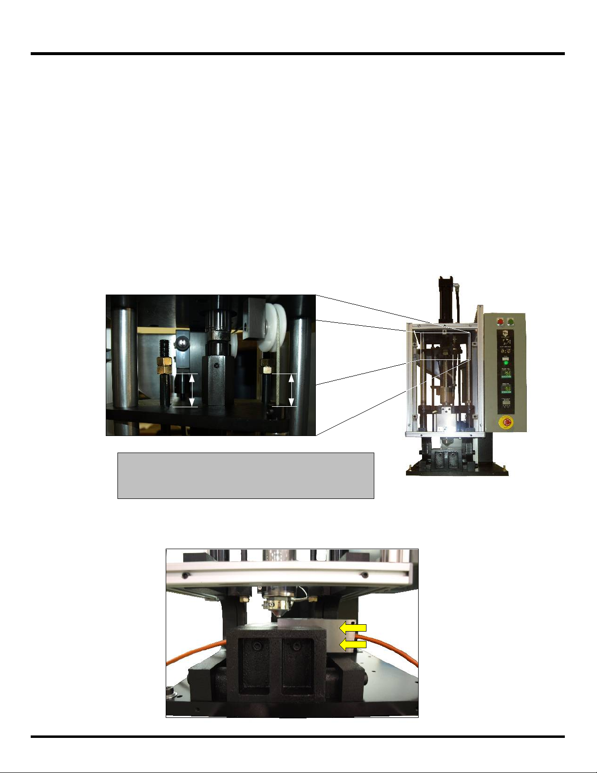
The Model 50 machines have an optional base kno n as a 'C' frame. The optional base
takes the typical machine's 'V' mold base and rotates it 90º. The lo er frame of the machine is
also shaped so that it leaves the front of the machine open. Thus, operators can perform molding
operations on long cables ithout having to feed the cable through the center of the machine.
The option as intended to allo the end-user to repair damaged cable jackets. The purpose of
this manual is to explain in more detail ho to operate a Model 50 machine ith the 'C' frame
option.
1
GENERAL SAFETY INFORMATION
(1) ALWAYS WEAR SAFE Y GLASSES hen running this or other types of machinery or
equipment. Make sure that the glasses are constructed of ANSI (American National Standards
Institute) approved material.
(2) Please READ HE PROVIDED MANUALS in their complete entirety before beginning any
ork on the machine. Failure to revie the provided manuals may result in damage to the
equipment or injury to the operator.
(4) ALWAYS SHUT OFF THE POWER TO THE MACHINE when performing maintenance tasks.
An emergency stop button is provided on the operator’s panel that requires re-setting to operate
again. This button should not be used for shutting down the machine for maintenance. To shut
off power to the machine, use the rotary disconnect located on the main electrical enclosure. The
disconnect is also equipped with a lock-out feature for servicing the machine.
(5) NEVER REACH INTO THE MACHINE ithout taking safety precautions. There are potential
pinch points, high temperatures and voltages that ould present hazards to the operator if the
machine ere used in a careless manner.
(6) NEVER have more than one person operating the machine at any time.
(3) NEVER OPERATE THE MACHINE WHILE GUARDS ARE REMOVED OR RENDERED IN-
OPERATIVE. The Model 50 machine does not contain a moving clamping mechanism, but there
are moving parts, heater bands, and electrical devices that become potential safety hazards if the
guards are removed or the machine is operated in a careless manner.
(7) MAKE SURE THE MACHINE'S STAND IS SECURE BEFORE OPERATING. The machine
typically comes with a stand equipped with casters. Before operating the machine, make sure the
pads on the casters have been lowered. Failure to do so could cause the machine to move
around in an unsafe manner during operation. If the machine is positioned that permits access to
the rear of the unit, additional barrier guarding must be provided to prevent access.
(8) NEVER LEAVE HE MACHINE’S HEA ERS ON FOR ANY EX ENDED LENG H OF IME
WHEN HE MACHINE IS NO BEING OPERA ED. It may overheat the material in the scre
barrel, possibly degrading it to the point here it could explode, expelling dangerous gases.

INTRODUCTION
'V' Mold for Overmolding Cables
Miniature Plastic Molding offers a 'V' mold designed to overmold damaged jackets on
cables. The mold contains a large pocket to surround the damaged area. Either end of the mold
contains a groove large enough to hold the cable, but small enough to prevent material from
squirting out. The mold shown in the pictures below have interchangeable ends for different sized
cables.
2

INTRODUCTION
Optional 'C' Frame Base
An option available for the Model 50's is a 'C' frame base.
The optional base is similar to the standard base, except it is
rotated 90º. The frame has also been modified so that the front of
the machine is left open. Thus, a long cable can enter the
machine from the front. The 'V' mold is then loaded from the side.
Operators can then repair damaged cable jackets faster and
easier, versus using a clamping mechanism that ould require the
operator to feed the cable through.
Overhead View of Base
( op Assembly Removed)
Cable
'V' Mold
Overhead View of Base
( op Assembly Removed)
'V' Mold
1Load cable into machine by entering
through the front. A gap exists bet een the
base of the machine and the bottom of the
nozzle. Load the cable bet een this gap.
2Move the cable through the center of the
machine and load the mold through the
side of the machine.
Example of Loading a Mold into the Machine
3
Overhead View of Base
( op Assembly Removed)
3Center the mold ithin the base of the
machine so that the nozzle aligns ith the
opening of the mold.

Equipment Setup
Set Barrel emperatures
The Model 50 machine has two pyrometers to control the
temperature of the barrel and nozzle. Set the temperatures to the
recommendation of the material's manufacturer. With cable overmolding
it may be required to increase the temperature to the upper range of the
material. The more the material flows, the better it will wrap around the
cable. If the material is too cold, it may push the cable to the bottom of
the pocket and not fully protect the cable.
DO NO leave the material in the barrel for any extended period of time
with the heaters running. After a short period of time the material might
start to degrade and begin to build gases in the barrel. If left unattended
the pressure could build to dangerous levels. Take precautions when
purging material that has sat for a period of time at temperature. The
release of material could be very violent.
It is recommend to purge the barrel of material and remove heat if the
machine will not be in use. Even after a few minutes the material may be
too warm to mold with and will need to be purged.
4
Set Pressure
When overmolding cable it may be required to lower
the injection pressure. If too much force is used to push the
material into the mold, it may also push the cable to the
bottom of the pocket. MPM sets the maximum pressure for
the hydraulic system to about 2200 PSI. This maximum is set
by the main relief valve.
DO NOT adjust the main relief valve to adjust operating
pressure.
Use the pressure relief valve, located under the
inject/retract valve, to adjust the injection pressure. A pressure
gauge is mounted on the retract port of the valve. Use this
gauge to monitor system pressure when the plunger is fully
retracted. To adjust the injection pressure have an operator
manually retract the plunger and hold it. Another operator can
adjust the pressure relief valve while monitoring the pressure
gauge. Set the pressure to a desired level. Ideally, the best
level is one where the plunger has enough power to move the
material into the mold without dislodging the cable.
NOTE: Running at higher temperatures will allow the material
to flow easier. Thus, less pressure will be required to inject
material into the mold. Take care not to exceed recommended
temperatures for the material. Pressure Relief Valve
Main Relief Valve
Inject Solenoid
Retract Solenoid
Pressure Gauge

Machine Operation
Listed belo are recommended steps for cycling the machine. Use these steps as a
guideline for operating the machine. Most of the steps sho n are also the same steps used in
standard molding applications.
(1) The first step is to prepare the shot by filling the barrel with material. When filling the barrel,
do not use a mold or purge plate in the 'V' clamp. The nozzle uses a non-drool style tip, which
means the tip is shut off when not pressed against a mold. To fill the barrel requires cycling the
plunger up and down several times. The non-drool tip will prevent any material from escaping
through the nozzle. Additional material is pulled from the hopper by the hopper piston. The
hopper piston will push more material into the barrel every time the plunge pushes down.
Several cycles of the plunger might be required based on the volume of the shot required.
Overmolding of cables usually require a larger shot size to fill the whole chamber in the mold.
Gauge the amount of material in the barrel based on the stroke distance of the plunger. As
material builds up, the plunger will not stroke down as far. It is better to have more material in
the barrel than needed. The extra material will help with the packing process, which removes
any voids in the molded part.
NOTE: Monitor the gap on the kick-out plate tie
rod hen the plunger is fully do n. The smaller
the gap, the more material is in the barrel.
(2) When enough material is in the barrel, insert the mold with the cable into the machine.
Position the opening to the mold directly underneath the nozzle tip.
5

OPTIONAL: Turn the timer switch to the on position to allow automatic operation. Run a few
cycles in manual to determine how long to set the timer. When the timer reaches the set time,
the nozzle will retract automatically.
Machine Operation
(3) Manually run the plunger down to push material into the mold. The Inject/Start Cycle
position is a maintained position, so the operator does not need to hold the switch to keep the
plunger from stopping. To run the machine in manual operation, the timer switch is in the off
position.
(4) Continue injecting until no movement can be seen on the plunger. The speed at which the
plunger moves down will be based on the temperature of the material and the injection
pressure. Expect this portion of the cycle to take over one minute before the plunger finishes
moving; this is good as the cable is not likely to be displaced.
(5) Once the plunger has stopped moving, continue to run the plunger down to finish the pack
on the molded part. Packing will try to fill any remaining voids. If the plunger has not moved in
a 3-5 second span, then the packing phase is complete. Running the plunger for a longer
period of time will not hurt the plunger. It will draw heat out of the nozzle and into the mold. The
mold may become hot to the touch. The use of gloves is recommended. Drawing heat out of
the nozzle may require more time between cycles for the heaters to recover.
(6) Once the pack is complete, manually retract the nozzle off of the mold. Make sure to run the
plunger all the way up. As the plunger retracts, the kick-out plate underneath the mold will raise
the mold out of the 'V' clamp. Remove the move and cable from the machine.
6
Table of contents
Popular Industrial Equipment manuals by other brands

Numberall
Numberall 50P user manual

Festo
Festo YXML operating instructions

Evenheat
Evenheat Studio Pro 24 Installation, operation and maintenance manual

Bosch
Bosch REXROTH 3 842 528 148 manual

Hoshizaki
Hoshizaki Upright Series quick start guide

Nordson
Nordson Spectrum HD Generation II Customer product manual