MQ QP2TK Guide

OPERATION AND PARTS MANUAL
THIS MANUAL MUST ACCOMPANY THE EQUIPMENT AT ALL TIMES.
To find the latest revision of this
publication, visit our website at:
www.multiquip.com
MODEL QP2TK
TRASH PUMP
(KUBOTA OC60-E4 DIESEL ENGINE)
Revision #1 (07/28/17)

PAGE 2 — QP2TK TRASH PUMP • OPERATION AND PARTS MANUAL — REV. #1 (07/28/17)
PROPOSITION 65 WARNING
Diesel engine exhaust and some of

QP2TK TRASH PUMP • OPERATION AND PARTS MANUAL — REV. #1 (07/28/17) — PAGE 3
TABLE OF CONTENTS
QP2TK Trash Pump
Proposition 65 Warning ........................................... 2
Table Of Contents.................................................... 3
Parts Ordering Procedures...................................... 4
Safety Information ................................................ 5-9
Specifications (Pump)............................................ 10
Specifications (Engine).......................................... 11
General Information............................................... 12
Pump Components........................................... 14-15
Basic Engine.......................................................... 16
Inspection (Engine)................................................ 17
Setup ..................................................................... 18
Operation.......................................................... 19-20
Maintenance (Pump) ........................................ 21-22
Maintenance (Engine) ...................................... 23-24
Storage.................................................................. 25
Troubleshooting (Engine)....................................... 26
Troubleshooting (Engine/Pump) ............................ 27
Explanation Of Code In Remarks Column............. 28
Suggested Spare Parts ......................................... 29
Component Drawings
Pump Assembly................................................ 30-33
Engine Mounting Assembly.............................. 34-35
Engine Service Parts........................................ 36-37
Terms And Conditions Of Sale — Parts ................ 38
NOTICE
Specifications and part numbers are subject to change
without notice.
PAGE 4 — QP2TK TRASH PUMP • OPERATION AND PARTS MANUAL — REV. #1 (07/28/17)
PARTS ORDERING PROCEDURES
www.multiquip.com
Ordering parts has never been easier!
Choose from three easy options:
WE ACCEPT ALL MAJOR CREDIT CARDS!
When ordering parts, please supply:
❒Dealer Account Number
❒Dealer Name and Address
❒Shipping Address (if different than billing address)
❒Return Fax Number
❒Applicable Model Number
❒Quantity, Part Number and Description of Each Part
❒Specify Preferred Method of Shipment:
✓ UPS/Fed Ex ✓DHL
■Priority One ✓Tr u ck
■Ground
■Next Day
■Second/Third Day
If you have an MQ Account, to obtain a Username
and Password, E-mail us at:
parts@multiquip.
com.
To obtain an MQ Account, contact your
District Sales Manager for more information.
Order via Internet (Dealers Only):
Order parts on-line using Multiquip’s SmartEquip website!
■View Parts Diagrams
■Order Parts
■Print Specification Information
Note: Discounts Are Subject To Change
Goto www.multiquip.com and click on
Order Parts to log in and save!
Use the internet and qualify for a 5% Discount
on Standard orders for all orders which include
complete part numbers.*
Order via Fax (Dealers Only):
All customers are welcome to order parts via Fax.
Domestic (US) Customers dial:
1-800-6-PARTS-7 (800-672-7877)
Fax your order in and qualify for a 2% Discount
on Standard orders for all orders which include
complete part numbers.*
Order via Phone: Domestic (US) Dealers Call:
1-800-427-1244
Best Deal!
International Customers should contact
their local Multiquip Representatives for
Parts Ordering information.
Non-Dealer Customers:
Contact your local Multiquip Dealer for
parts or call 800-427-1244 for help in
locating a dealer near you.
Note: Discounts Are Subject To Change
Effective:
January 1st
, 2006
NOTICE
All orders are treated as Standard Orders and will
ship the same day if received prior to 3PM PST.

QP2TK TRASH PUMP • OPERATION AND PARTS MANUAL — REV. #1 (07/28/17) — PAGE 5
SAFETY INFORMATION
Do not operate or service the equipment before reading
the entire manual. Safety precautions should be followed
at all times when operating this equipment.
Failure to read and understand the safety
messages and operating instructions could
result in injury to yourself and others.
SAFETY MESSAGES
The four safety messages shown below will inform you
about potential hazards that could injure you or others.The
safety messages specifically address the level of exposure
to the operator and are preceded by one of four words:
DANGER, WARNING, CAUTION
or NOTICE.
SAFETY SYMBOLS
DANGER
Indicates a hazardous situation which, if not avoided,
WILL result in DEATH or SERIOUS INJURY.
WARNING
Indicates a hazardous situation which, if not avoided,
COULD result in DEATH or SERIOUS INJURY.
CAUTION
Indicates a hazardous situation which, if not avoided,
COULD result in MINOR or MODERATE INJURY.
NOTICE
Addresses practices not related to personal injury.
Potential hazards associated with the operation of this
equipment will be referenced with hazard symbols which
may appear throughout this manual in conjunction with
safety messages.

PAGE 6 — QP2TK TRASH PUMP • OPERATION AND PARTS MANUAL — REV. #1 (07/28/17)
SAFETY INFORMATION
GENERAL SAFETY
CAUTION
NEVER operate this equipment without proper protective
clothing, shatterproof glasses, respiratory protection,
hearing protection, steel-toed boots and other protective
devices required by the job or city and state regulations.
NEVER operate this equipment when not
feeling well due to fatigue, illness or when
under medication.
NEVER operate this equipment under the influence of
drugs or alcohol.
NOTICE
This equipment should only be operated by trained and
qualified personnel 18 years of age and older.
Whenever necessary, replace nameplate, operation and
safety decals when they become difficult read.
Manufacturer does not assume responsibility for any
accident due to equipment modifications. Unauthorized
equipment modification will void all warranties.
NEVER use accessories or attachments that are not
recommended by Multiquip for this equipment. Damage
to the equipment and/or injury to user may result.
ALWAYS know the location of the nearest
fire extinguisher.
ALWAYS know the location of the nearest
first aid kit.
ALWAYS know the location of the nearest phone or keep
a phone on the job site. Also, know the phone numbers
of the nearest ambulance, doctor and fire department.
This information will be invaluable in the case of an
emergency.
PUMP SAFETY
DANGER
NEVER
pump volatile, explosive, flammable or low flash
point fluids. These fluids could ignite or explode.
The engine fuel exhaust gases contain poisonous carbon
monoxide. This gas is colorless and odorless, and can
cause death if inhaled.
The engine of this equipment requires an adequate free
flow of cooling air. NEVER
operate this equipment in any
enclosed or narrow area
where free flow of the air is
restricted. If the air flow is
restricted it will cause injury
to people and property and
serious damage to the
equipment or engine.
NEVER operate the equipment in an explosive
atmosphere or near combustible materials.An
explosion or fire could result causing severe
bodily harm or even death.
WARNING
NEVER
pump corrosive chemicals or water containing
toxic substances. These fluids could create serious
health and environmental hazards. Contact local
authorities for assistance.
NEVER open the priming plug when pump
is hot. Hot water inside could be pressurized
much like the radiator of an automobile.
Allow pump to cool to the touch before
loosening plug. The possibility exists of
scalding, resulting in severe bodily harm.
NEVER disconnect any
emergency or safety devices.
These devices are intended for operator safety.
Disconnection of these devices can cause severe injury,
bodily harm or even death. Disconnection of any of these
devices will void all warranties.
DANGEROUS
GAS FUMES
QP2TK TRASH PUMP • OPERATION AND PARTS MANUAL — REV. #1 (07/28/17) — PAGE 7
SAFETY INFORMATION
CAUTION
NEVER lubricate components or attempt service on a
running machine.
NEVER block or restrict flow from discharge hose.
Remove kinks from discharge line before starting pump.
Operation with a blocked discharge line can cause water
inside pump to overheat.
NOTICE
ALWAYS fill the pump casing with water before starting
the engine. Failure to maintain water inside the pump
housing will cause severe damage to the pump and
mechanical seal.
In winter drain water from pump housing to prevent
freezing.
NEVER start the pump with the clean-out cover removed.
The rotating impeller inside the pump can cut or sever
objects caught in it. Before starting the pump, check that
the clean-out cover is securely fastened.
ALWAYS keep the machine in proper running condition.
ALWAYS ensure pump is on level ground before use.
Fix damage to machine and replace any broken parts
immediately.
ALWAYS store equipment properly when it is not being
used. Equipment should be stored in a clean, dry location
out of the reach of children and unauthorized personnel.
ENGINE SAFETY
WARNING
NEVER operate the engine with heat shields or
guards removed.
DO NOT remove the engine oil drain plug
while the engine is hot. Hot oil will gush
out of the oil tank and severely scald any
persons in the general area of the pump.
CAUTION
NEVER touch the hot exhaust manifold,
muffler or cylinder. Allow these parts to cool
before servicing equipment.
NOTICE
NEVER
run engine without an air filter or with a dirty air
filter. Severe engine damage may occur. Service air filter
frequently to prevent engine malfunction.
NEVER tamper with the factory settings
of the engine or engine governor. Damage
to the engine or equipment can result
if operating in speed ranges above the
maximum allowable.
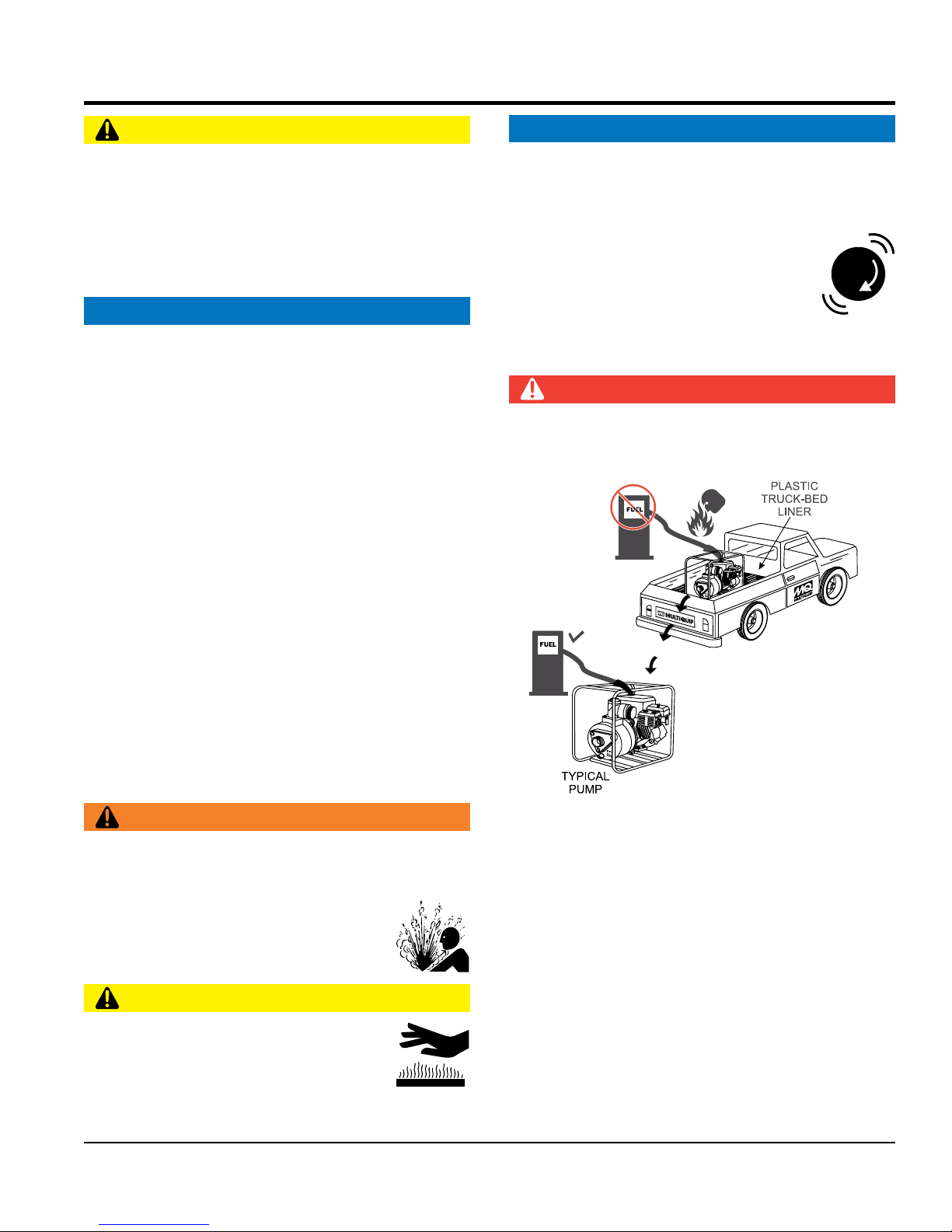
FUEL SAFETY
DANGER
DO NOT
add fuel to equipment if it is placed inside truck
bed with plastic liner. Possibility exists of explosion or
fire due to static electricity.
DO NOT
start the engine near spilled fuel or combustible
fluids. Fuel is extremely flammable and its vapors can
cause an explosion if ignited.
ALWAYS
refuel in a well-ventilated area, away from
sparks and open flames.
ALWAYS
use extreme caution when working with
flammable liquids.
DO NOT
fill the fuel tank while the engine is running
or hot.
DO NOT
overfill tank, since spilled fuel could ignite if it
comes into contact with hot engine parts or sparks from
the ignition system.
PAGE 8 — QP2TK TRASH PUMP • OPERATION AND PARTS MANUAL — REV. #1 (07/28/17)
SAFETY INFORMATION
Store fuel in appropriate containers, in well-ventilated
areas and away from sparks and flames.
NEVER use fuel as a cleaning agent.
DO NOT smoke around or near the
equipment. Fire or explosion could result
from fuel vapors or if fuel is spilled on a
hot engine.
BATTERY SAFETY (ELECTRIC START ONLY)
DANGER
DO NOT drop the battery. There is a possibility that the
battery will explode.
DO NOT expose the battery to open flames,
sparks, cigarettes, etc.The battery contains
combustible gases and liquids. If these
gases and liquids come into contact with a
flame or spark, an explosion could occur.
WARNING
ALWAYS wear safety glasses when
handling the battery to avoid eye irritation.
The battery contains acids that can cause
injury to the eyes and skin.
Use well-insulated gloves when picking up
the battery.
ALWAYS keep the battery charged. If the battery is not
charged, combustible gas will build up.
DO NOT charge battery if frozen. Battery can explode.
When frozen, warm the battery to at least 61°F (16°C).
ALWAYS recharge the battery in a well-ventilated
environment to avoid the risk of a dangerous concentration
of combustible gases.
If the battery liquid (dilute sulfuric acid)
comes into contact with clothing or skin,
rinse skin or clothing immediately with
plenty of water.
If the battery liquid (dilute sulfuric acid) comes into
contact with eyes, rinse eyes immediately with plenty
of water and contact the nearest doctor or hospital to
seek medical attention.
CAUTION
ALWAYS disconnect the
NEGATIVE battery terminal
before performing service on the equipment.
ALWAYS
keep battery cables in good working condition.
Repair or replace all worn cables.
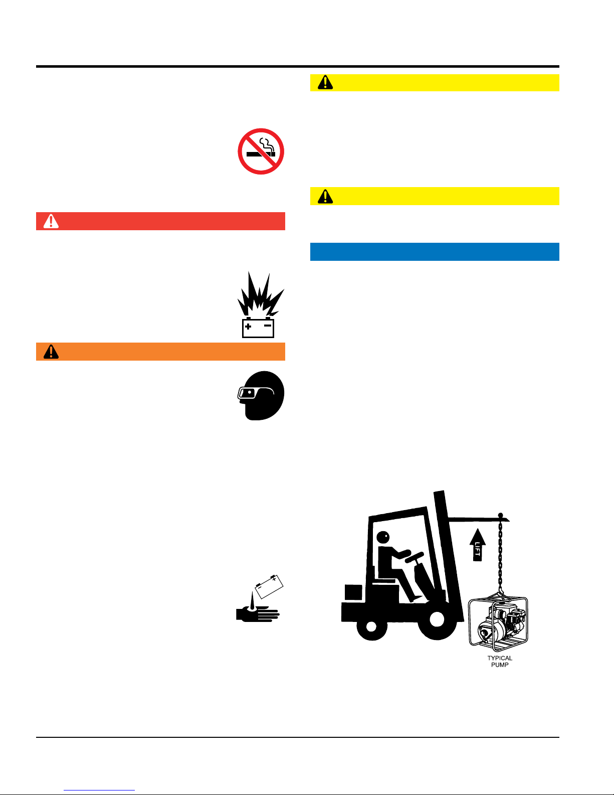
TRANSPORTING SAFETY
CAUTION
NEVER
allow any person or animal to stand underneath
the equipment while lifting.
NOTICE
Before lifting, make sure that the equipment parts (hook
and vibration insulator) are not damaged and screws are
not loose or missing.
Always make sure crane or lifting device has been
properly secured to the lifting bail (hook) of the
equipment.
ALWAYS shutdown engine before transporting.
NEVER lift the equipment while the engine is running.
Tighten fuel tank cap securely and close fuel cock to
prevent fuel from spilling.
Use adequate lifting cable (wire or rope) of sufficient
strength.
Use one point suspension hook and lift straight upwards.
DO NOT lift machine to unnecessary heights.
ALWAYS
tie down equipment during transport by
securing the equipment with rope.

QP2TK TRASH PUMP • OPERATION AND PARTS MANUAL — REV. #1 (07/28/17) — PAGE 9
ENVIRONMENTAL SAFETY/DECOMMISSIONING
NOTICE
Decommissioning is a controlled process used to safely
retire a piece of equipment that is no longer serviceable.
If the equipment poses an unacceptable and unrepairable
safety risk due to wear or damage or is no longer cost
effective to maintain (beyond life-cycle reliability) and is to
be decommissioned (demolition and dismantlement),be
sure to follow rules below.
DO NOT pour waste or oil directly onto the ground, down
a drain or into any water source.
Contact your country's Department of
Public Works or recycling agency in your
area and arrange for proper disposal of
any electrical components, waste or oil
associated with this equipment.
When the life cycle of this equipment is over, remove
battery and bring to appropriate facility for lead
reclamation. Use safety precautions when handling
batteries that contain sulfuric acid.
When the life cycle of this equipment is over, it is
recommended that the trowel frame and all other metal
parts be sent to a recycling center.
Metal recycling involves the collection of metal from
discarded products and its transformation into raw
materials to use in manufacturing a new product.
Recyclers and manufacturers alike promote the process
of recycling metal. Using a metal recycling center
promotes energy cost savings.
EMISSIONS INFORMATION
NOTICE
The diesel engine used in this equipment has been
designed to reduce harmful levels of carbon monoxide
(CO), hydrocarbons (HC) and nitrogen oxides (NOx)
contained in diesel exhaust emissions.
This engine has been certified to meet US EPA Evaporative
emissions requirements in the installed configuration.
Attempting to modify or make adjustments to the engine
emmission system by unauthorized personnel without
proper training could damage the equipment or create an
unsafe condition.
Additionally, modifying the fuel system may adversely affect
evaporative emissions, resulting in fines or other penalties.
Emission Control Label
The emission control label is an integral part of the emission
system and is strictly controlled by regulation(s).
The label must remain with the engine for its entire life.
If a replacement emission label is needed, please contact
your authorized engine distributor.
SAFETY INFORMATION
PAGE 10 — QP2TK TRASH PUMP • OPERATION AND PARTS MANUAL — REV. #1 (07/28/17)
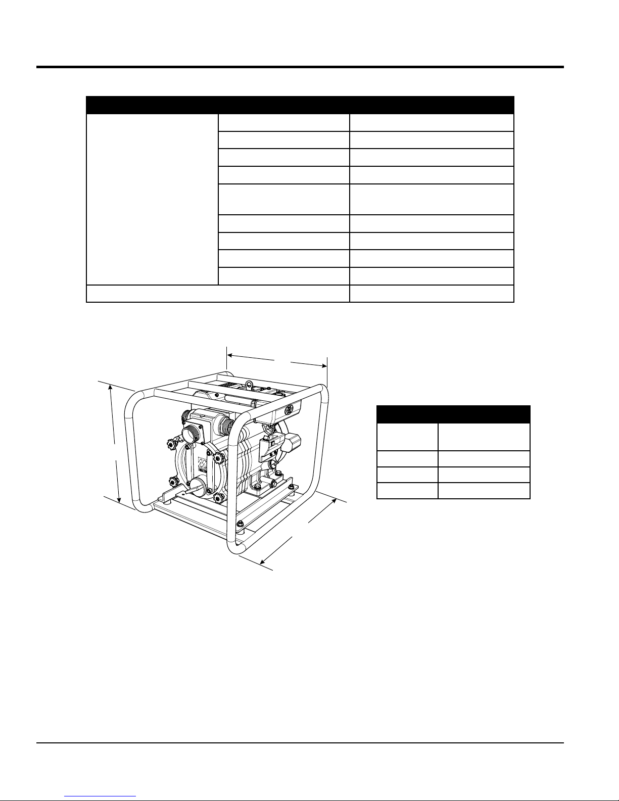
Table 1. Specifications (Pump)
Pump
Model QP2TK
Type Trash Pump
Suction 2.0 in. (50 mm.)
Discharge Size 2.0 in. (50 mm.)
Maximum Pumping
Capacity
172 gallons/minute
(650 liters/minute)
Max. Solids Diameter 1.0 in. (25.4 mm)
Max. Head 85 ft. (26.0 m)
Max. Suction Lift 25 ft. (7.62 m)
Max. Pressure 37.7 psi (260 kPa)
Dry Net Weight 157 lbs. (71 Kg.)
SPECIFICATIONS (PUMP)
C
B
A
Figure 1. Dimensions
Table 2. Dimensions
Reference
Letter Dimension in. (mm)
A 23.8 (605)
B 23.4 (595)
C 26.9 (685)
QP2TK TRASH PUMP • OPERATION AND PARTS MANUAL — REV. #1 (07/28/17) — PAGE 11
SPECIFICATIONS (ENGINE)
Table 3. Specifications (Engine)
Model KUBOTA OC60-E4
Type Oil-Cooled and Forced Air-Cooling
Diesel Engine
Displacement 16.8 in3(0.276 liters)
Horsepower 6.0 HP (4.5 kW) @ 3,600 RPM
Idle Speed 1,300 R.P.M.
Fuel Type Diesel Fuel
Fuel Capacity .95 (US) Gal. (3.6 Liters)
Fuel Consumption .41 (US) Gal./Hr. (1.55 Liters/Hr.)
Fuel Type No. 2 Diesel Fuel, ATSM D975
Lube Oil Capacity 1.37 quarts (1.3 liters)
Engine Oil Type API Service CF-class (SEA #30, 20, 10W30)
Starting Method Electric Start
Air Cleaner Type Dry Element
Battery Type 12V, 27AH
Battery Tray Dimensions (L x W x H) 10.1 x 7.0 x 1.2 in. (256.5 x 178 x 30.5 mm)
Weight 83.7 lbs (38 Kg.)
0
10
20
30
40
50
60
70
80
90
0 50 100 150 200
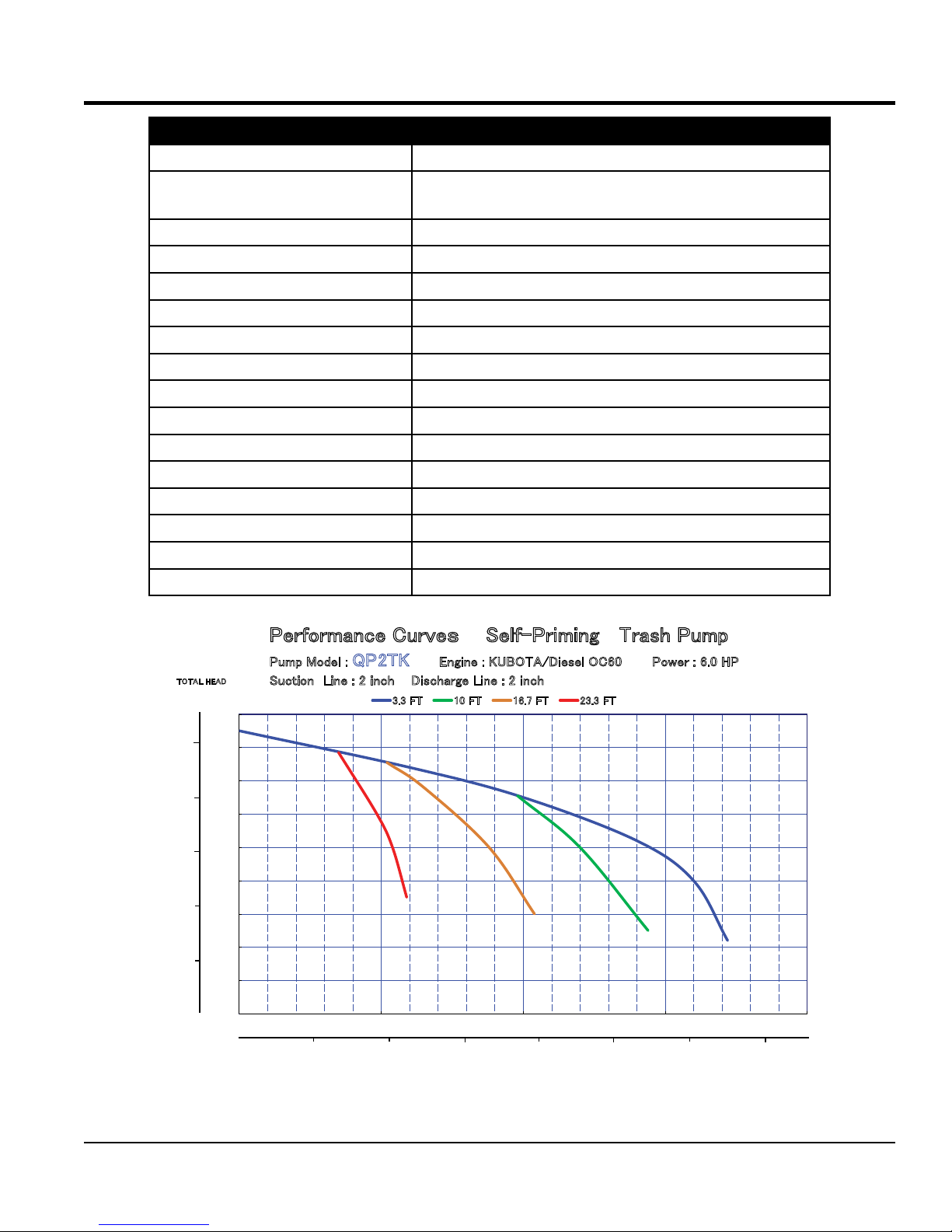
Performance CurvesSelf-Priming Trash Pump
Pump Model : QP2TK Engine : KUBOTA/Diesel OC60 Power : 6.0 HP
Suction Line : 2 inch Discharge Line : 2 inch
3.3 FT 10 FT 16.7 FT 23.3 FT
3.3 FT
10 FT
16.7 FT
23.3 FT
U.S GALLONS
PER MINUTE
LITTERS
PER MINUTE
400 600100 300 500 700
0
TOTAL HEAD
METERS FT
5
10
15
20
25
Figure 2. QP2TK Performance Curve

PAGE 12 — QP2TK TRASH PUMP • OPERATION AND PARTS MANUAL — REV. #1 (07/28/17)
ELEVATION
Higher elevations will effect the performance of the pump.
Due to less atmospheric pressure at higher altitudes,
pumps DO NOT have the priming ability that they have at
sea level. This is due to the “thinner air” or lack of oxygen
at higher altitudes.
A general rule of thumb is that for every 1,000 feet of
elevation above sea level a pump will lose one foot of
priming ability.
For example, in Flagstaff, Arizona where the elevation is
approximately 7,000 feet, the pump would have a suction
lift of only 18 feet rather than the 25 feet at sea level.
Table 4 shows suction lift at various elevations.
Table 4. Suction Lift at Various Elevations
Altitude
Feet
(Meters)
Suction Lift in Feet (Meters)
Sea Level 10.0 (3.048) 15.0 (4.572) 20.0 (6.096) 25.0 (7.620)
2,000 (610) 8.80 (2.680) 13.2 (4.023) 17.6 (5.364) 22.0 (6.705)
4,000 (1,219) 7.80 (2.377) 11.7 (3.566) 15.6 (4.754) 19.5 (5.943)
6,000 (1,829) 6.90 (2.103) 10.4 (3.169) 13.8 (4.206) 17.3 (5.273)
8,000 (2,438) 6.20 (1.889) 9.30 (2.834) 12.4 (3.779) 15.5 (4.724)
10,000 (3,048) 5.70 (1.737) 8.60 (2.621) 11.4 (3.474) 14.3 (4.358)
Table 5 shows percentage drops in performance as
elevation increases.
Table 5. Performance Loss at Various Elevations
Altitude
Feet (Meters) Discharge Flow Discharge Head
Sea Level 100% 100%
2,000 (610) 97% 95%
4,000 (1,219) 95% 91%
6,000 (1,829) 93% 87%
8,000 (2,438) 91% 83%
10,000 (3,048) 88% 78%
GENERAL INFORMATION
APPLICATION
The QP2TK Trash Pump is designed for dewatering
applications. Both the suction and discharge ports on the
this trash pump use a 2-inch diameter opening, which
allows the pump to pump at a rate of approximately 172
gallons/minute (gpm) or 650 liters/minute (lpm).
This Wet Primed pump requires that the pump casing
is first filled with water to assist with initial self-priming
operations. Once a partial vacuum is created within the
unit, the reduced atmospheric pressure allows water to
flow through the suction line and the centrifugal force of
the impeller/volute assembly permits water to be expelled
from the discharge ports.
ENGINE
This trash pump is powered by a 6.0 HP, oil and air-cooled
KUBOTA diesel engine.
TRASH PUMP
Trash pumps derive their name from their ability to handle
a greater amount of debris and solids than standard
centrifugal pumps. This pump generally handles solids up
to 1/2 the size of the discharge opening making them less
likely to clog. Also trash pumps are capable of handling
water with 25% solids by weight.
The advantage of using a trash pump is that it can be quickly
and easily disassembled in the field “without tools” and
easily cleaned when clogged.
SUCTION LIFT
This pump is intended to be used for dewatering applications
and is capable of suction lifts up to 25 feet at sea level. For
optimal suction lift performance, keep the suction hose or
line as short as possible. In general, always place the pump
as close to the water as possible.
PUMP SUPPORT
The pump should always be placed on solid stationary
ground in a level position.
NEVER place the pump on soft soil. The suction hose or
pipe connection should always be checked for tightness
and leaks. A small suction leak in the hose or fittings could
prevent the pump from priming.

QP2TK TRASH PUMP • OPERATION AND PARTS MANUAL — REV. #1 (07/28/17) — PAGE 13
NOTES
PAGE 14 — QP2TK TRASH PUMP • OPERATION AND PARTS MANUAL — REV. #1 (07/28/17)
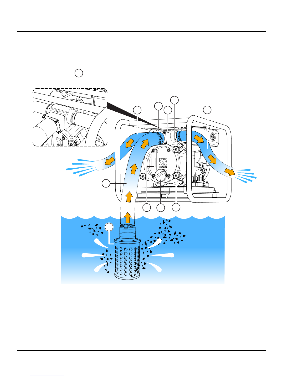
PUMP COMPONENTS
14
6
78
9
3
2
5
4
10
Figure 3 shows key component areas of the QP2TK.
Figure 3. QP2TK Key Component Callouts

QP2TK TRASH PUMP • OPERATION AND PARTS MANUAL — REV. #1 (07/28/17) — PAGE 15
1. Pump — The model QP2TK is a 2-inch trash pump
used in general dewatering applications. Typical
dewatering applications consist of: manholes, septic
tanks, ponds, ditch water, silt water, muddy water, and
water with debris.
2. Fill Cap — Prior to operations, the pump casing MUST
be filled with water. Remove this cap to add water to
the pump. After the initial prime, a sufficient amount of
water will be retained in the casing so that the operator
will not need to re-prime later.
If the casing is dry or has insufficient water, the pump
will have difficulty in priming which could lead to
premature mechanical seal wear thus causing damage
to the pump.
3. Discharge Port — The pump is equipped with left and
right side discharge ports. These ports are 2” male
NPT thread and can accommodate discharge hose or
pipe. Quick disconnect (Cam and Groove lock) hoses
can be fitted onto the discharge ports with an optional
coupler (A200A).
4. Discharge Hose — This pump is fitted with 2” male
NPT thread discharge ports and can accommodate
either threaded discharge hose or pipe. Quick
disconnect (Cam and Groove lock) hoses can be
fitted onto the discharge ports with an optional coupler
(A200A). Make sure hoses lays flat and are not kinked.
Contact MQ Sales Department for ordering information.
5. Suction Port — This pump is fitted with a 2” male NPT
thread suction port and can accommodate either a
threaded or quick disconnect (Cam and Groove lock)
hose. For quick disconnect connections, an optional
coupler (A200A) is necessary. Contact MQ Parts
Department for ordering assistance.
PUMP COMPONENTS
6. Suction Hose — Use only recommended suction
hoses. This pump is fitted with a 2” male NPT thread
suction port and can accommodate threaded or quick
disconnect (Cam and Groove lock) suction hose. Cam
and Groove lock hose can be fitted onto the suction
port with an optional coupler (A200A). Make sure
the suction hose is not kinked. Contact MQ Sales
Department for ordering information
7. Clean-Out Cover — When the pump is subjected to
applications where large quantity of debris is present,
it may be necessary to clean out the casing cavity of
large rocks and such that have not passed through
the pump.
8. Drain Plug — After usage, and for storage, remove this
plug and drain all water from the pump casing
9. Strainer — Always attach a strainer to bottom side of
the suction hose to prevent large objects and debris
from entering the pump. Strainer should be positioned
so that it will remain completely under water. Running
the pump with the strainer above water for long periods
can damage pump.
10. Locking Knobs — To open and gain access to the
pump’s clean-out cavity, loosen the four locking
knobs. Turn counter-clockwise to loosen. Grip the
cover handles and twist counter-clockwise. Once the
cover is clear of the four knob fasteners, pull the cover
out towards you.
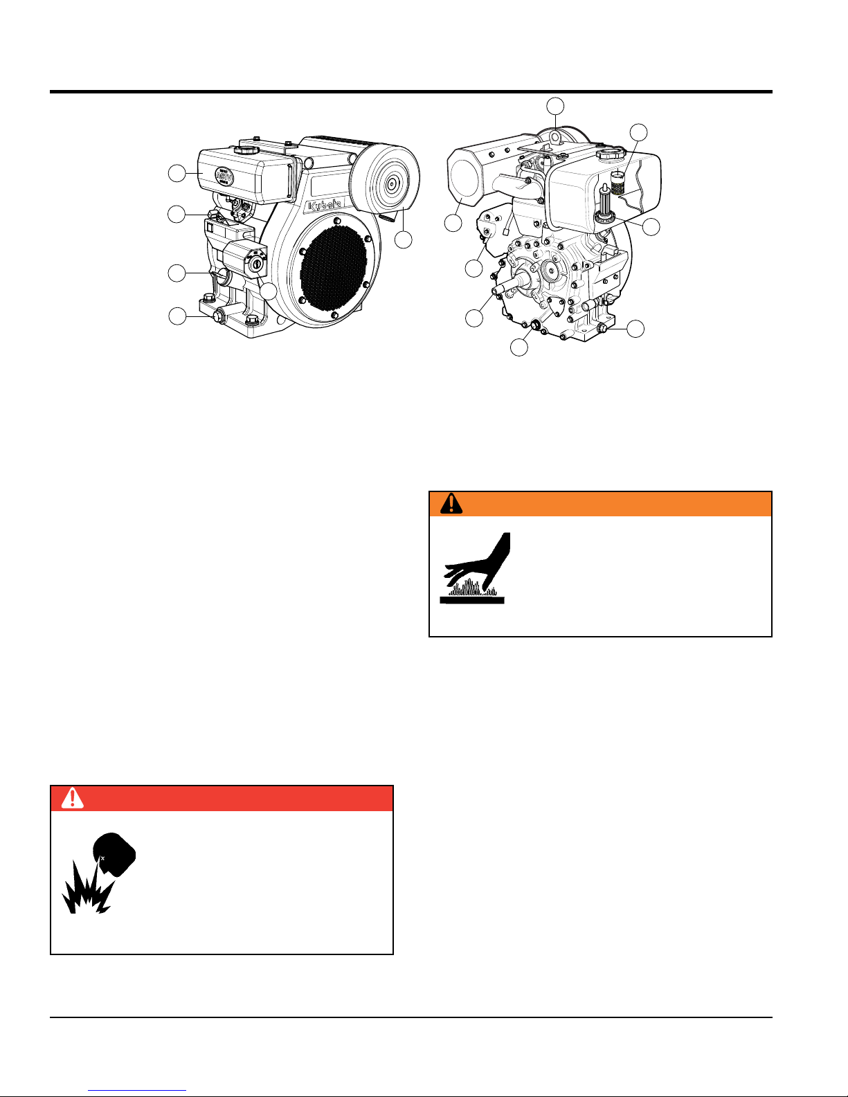
PAGE 16 — QP2TK TRASH PUMP • OPERATION AND PARTS MANUAL — REV. #1 (07/28/17)
6. Air Cleaner/Cover — Prevents dirt and other debris
from entering the fuel system. Remove wing-nut on
top of air filter cover to gain access to filter element.
7. Muffler — Used to reduce noise and emissions.
8. Engine Lifting Hook — Attach a suitable strap or
chain to this hook when lifting of the engine is required
9. Fuel Strainer — Prevents dirt and debris from entering
the fuel injection system.
10. Fuel Filter — Prevents dirt and debris from entering
the fuel injection system.
11. Oil Filter — Remove this bolt to gain access
(internal) to the engine oil filter. Service the oil filter
as recommended in the maintenance section of this
manual.
12. Crankshaft — Connect this shaft to the pump engine
coupling.
13. Electric Starter — Starts engine when ignition key is
rotated to the "START" position.
WARNING
Engine components can generate
extreme heat. To prevent burns,
DO NOT touch these areas while the
engine is running or immediately after
operating. NEVER operate the engine
with the muffler removed.
Figure 4. Engine Controls and Components
3
2
1
5
7
6
4
13
1
12
8
11
10
9
INITIAL SERVICING
The engine (Figure 4) must be checked for proper lubrication
and filled with fuel prior to operation. Refer to the manufac-
turer’s Engine manual for operating and servicing information.
1. Oil Drain Plugs —There are two oil drain plugs, one
on each side of the engine. Remove either plug to drain
engine oil from the engine crankcase.
2. Dipstick — Remove dipstick to determine if the engine
oil level is low. If low, add oil as specified.
3. Engine Speed Control Lever — This lever is
connected to the throttle control which is located on
the side of the engine. Use this lever to control engine
speed.
4. Fuel Filler Cap/Fuel Tank — Remove this cap to add
diesel fuel to the tank. After refueling, always make
sure the fuel cap is properly tighten. DO NOT over
fill. For additional information refer to engine owner’s
manual.
.
5. Ignition Switch — With ignition key inserted, turn key
clockwise to start engine.
DANGER
Adding fuel to the tank should be done
only when the engine is stopped and has
had an opportunity to cool down. In the
event of a fuel spill, DO NOT attempt to
start the engine until the fuel residue has
been completely wiped up, and the area
surrounding the engine is dry.
BASIC ENGINE

QP2TK TRASH PUMP • OPERATION AND PARTS MANUAL — REV. #1 (07/28/17) — PAGE 17
INSPECTION (ENGINE)
CAUTION
DO NOT attempt to operate the pump
until the Safety Information, General
Information and Inspection sections
of this manual have been read and
thoroughly understood.
Engine Oil Check
1. To check the engine oil level, place the pump on secure
level ground with the engine stopped.
2. Remove the filler dipstick from the engine oil filler hole
(See Figure 5) and wipe clean.
Figure 5. Engine Oil Dipstick (Removal
3. Insert and remove the dipstick without screwing it into
the filler neck. Check the oil level shown on the dipstick.
4. If the oil level is low (See Figure 6), fill to the edge
of the oil filler hole with the recommended oil type
(Table 3 and Table 6). Maximum oil capacity is 1.37
quarts(1.3 liters).
Figure 6. Engine Oil DipStick (Oil Level)
DIPSTICK
UPPER LIMIT
LOWER LIMIT
CAUTION
You must frequently check the oil level
of the engine.There is no low oil shutoff
feature for protection and operating the
pump with low oil levels will cause severe
damage to the engine.
Fuel Check
1. Remove the fuel cap (Figure 7) located on top of fuel
tank.
Figure 7. Fuel Check
2. Visually inspect the fuel level. The recommended fuel
to use is diesel fuel No. 2-D (ASTM D975).
3. When refueling, DO NOT top-off the tank, and wipe up
any spilled fuel immediately!
Table 6. Oil Type
Season Temperature Oil Type
Summer 25°C or Higher SAE 10W-30
Spring/Fall 25°C~10°C SAE 10W-30/20
Winter 0°C or Lower SAE 10W-10
DANGER
Motor fuels are highly flammable and can
be dangerous if mishandled. DO NOT
smoke while refueling. DO NOT attempt
to refuel the pump if the engine is hot!
or running.
FUEL
TANK
FUEL
CAP

PAGE 18 — QP2TK TRASH PUMP • OPERATION AND PARTS MANUAL — REV. #1 (07/28/17)
7. The discharge side may utilize proper discharge hoses,
PVC pipe, or concrete pipe.
8. Check that discharge hoses lay flat and as straight as
possible. Remove any sharp bends or kinks from the
hose so the water flow cannot be blocked.
9. Once the engine is started; and depending on the
application set-up, the priming process will take a few
moments before water begins to flow.
10. The performance of the pump (Flow, Head, Water
Velocity, and Pressure) is dependent on the many
factors that surround the application. These factors
include, but are not limited to: operating altitude, suction
lift, discharge and suction hose diameter and length,
overall friction loss coefficients, the specific gravity of
the fluid to be pumped, the fluid temperature, and total
discharge head.
CAUTION
The strainer should be positioned so it will remain
completely under water. Running the pump with the
strainer above water for long periods can damage the
pump.
1. It is advantageous to place the pump as close as
possible to the water source (Figure 8) on a solid, level
operating surface.The most critical factor for successful
pump operations is not to exceed 25 feet (7.62 meters)
total suction lift (at sea level).
2. Ensure that the pump has the proper level of engine oil.
3. Initially prime the pump by removing the fill cap
(see Figure 3) and filling the casing with water. If the
pump casing is not filled with water prior to operations,
it will not be able to start the pumping process and you
risk overheating the mechanical seal assembly.
4. Attach the proper suction and discharge hoses to the
pump ports.Ensure that the hoses O-rings are in place,
and that hoses do not show any cracks, gouges, or
holes. The hoses should not be kinked, and must be
secured tightly to their respective ports.
5. A proper suction hose is commonly reinforced with rigid
PVC helix and is specifically designed to safeguard
against collapsing during pumping operations. It is
essential that the pump utilize a suction hose with the
same diameter as the suction port.
6. Ensure that the strainer is placed on the end of the
suction hose, and that the hose is placed in the water
source in such a manner as not to bury the strainer
into the sand or silt.
SETUP
Figure 8. Pump Placement

QP2TK TRASH PUMP • OPERATION AND PARTS MANUAL — REV. #1 (07/28/17) — PAGE 19
OPERATION
BEFORE STARTING
1. Clean the unit, removing dirt and dust, particularly the
engine cooling air inlet, and air filter.
2. Check the air filter for dirt and dust. If air filter is dirty,
replace air filter with a new one as required.
3. Check fastening nuts and bolts for tightness.
4. The QP2TK utilizes a battery for electric start
operations. Check the security, connections, and
integrity of the battery.The battery tray measures 10” x
7” x 12” and will accept any quality 12V “C” post 12N24-
3A type battery (ex. Interstate,YUASA, and Champion).
CAUTION
DO NOT attempt to operate the pump until the Safety,
General Information and Inspection sections of this
manual have been read and thoroughly understood.
CAUTION
DO NOT pump flammable fluids, corrosive chemicals or
fluids containing toxic substances. These fluids can create
potentially dangerous health and environmental hazards.
Contact local authorities for assistance.
CAUTION
This pump uses a water-cooled mechanical seal to
prevent water from seeping into the engine.The passage
of water through the pump casing lubricates the seal and
prevents it from overheating. NEVER operate the pump
without water in the casing as this will cause damage to
the mechanical seal.
STARTING THE ENGINE
1. Move the engine speed control lever to the START
position (Figure 9).
Figure 9. Engine Speed Lever (START Position)
2. Place the ignition key in the start position (Figure 10).
Release key when engine starts.
Figure 10. Ignition Switch (Start Position)
START
STOP
SPEED CONTROL
LEVER
ST
ART
PAGE 20 — QP2TK TRASH PUMP • OPERATION AND PARTS MANUAL — REV. #1 (07/28/17)
3. Before the pump is placed into full operations, run the
engine (at low RPM) for several minutes and check for
any abnormal conditions such as extreme vibrations,
loose components, and fluid leaks.
4. Begin pumping.
STOPPING THE ENGINE
Normal Shutdown
1. Place the engine speed control lever in the low speed
position and run the engine for about three minutes
with no load.
2. Place the ignition switch key in the OFF position.
3. Place the engine speed control lever in the STOP position.
4. Remove all hoses from the pump.
CAUTION
ALWAYS run engine at full speed while pumping.
CAUTION
When stopping the engine, reduce the load slowly. DO NOT
stop engine suddenly since it may cause the temperature
to rise abnormally.
OPERATION
Emergency Shutdown
1. To stop engine immediately, quickly place the ignition key
in the OFF position.
This manual suits for next models
1
Table of contents
Popular Water Pump manuals by other brands

rodac
rodac RQAB21 User's Manual and Exploded View

Harbor Freight Tools
Harbor Freight Tools Pacific Hydrostar 68422 Owner's manual & safety instructions

Hirschmann
Hirschmann Rotarus 50 Series Short instruction manual

Wilo
Wilo Drain MTC 32 Installation and operating instructions

Limora
Limora Mitsuba FITTING INSTRUCTION

belardi
belardi 4B Series Use and maintenance instructions

KSB
KSB EtaLine Pro Series Installation and operating manual

Graco
Graco Fire-Ball 300 instruction manual

Dustcontrol
Dustcontrol TPR 40 Original instructions

SprayTECH
SprayTECH EPX2255 owner's manual

Grindex
Grindex 8109.282 Salvador Installation, operation and maintenance manual

Giant
Giant GP5128 Operating instructions manual


