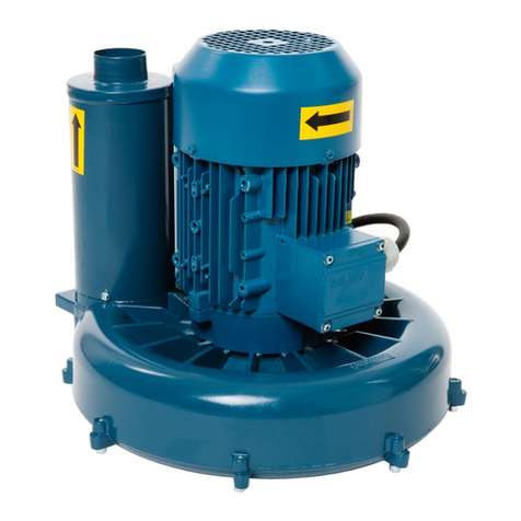
Dustcontrol TPR 40 User manual

TPR 47 22 kW
Bruksanvisning i original
Original instructions
Originalbetriebsanleitung
Oorspronkelijke gebruiksaanwijzing
Alkuperäiset Ohjeet
Original brugsanvisning
VARNING! Läs bruksanvisningen före användning av maskinen.
WARNING! Read the instruction manual before using the machine.
ACHTUNG! Bitte lesen Sie die Betriebsanleitung vor Inbetriebnahme der Maschine
sorgfältig durch.
WAARSCHUWING! Lees de gebruiksaanwijzing voor het gebruik van de
machine.
VAROITUS! Lue käyttöohjeet ennen laitteen käyttöä.
ADVARSEL! Læs manualen, før du bruger maskinen.
Part No 9048-A

TPR 47, 22 kW - 2 Part No 9048-A
Dustcontrol reserves the right to change specifications without notice and is under no obligation to alter
previously delivered products. Dustcontrol is not responsible for errors or omissions in this catalogue.
Dustcontrol reserverar sig för tryckfel och produktförändringar.
Keine Gewähr für Druckfehler. Produktänderungen vorbehalten.
Tillverkare/Manufactured by/Hersteller/Fabrikant/
Valmistaja/Producenter:
Dustcontrol AB
Box 3088, Kumla Gårdsväg 14
SE-145 03 Norsborg
Tel: + 46 8 531 940 00
Fax: + 46 8 531 703 05
support@dustcontrol.se
www.dustcontrol.com
Såld av/Sold by/Verkauft von/Verkocht door/
Myyjä/Sælges af:
Dustcontrol is niet aansprakelijk voor drukfouten in deze gebruikers handleiding of voor tussentijdse wij-
zigingen. Dustcontrol behoudt zich het recht voor de specificaties van haar machines te wijzigen zonder
voorafgaande aankondiging en is niet verplicht reeds geleverde machines hierop aan te passen. Uitvo-
ering en leveringsomvang kunnen plaatselijk afwijken.
Dustcontrol ei vastaa mahdollisista painovirheistä eikä tuotemuutoksista.
Dustcontrol forbeholder sig ret til at ændre specifikationerne uden forudgående varsel og er ikke forpligtet
til ændring af tidligere leverede produkter. Dustcontrol er ikke ansvarlig for trykfejl mv. i denne manual.

TPR 47, 22 kW - 3 Part No 9048-A2017-05-24
Innehållsförteckning
Säkerhetsföreskrifter _________ 5
Tekniska data_____________ 5-6
Funktionsbeskrivning _________ 6
Mått och uppställning_________ 7
Installation ________________7-9
Provkörning _______________ 10
Underhåll _______________ 11-12
Tillbehör__________________ 13
Garanti___________________ 13
Felsökning ________________ 14
Reservdelar ____________ 65-67
Vakuumventil ___________ 68-69
EG-försäkran ____________70-71
Dustcontrol Worldwide_______ 72
Contents
Safety Considerations _______ 15
Technical Data___________15-16
System Description _________ 17
Dimensions and Arrangements 17
Installation ______________18-19
Test Running ______________ 20
Service ________________21-22
Accessories _______________ 23
Warranty _________________ 23
Trouble Shooting ___________ 24
Spare Parts ____________ 65-67
Vacuum relief valve ______ 68-69
EC-declaration___________70-71
Dustcontrol Worldwide_______ 72
Inhaltsverzeichnis
Sicherheitsvorschriften ______ 25
Technische Daten __________ 26
Funktionsbeschreibung ______ 27
Maße und Aufstellung _______ 27
Installation ______________28-29
Probelauf _________________ 30
Wartung ________________31-32
Zubehör __________________ 33
Garantie__________________ 33
Fehlersuche_______________ 34
Ersatzteile _____________ 65-67
Onderdrukklep __________ 68-69
EG-Konformitätserklärung __70-71
Dustcontrol Worldwide_______ 72
SVENSKAENGLISHDEUTSCH
Inhoud
Veiligheidsvoorschriften ______ 35
Technische gegevens _______ 36
Systeem beschrijving________ 37
Afmetingen _______________ 37
Installatie ______________ 38-39
Testen ___________________ 40
Service ________________41-42
Accessoires _______________ 43
Garantie__________________ 43
Probleemoplossingen _______ 44
Onderdelen ____________ 65-67
Vacuum relief valve ______ 68-69
EG-verklaring____________70-71
Dustcontrol Wereldwijd ______ 72
NEDERLANDS
Turvamääräykset ___________ 45
Tekniset tiedot __________ 45-46
Toimintakuvaus ____________ 46
Mitat ja asennus____________ 47
Asennus________________47-49
Koekäyttö_________________ 50
Huolto _________________51-52
Sisällysluettelo
SUOMI
Lisävarusteet ______________ 53
Takuu____________________ 53
Vianetsintä________________ 54
Varaosat ______________ 65-67
Alipaineventtiili __________ 68-69
EY-ilmoitus______________70-71
Dustcontrol Worldwide_______ 72

TPR 47, 22 kW - 4 Part No 9048-A
DANSK
Indholdsfortegnelse
Sikkerhedsregler _______________ 55
Tekniske data__________________ 56
Funktionsbeskrivelse ____________ 57
Dimensioner og opstilling_________ 57
Installation _________________ 58-59
Afprøvning ____________________ 60
Vedligeholdelse ______________61-62
Tilbehør ______________________ 63
Garanti_______________________ 63
Fejlfinding ____________________ 64
Reservedele _______________ 65-67
Vakuumventil _______________ 68-69
EG-erklæring ________________70-71
Dustcontrol Worldwide___________ 72

TPR 47, 22 kW - 15 Part No 9048-A2017-05-24
Safety Considerations
Read all instructions before the machine/installation
is commissioning.
The equipment must be installed and maintained pro-
perly by qualified personnel who have study this user
instruction. Dustcontrol does not take responsibility
for defective installation or maintenance.
Warning! When using electric machines, basic sa-
fety precautions should always be followed to reduce
the risk of fire, electric shock and personal injury,
including the following:
1. Work area environment
Keep the area around the central unit clean.
Do not store or work with flammable liquids or
gases near the machine.
2. Overload
If there is an alarm signal it should be care-
fully checked out to see that the machine is
undamaged. If there are any damaged parts
these should be repaired by a Dustcontrol
authorized service
centre. Always follow the regulations pertinent
to the material you are working with. Do not
use the machine for purposes that it is not
intended for.
3. Bodily injuries
Warning - High negative pressure
Do not start the pump without having it con-
nected to the duct work. Do not adjust the
vacuum relief valve while the pump is ope-
rating. Never let the suction come in contact
with parts of the body, for example a hand.
The pump generates a high negative pressure,
severe injury may result.
Warning - Very hot exhaust air
Exhaust air can be very hot, up to 150OC.
4. Electricity
A separate lockable disconnect must be instal-
led where it is readily accessible to the pump.
Do not repair the electric components yourself,
get somebody qualified. Faults may cause
injury. The electrical connections may only be
performed by a certified electrician. See also
under section 7, ’Warning’.
5. Important measure
The electrical disconnect should be locked in
the ”off” position before demounting the safety
panels or ducting.
6. Checking for damage
Check the machine regularly for damage. If
there are any damaged parts these should be
repaired by a Dustcontrol authorized service
centre.
7. Warning
Use only accessories and replaceable parts
which are available in Dustcontrol catalogue.
When using non-genuine parts, especially
filters and plastic sacks, dust leaks could occur
which may be hazardous to health.
Description TPR 35 TPR 40 TPR 43 TSR 43 TPR 47 TSR 47 TPR 50 TSR 50
Motor kW 11 15 18,5 18,5 22 22 30 30
Pump RPM rpm 3500 4000 4300 4300 4700 4700 5000 5000
Weight kg 400 400 430 430 450 450 530 530
Max dP kPa 22 26 28 46 29 50 30 54
Nom. Pressure
kPa 20 22 22 35 23 37 25 40
Max Q m3/h 1000 1200 1400 650 1500 700 1600 800
Sound Level of
Unit 1m dB(A) 66 66 66 66 66 66 66 66
Inlet/Outlet Ømm 160/160 160/160 160/160 108/108 160/160 108/108 160/160 108/108
Technical Data
ENGLISH

TPR 47, 22 kW - 16 Part No 9048-A
Technical Data
CAPACITY AND POWER CONSUMPTION
kPa Pu
60
50
40
30
20
10
0
10
20
30
kW P
200 400 600 800 1000 1200 1400 1600
7
6
4
8
1
7
5
3
2
1
6
8
425
3
Q
m3/h
1. TPR 35 11 kW
2. TPR 40 15 kW
3. TPR 43 18,5 kW
4. TSR 43 18,5 kW
5. TPR 47 22 kW
6. TSR 47 22 kW
7. TPR 50 30 kW
8. TSR 50 30 kW
POWER RATING
Hz TPR 35 TPR 40 TPR 43 TSR 43 TPR 47 TSR 47 TPR 50 TSR 50
11 kW 15 kW 18.5 kW 18.5 kW 22 kW 22 kW 30 kW 30 kW
220-240/
380-420 50 - 106802 107202 107252 107702 107752 109202 109252
380-420/
660 50 106600 106800 107200 107250 107700 107750 109200 109250
500 50 - 106801 107201 107251 107701 107751 109201 109251
575 60 - 106806 107206 107256 107706 107756 109206 109256
220/440 60 - 106804 107204 107254 107704 107754 109204 109254
V
Part No.
e capacity curves for Dustcontrol vacuum producers have
been measured and are stated empirically. Outlet pressure losses
from a normal outlet (silencer, back-ow valve/bend) have been
accounted for in the curve. Additional equipment such as a dif-
fuser can result in increased pressure loss and must be taken into
consideration.
Stated air-ows are for standard air (101.3 kPa@ 20oC).
e stated curves are for negative application, all pressures stated
are assumed to be below relative atmospheric pressure at sea
level. ese devices can also be used for positive pressure applica-
tion and will generate a greater pressure dierential.

TPR 47, 22 kW - 17 Part No 9048-A2017-05-24
ENGLISH
System Description
Regenerative blowers
Dustcontrol’s turbopumps are regenerative blo-
wers. TPR has two impellers that are connected
for parallel flow. The impellers rotate in the blower
housing through extremely low tolerances. The
pump cannot tolerate contaminated airflow. TPR
compresses air and it is therefore natural that it
becomes hot while running.
Cooling air
Turbopumps with TPR designation are parallel
connected two stage belt driven units. Cooling air
is bled into the pump through a vacuum relief valve
which is adjustable. The vacuum pressure in the
system is thereby maintained at a constant level
even if the airflow changes.
The motor and vacuum relief valve receive cooling
air from the bottom of the unit housing. The free
passage of cooling air must be ensured. As stan-
dard screen skirts are delivered with the pump as
an protecting against leaves, papers etc.
Back flow valve
The pump is delivered standard with a back flow
relief valve. In multiple pump installations air will
not flow back through a non-operating pump.
Belt drive
The pump is belt driven. Drive ratio and motor size
determine the capacity of the pump.
If changes are to be made to performance charac-
teristic of the pump, this can be done by changing
the motor and drive ratio. Contact Dustcontrol
and you will recieve more information. Please see
addresses and phone numbers on the last page of
this document.
Thermal overload protection
For protection on the pump bearings the pump has
thermal protection which will shut down the pump
at 120OC. The thermal protection has to be con-
nected to the control panel.
Dimensions and Arrangements
TPR 35, TPR 40, TPR 43, TPR 47, TPR 50

TPR 47, 22 kW - 18 Part No 9048-A
Installation
A. Allowed pressures during installation.
B. Do not lift from this side.
C. The pump should be installed on a concrete pad. A second pump may be moun-
ted on the top of the first pump.

TPR 47, 22 kW - 19 Part No 9048-A2017-05-24
1. Ancor the pump to the concrete pad.
2. Remove the pump covers and assemble the
protection screen skirt if this is required (A).
3. Connect the ducting to both the inlet and the
outlet. Do not start the pump without having it
connected to the ductwork.
4. The pump inlet should always be connected to a
separator with a filter unit (B). The pump cannot
tolerate contaminated airflow .
5. Extra silencing can be installed if the outlet
sound level is to be lowered from
approximately 75 dB(A) to approximately 62-64
dB(A). See Accessories on page 24.
6. If the outlet is vertical, and exposed to the ele-
ments, rain protection should be installed (C).
Exhaust air can be very hot, up to 150 OC.
7. Electrical connections may only be performed
by a certified electrician. A separate lockable
disconnect should be installed where it is readily
accessible and within view of the pump.
8. Thermal overload protection must be installed to
validate the warranty.
9. The control panel must be equipped with an
overload protection that should be adjusted and
tested by a certified electrician. Check for cor-
rect motor rotation.
ENGLISH

TPR 47, 22 kW - 20 Part No 9048-A
Test Running
1. Verify that the power is locked out. Inspect the
belt tension (Figure B next page), rotate the
pump and listen for any sound indicating worn
bearings or misaligned impellers. Check that
the inlet and outlet are properly connected.
Also check that the vacuum relief valve is con-
nected.
2. Mount the covering panels. Check that no per-
sons can be hurt if the pump starts and that all
outlets are closed.
3. Connect a manometer for negative pressure
calibrated to min. -50 kPa to the suction side
as close to the pump as possible.
4. Power up the pump and listen carefully for the
following sounds; A high pitch whine is nor-
mal sound from the impeller blades. As pump
draws cooling air from the vacuum relief valve
a weak hissing should be heard.
5. Measure the pressure. Compare with the di-
mension point. The pressure can be adjusted
by adjustment of the vacuum relief valve. See
- Adjusting the vacuum relief valve.
6. Check the function and tightness of the con-
nected exhaust system.
7. Open the number of outlets the system is di-
mensioned for. The vacuum relief valve should
now be totally closed.
8. It is normal that the pump becomes hot during
operation.

TPR 47, 22 kW - 21 Part No 9048-A2017-05-24
Service
The pump should be inspected at least twice a year and
lubricated according to the lubrication intervals at the
bottom of this page.
1. Start the pump and listen for abnormal sounds.
When all outlets are closed a weak hissing sound
should be heard from the vacuum relief valve.
2. Shut off the pump and lock out the electrical service.
3. Remove the protective panels from the pump.
4. Rotate the pump manually and listen for any sounds
indicating a worn bearing or misligned impellers.
5. Check the condition and tension of the drive belts.
The drive belts are matched, therefore new and old
belts should never be used together. Always change
the whole set. (A).
Changing the belts
- Lift the motor mounting plate with nut (1).
- Change belts.
- Tighten the belts with nut (2) and adjust to the ten-
sion illustrated (B).
6. Check that the axles, pump and motor are parallel
and the pulleys are true. The belts should not run on
an angle into the pulleys. The inclination of the pump
can be changed with screw (3), fig C.
7. The bearings of the turbopump should be lubricated
with Dustcontrol bearing grease for turbopumps,
Part No. 9928.
Lubrication
- The front bearing should be lubricated using the
grease nipple (4), fig (C). Press grease in until it
comes out along the axle.
- The back bearing should be lubricated by removing
the finned bearing cover plate (5) and checking the
condition of the grease. Fill the cavity 2/3 full with
new grease.
- Exchange the O-ring, Part No. 4789 and replace the
bearing cover plate.
Lubrication Interval
p TPR 47
22 kPa 1500 h
25 kPa 1500 h
28 kPa 1000 h
30 kPa -
40 kPa -
ENGLISH

TPR 47, 22 kW - 22 Part No 9048-A
8. Disassemble the vacuum relief valve (D).
Clean and lubricate shaft and bearings. Check
the rubber gasket (E). Change if cracked or
harden (Part No. 4710).
Check the function of the hydraulic
damper (F).
D
F
1.
4.
2.
3.
E
Adjusting the vacuum relief valve
The valve is pre-adjusted with a negative pressure (18
kPa). If this is to be adjusted the following proce-
dure is used:
- Connect a manometer to the suction side and mea-
sure with fully closed inlet.
- Shut down the pump and demount the vacuum
relief valve.
- Remove the damper cover (1) and measure dis-
tance A.
- Loosen the locking nut (3) and adjust the spring
tension by turning the spring plate (4). The com-
pression of the spring (2) determines the opening
pressure. Changing the distance A by 1.5 mm will
give a corresponding change in pressure of 1 kPa.
- Remount the valve after adjustment and test the
pressure.
9. Inspect all cables and connections, repair if nec-
cessary.
10. Remount the protective panels, power up the pump
and give it a test run.

TPR 47, 22 kW - 23 Part No 9048-A2017-05-24
Accessories
The warranty period is for one full year of single shift
operation or equivalent in multishift
operation. The warranty covers manufacturing defects
and is valid under the condition that the machine is
used under normal conditions on the task for which it
was designed and is maintained properly. This war-
ranty is null and void for machines equipped with
other than original spare parts.
Thermal overload protection must be installed.
Warranty repairs must be performed
by Dustcontrol or their authorized representatives.
Unauthorized repairs render this warranty null and
void.
Warranty
A
Silencer
Part No Conn. Dimensions
3182 ø160 L=1200, ø355
3183 ø160 L=600, ø355
3184 ø160 L=600, ø260
Art nr A
- 75 dB(A)
3184 64 dB(A)
3182 62 dB(A)
ENGLISH

TPR 47, 22 kW - 24 Part No 9048-A
Trouble Shooting
Fault
Electrical supply is not con-
nected.
Thermal overload tripped.
The motor protection tripped.
Electrical power does not
reach the machine.
Electrical disconnect locked
out.
Incorrect fuse.
The thermal overload incor-
rectly set.
Suction tubing not connec-
ted.
Plugged tubing or hoses.
There is no plastic sack or
container attached to the filer
unit.
Pump rotation backwards.
Drive belt broken.
Leakage in the ductwork.
Plugged filters.
Foreign matter in the pump.
Problem
Motor will not run.
The motor stops directly after
starting.
Motor runs but no suction.
Pump runs but poor suction.
Abnormal sound from the pump.
Solution
Connect.
If the thermal overload protection
of the turbo pump is tripped, the
fault must be located and correc-
ted before operating the system.
There-after, the indicator can be
reset.
If the motor overload protection
trips, the fault must be located and
corrected. Thereafter the motor
overload protection can be reset.
A qualified electrician should
check supply.
Find the person responsible for the
lock out and check to see if system
is clear for operation. Reverse the
lock out.
Change to correct fuse rating and
type.
Electrician should be called for
investigate.
Connect the tubing.
Clean.
Connect a plastic sack or a con-
tainer.
Electrician should take care of.
Change.
Locate and repair.
Check the filters and clean or
change if necessary.
Turn off the pump and order
service.

TPR 47, 22 kW - 55 Part No 9048-A2017-05-24
Sikkerhedsregler
Læs hele denne brugervejledning igennem, før
maskinen startes.
Skal installeres og drives udelukkende af autori-
serede personer, der har læst denne brugervej-
ledning. Dustcontrol er ikke ansvarlig for skader
på udstyr grundet forkert installation eller forkert
håndtering af udstyret.
Advarsel! Ved anvendelse af elektriske maskiner
skal grundlæggende sikkerhedsinstruktioner følges
for at minimere risiko for brand, elektrisk stød eller
personskade.
1. Arbejdsmiljøet
Hold området omkring centralenheden rent.
Opbevar eller arbejd ikke med letantændelige
væsker eller gasser i nærheden af centralen-
heden.
2. Overbelastning
Ved alarm skal maskinen ikke genstartes, før
fejlen er fundet og udbedret. Benyt kun ma-
skinen til det, maskinen er beregnet til og følg
anvisningerne for det materiale, som udsuges.
3. Kropsskader
Advarsel mod stærkt undertryk.
Start aldrig pumpen uden at kanalerne er til-
sluttede, og juster aldrig vakuumventilen under
drift. Lad aldrig suget komme i kontakt med
nogen kropsdele.
Afprøv aldrig sugestyrken med håndfladen el-
ler andre kropsdele. Før aldrig kropsdele som
f.eks. en hånd ind i centralenheden – det høje
undertryk kan forårsage store skader.
Advarsel mod varm udblæsningsluft. Vær op-
mærksom på, at udblæsningsluften kan være
150o C varm.
4. Elektricitet
I de tilfælde hvor enheden ikke har integreret
eltavle med filterstyring med låsbar hovedaf-
bryder, skal en separat, låsbar serviceafbryder
installeres, og den skal placeres i umiddelbar
nærhed af enheden. Forsøg aldrig selv at
ændre på de elektriske tilslutninger. Fejl kan
medføre livsfare. Se også punkt 7: ”Advarsel”.
5. Vigtig foranstaltning
Arbejd aldrig med filteret uden at slukke og
låse hoved-/sikkerhedsafbryder.
6. Kontrol
Kontroller regelmæssigt maskinen for ska-
der og slitage. Skader og slidte dele skal
udbedres/udskiftes af Dustcontrol eller af en
autoriseret montør. Hvis ledningen er beska-
diget, må erstattes den af Dustcontrol eller et
autoriseret servicecenter, som er godkendt af
Dustcontrol.
7. Advarsel
Anvend kun tilbehør og sliddele som findes i
denne manual. OBS! Ved brug af forkerte dele
eller uoriginale dele (især filtre og plastsække)
kan maskinen lække sundhedsskadeligt støv
med risiko for personskade.
Dette apparat er ikke beregnet til brug af per-
soner (herunder børn) med nedsatte fysiske,
sensoriske eller mentale evner eller manglen-
de erfaring og viden, medmindre de er under
tilsyn eller vejledning i brugen af apparatet af
en person ansvarlig for deres sikkerhed. Børn
skal være under opsyn for at sikre, at de ikke
leger med apparatet.
Denne maskine er konstrueret til kommercielle
formål, såsom på hoteller, skoler, hospitaler,
fabrikker, butikker, kontorer og udlejning
DANSK

TPR 47, 22 kW - 56 Part No 9048-A
Tekniske data
KAPACITET OG EFFEKTFORBRUG
kPa Pu
60
50
40
30
20
10
0
10
20
30
kW P
200 400 600 800 1000 1200 1400 1600
7
6
4
8
1
7
5
3
2
1
68
425
3
Q
m3/h
1. TPR 35 11 kW
2. TPR 40 15 kW
3. TPR 43 18,5 kW
4. TSR 43 18,5 kW
5. TPR 47 22 kW
6. TSR 47 22 kW
7. TPR 50 30 kW
8. TSR 50 30 kW
MÆRKE EFFEKT
Hz TPR 35 TPR 40 TPR 43 TSR 43 TPR 47 TSR 47 TPR 50 TSR 50
11 kW 15 kW 18.5 kW 18.5 kW 22 kW 22 kW 30 kW 30 kW
220-240/
380-420 50 - 106802 107202 107252 107702 107752 109202 109252
380-420/
660 50 106600 106800 107200 107250 107700 107750 109200 109250
500 50 - 106801 107201 107251 107701 107751 109201 109251
575 60 - 106806 107206 107256 107706 107756 109206 109256
220/440 60 - 106804 107204 107254 107704 107754 109204 109254
V
Art. nr.
Kapacitetskurverne er målt som den faktiske tilgængelige kapaci-
tet i et sugeanlæg. I kurven er der taget højde for, at udblæsning-
strykket falder fra et normalt udløb (lyddæmper og tilbageløb-
sventil). Ved udstyr som diuser på udløbet kan højere tryktab
forventes. Den angivne luftmængde gælder luft ved normalt tryk
(101,2 kPa) og normal temperatur (200C).
Vakuumenheden (vakuumfrembringeren)
kan også anvendes til generering af overtryk. Trykket vil her
være højere end undertrykket.
Betegnels TPR 35 TPR 40 TPR 43 TSR 43 TPR 47 TSR 47 TPR 50 TSR 50
Motor kW 11 15 18,5 18,5 22 22 30 30
Pumpe omdr./min. 3500 4000 4300 4300 4700 4700 5000 5000
Vægt kg 400 400 430 430 450 450 530 530
Max dP kPa 22 26 28 46 29 50 30 54
Nominelt tryk
kPa 20 22 22 35 23 37 25 40
Max Q m3/h 1000 1200 1400 650 1500 700 1600 800
Støjniveau sugeen-
hed 1 m dB(A) 66 66 66 66 66 66 66 66
Ind-/udgang Ø mm 160/160 160/160 160/160 108/108 160/160 108/108 160/160 108/108

TPR 47, 22 kW - 57 Part No 9048-A2017-05-24
Funktionsbeskrivelse
Sidekanalblæsere
Dustcontrol TPR turbopumper er sidekanalblæsere
og består af to vingehjul. Rotorerne løber mel-
lem ind- og udgang gennem en passage med en
meget lille tolerance.
Det er meget vigtigt, at pumpen ikke ansuger par-
tikler, da dette kan skade pumpen. Fare for skader
på pumpen!
TPR-pumpen komprimerer luften, og det er helt
normalt, at pumpehuset bliver varmt, når pumpen
arbejder.
Køleluft
TPR turbopumperne er udstyret med remtræk.
Køleluften kommer ind i pumpen via en indstillelig
vakuumventil, hvilket gør det muligt at holde trykket
konstant i anlægget – også ved et variabelt luft-
flow.
Ventilatoren i elmotoren og vakuumventilen henter
køleluft fra bunden af pumpehuset. Luften skal
kunne passere frit. Sammen med pumpen leveres
et gitter, der beskytter mod blade, papir m.v.
Kontraventil
Pumpen er udstyret med en kontraventil i indsug-
ningen.
Luften løber derfor ikke tilbage ved stillestående
pumpe.
Remtræk
Pumpen har remtræk. Kapaciteten afhænger af
motorydelse og omsætningsforhold.
Kapaciteten kan ændres ved udskiftning af motor,
remskiver og kileremme. Kontakt leverandøren for
udskiftning.
Hvis der laves ændringer på pumpens funktioner
kan det gøres ved at skifte motor og remskiver.
Kontakt Dustcontrol for at få mere information. Se
adresser og telefonnumre på sidste side i manua-
len.
Termisk relæ til beskyttelse imod overophedning
Turbopumpen er udstyret med et relæ, der slår
pumpen fra, hvis temperaturen kommer over
120o C. Relæet skal være tilsluttet styreskabet.
For at beskytte pumpens lejer er pumpen udrustet
med en termisk beskyttelse som udløser ved
120O C. Den termiske beskyttelse skal være tilslut-
tet el-tavlen.
Dimensioner og opstilling
TPR 35, TPR 40, TPR 43, TPR 47, TPR 50
DANSK

TPR 47, 22 kW - 58 Part No 9048-A
Installation
A. Tilladt belastning ved installation.
B. Der må ikke løftes fra denne side.
C. Pumpen skal monteres på et betonfundament. To pumper kan stilles
ovenpå hinanden.

TPR 47, 22 kW - 59 Part No 9048-A2017-05-24
1. Skru pumpen fast i betonfundamentet.
2. Fjern dækpladerne. Sæt eventuelt beskyt-
telsesgitteret på (A).
3. Tilslut rørsystemet på ind- og udgangssiden.
Pumpen må aldrig startes uden tilsluttet
rørsystem.
4. På indgangssiden skal der altid være tilslut-
tet en støvudskiller med filter (B), således at
pumpen ikke kan indsuge forurenet luft.
5. På udgangssiden kan monteres en lyddæm-
per, der sænker lydniveauet fra ca. 75 dB(A)
til ca. 62-64 dB(A). Se afsnittet om tilbehør.
6. Hvis udgangen vender opad og er udsat for
fugt og regn, skal der installeres en beskyt-
telsesindretning i røret (rørbøjning eller lign.)
(Fig. C). Afgangsluften kan blive meget varm
– helt op til 100-150oC.
7. Den elektriske installation må kun udføres
af en autoriseret elinstallatør. I nærheden af
pumpen skal er monteres en separat blokér-
bar afbryderkontakt.
8. Pumpens termiske relæ, der forhindrer
overophedning, skal være tilsluttet. Ellers
gælder garantien ikke!
9. Styreskabet skal forsynes med termisk mo-
torrelæ. Installation og afprøvning af relæet
skal ske ved autoriseret elinstallatør. Kon-
troller at pumpen drejer i den rigtige retning.
DANSK

TPR 47, 22 kW - 60 Part No 9048-A
Afprøvning
1. Kontroller at hovedafbryderen er slået fra og
blokeret. Kontroller remspændingen (fig. B).
Drej pumpen og lyt efter, om der er ”forkerte”
lyde. Hvis noget lyder forkert, kan det tyde på
et slidt leje eller et forkert indstillet vingehjul.
Kontroller at vakuumventilen fungerer, og at
tilslutningerne på ind- og dgangssiderne er
korrekte.
2. Sæt dækpladerne på. Kontroller at pumpestart
kan ske uden risiko for personskade, og at alle
udtag er lukket.
3. Tilslut et manometer på sugesiden så tæt på
pumpen som muligt. Manometeret skal være
kalibreret til mindst - 50 kPa.
4. Start anlægget på hovedkontakten. Start pum-
pen og lyt. Rotorerne i vingehjulet udsender
en høj skarp lyd. Når pumpen ansuger luft fra
vakuumventilen, høres en svag hvæsende lyd.
5. Mål trykket på sugesiden. Sammenlign med
det tryk, som anlægget er dimensioneret til.
Trykket kan ændres ved at justere vakuumven-
tilen. Se afsnittet om indstilling af vakuumventi-
len (undertryk).
6. Kontroller sugefunktionen.
7. Åbn det antal sugeudtag, som systemet er
dimensioneret til. Kontroller, at vakuumventilen
er lukket helt.
8. Det er helt normalt, at pumpeudgangen bliver
meget varm i drift.
Other manuals for TPR 40
1
This manual suits for next models
7
Table of contents
Languages:
Other Dustcontrol Water Pump manuals
Popular Water Pump manuals by other brands

Rothenberger
Rothenberger ROCAL PRO 2 Instructions for use

Dover
Dover EnviroGear S1-24-DI Service manual

Knauer
Knauer Azura P 6.1L instructions

LMI
LMI Milton Roy E7 Series instruction manual

Pentair
Pentair Myers WHR Series Installation and service manual

Curtis
Curtis DYNA-FOG MINI-PRO 8HP 3 Series OPERATION, MAINTENANCE AND SPARE PARTS MANUAL