MR. RESISTOR TVDMM868G10S User manual

DOC.: T542.02
PRODUCT: TVDMMxxxG10Sx DATE: 28/09/15
TVDMM868G10S (868.3Mhz)
TVDMM916G10S (916Mhz)
* TVDMM916G10SZ (916Mhz, 110Vac)
230Vac (* 110Vac) RECEIVER WITH DIMMER FUNCTION AND 0/10V - 1/10V OUTPUT. Push-
button input for manual controls.
Product code
165 mm
47 mm
Fixing holes
35 mm
Mounting
L
1
2
3
4
5
6
10
9
8
7
N
L
N
L
N
L
N
L
N
RELAY
BALLAST / TRANSFORMER
1
BALLAST / TRANSFORMER
2
...
L
Led 1
P1
P2
P3 Led 2
Led 3
Led 4
IN
1
2
3
4
5
6
1/10V
0/10V
10
9
8
7
OUT
N
L
N0-1 / 10V
OUT
L
1
2
3
4
5
6
10
9
8
7
N
L
N
L
N
BALLAST / TRANSFORMER
1
BALLAST / TRANSFORMER
2
...
IN
0/10V - 1/10V
0-1 / 10V
OUT
IN
OUT
0/10V - 1/10V
0-1 / 10V
OUT
IN
IN
0/10V - 1/10V
0/10V - 1/10V
Aerial
Output type selection
Push-button input for manual controls.
It’s possible to connect in parallel more than one push-button.
= ON/OFF
< 0,5 s = DIMMER
ꜛ ꜜ
> 0,5 s
EN - Power supply
MR RESISTOR

Wirings
L
1
2
3
4
5
6
10
9
8
7
N
L
N
L
N
L
N
L
N
RELAY
BALLAST / TRANSFORMER
1
BALLAST / TRANSFORMER
2
...
L
Led 1
P1
P2
P3 Led 2
Led 3
Led 4
IN
1
2
3
4
5
6
1/10V
0/10V
10
9
8
7
OUT
N
L
N0-1 / 10V
OUT
L
1
2
3
4
5
6
10
9
8
7
N
L
N
L
N
BALLAST / TRANSFORMER
1
BALLAST / TRANSFORMER
2
...
IN
0/10V - 1/10V
0-1 / 10V
OUT
IN
OUT
0/10V - 1/10V
0-1 / 10V
OUT
IN
IN
0/10V - 1/10V
0/10V - 1/10V
Standard connection
Connection through integrated relay
OFF OFF Relay OFF
To test the wiring, press P1.
P1
< 0.5 s = ON/OFF
> 0.5 s = DIMMER ꜛ ꜜ
L
1
2
3
4
5
6
10
9
8
7
N
L
N
L
N
L
N
L
N
RELAY
BALLAST / TRANSFORMER
1
BALLAST / TRANSFORMER
2
...
L
Led 1
P1
P2
P3 Led 2
Led 3
Led 4
IN
1
2
3
4
5
6
1/10V
0/10V
10
9
8
7
OUT
N
L
N0-1 / 10V
OUT
L
1
2
3
4
5
6
10
9
8
7
N
L
N
L
N
BALLAST / TRANSFORMER
1
BALLAST / TRANSFORMER
2
...
IN
0/10V - 1/10V
0-1 / 10V
OUT
IN
OUT
0/10V - 1/10V
0-1 / 10V
OUT
IN
IN
0/10V - 1/10V
0/10V - 1/10V
≤ 30mA
≤ 30mA
≤ 800W
(* 400W)
Power supply
Power supply

3
7/42 channels transmitter
OFF
(AUS)
100%
75%
50%
Min.
DIM +
DIM -
CH1
CH2
CH3
CH4
CH5
CH6
CH7
OFF
(AUS)
100%
75%
50%
Min.
DIM +
DIM -
CH1
CH2
CH3
CH4
CH5
CH6
CH7
Green Mouse
Transmitter with integrated light sensor
See the product’s instructions for details.
Single command channel with function
ON, OFF or ON/OFF/DIM
Wireless command devices
Activation/deactivation of the memory of the last light intensity value
1P1+P3
Activation
LED4 OFF
Deactivation
Press the buttons P1 and P3 at the same time.
LED4 ON
P3
+
P1
=ON
100%
= last value
ON
2

4
*The buzzer will make a beep each press.
TYPE OF MEMORIZATION
(see description p.3) P2
7channels *
x1
Press the button of the transmitter
relative to the code to memorize.
1button: *
x2
1 button with function ON *
x3
1button with function OFF *
x4
Green Mouse *
x5
...
keep it pressed
continuous sound
intermittent sound
ON/OFF
< 1s.
DIMMER
ꜛ ꜜ
> 1s.
P2
2.1 Radio codes memorization

5
2.2 Radio codes deletion
TYPE OF DELETION P3
Single radio code *
x1 Press the button of the transmitter relative to the code to delete.
All the radio codes *
x2
...
keep it pressed
continuous sound
intermittent sound
(10s.)
P3
If any transmitter with modified light values is used in the remote memorization (3.1), the added transmitter will have the same modified values.
Modification of the preset light values of a 7/42 channel transmitter
2.3
CH1
CH2
CH3
CH4
CH5
CH6
CH7
21 CH1
CH2
CH3
CH4
CH5
CH6
CH7
CH1
CH2
CH3
CH4
CH5
CH6
CH7
3
( 5s.)
LED
OFF
LED
ON
continuous sound
1. Press the button relative to the value to modify (CH1..CH4). 2. Adjust the value with buttons CH5 and CH6. 3. Press CH7 and keep it pressed for 5s.
*The buzzer will make a beep each press.

6
Press the button P3 of the memorized transmitter. Press the button relative to a memorized code. Press the button relative to
the new code.
1 s.< 5 s.
continuous sound intermittent sound
...
P3
memorized memorized
< 5 s.
continuous sound new
P3 button is located inside the
transmitter. The added radio
code will have the same
functions of the code used for
the memorization. This
procedure is compatible with
any type of transmitter.
P3 button is located inside the transmitter.
Press three times the button P3 of the memorized transmitter. Press the button relative to the code to delete.
x 3
1 s.
continuous sound intermittent sound
...
P3
memorized
< 5 s.
continuous sound
3.1 Remote memorization of further radio codes
3.2 Remote deletion of a radio code

7
SCENES programming
Example
7/42 c.
OFF 100%
2
address
3
OFFOFF50% 100%
1 42
address
OFF25% 75%
2 54
address
OFF OFF
1 32
100%
address
4
CH1
CH2
CH3
CH4
4
scene
CH1
CH2
CH3
CH4
3
scene
CH1
CH2
CH3
CH4 2
scene
CH1
CH2
CH3
CH4
1
scene
Setting the address of the receiver (1..20) P1+P2
Press the buttons P1 and P2 at the same time.
9
10
11
12
13
14
+
-
1
2
3
4
12-24Vdc OUT
-
+
12-24Vdc IN
5
6
7
8
9
10
11
12
13
14
+
-
1
2
3
4
12-24Vdc OUT
-
+
12-24Vdc IN
9
10
11
12
13
14
+
-
1
2
3
4
12-24Vdc OUT
-
+
12-24Vdc IN
9
10
11
12
13
14
+
-
1
2
3
4
12-24Vdc OUT
-
+
12-24Vdc IN
9
10
11
12
13
14
+
-
1
2
3
4
12-24Vdc OUT
-
+
12-24Vdc IN
9
10
11
12
13
14
+
-
1
2
3
4
12-24Vdc OUT
-
+
12-24Vdc IN
ID:
1..20
LED2 ON
LED4
LED3
Tens
Units
The flashing of LED3 and LED4 shows the address.
}address
Press P3 as many times as the address to assign. Confirm with P1.
. . .
* LED2 turns off each press.
P3
P2
+
P1
P3 P1
continuous sound
*

8
Modification of the preset light values of a 7/42 channel transmitter memorized in more than one receiver
Press the button CH1, CH2, CH3 or CH4 and keep it pressed 5 s.
Press CH7 for memorizing. In order to modify
further scenes, repeat the steps 2..5, otherwise...
Select the receiver with CH5 or CH6. The selected dimmer will have the load OFF.
address
+
-
Press the button relative to the value to modify (CH1..CH4). Adjust the value with CH5 and CH6, or press the same button (CH1..CH4) for OFF or UNAFFECTED.
intensity
or
1 time
2 times
Exit by CH7
1CH1
CH2
CH3
CH4
CH5
CH6
CH7
( 5 s)
OFF ON
continuous sound
2CH1
CH2
CH3
CH4
CH5
CH6
CH7 OK!
RECEIVER
y
x
. . . OFF . . .
z
3CH1
CH2
CH3
CH4
CH5
CH6
CH7
RECEIVER
y
x
. . .
OFF
. . .
z
ON +
-
4CH1
CH2
CH3
CH4
CH5
CH6
CH7
CH1
CH2
CH3
CH4
CH5
CH6
CH7
OFF
5CH1
CH2
CH3
CH4
CH5
CH6
CH7
6CH1
CH2
CH3
CH4
CH5
CH6
CH7
OFF

9
WARNING: READ CAREFULLY THIS INSTRUCTIONS BEFORE INSTALLING
AND COMMISSIONING THE PRODUCT. SAVE THESE INSTRUCTIONS FOR FUTURE
REFERENCE.
PRODUCT INSTALLATION
The product at issue must be installed, commissioned
and maintained only by licensed and authorised
people, respecting the laws concerning the electrical
installations. Not conforming installations, wrong
adjustments or product alterations may cause fire,
electric shock, or personal injuries. The manufacturer
is not responsible for any damage due to wrong
installation or improper use. Attention: at the power-
on the device resumes the status it had before the
turning-off.
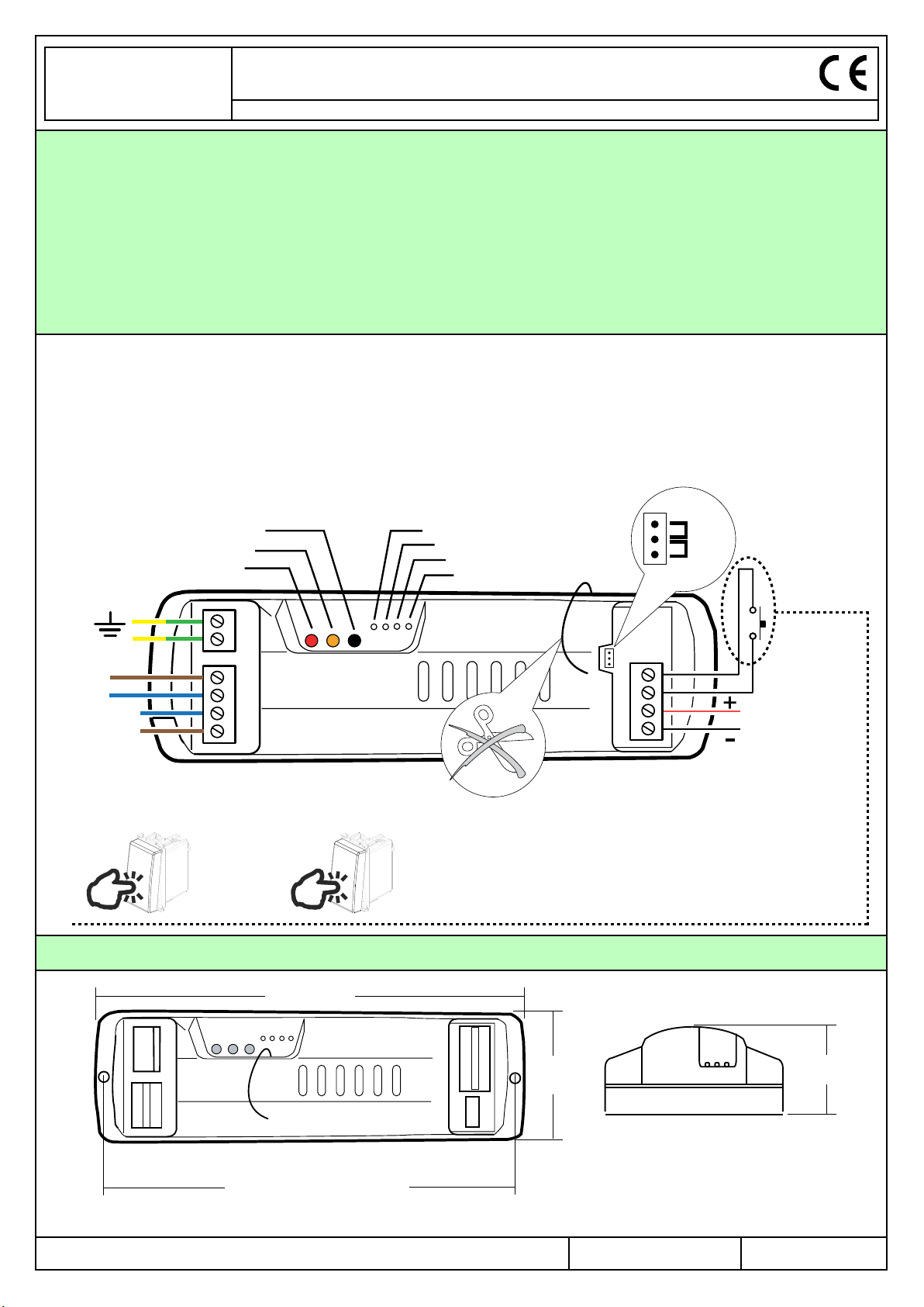
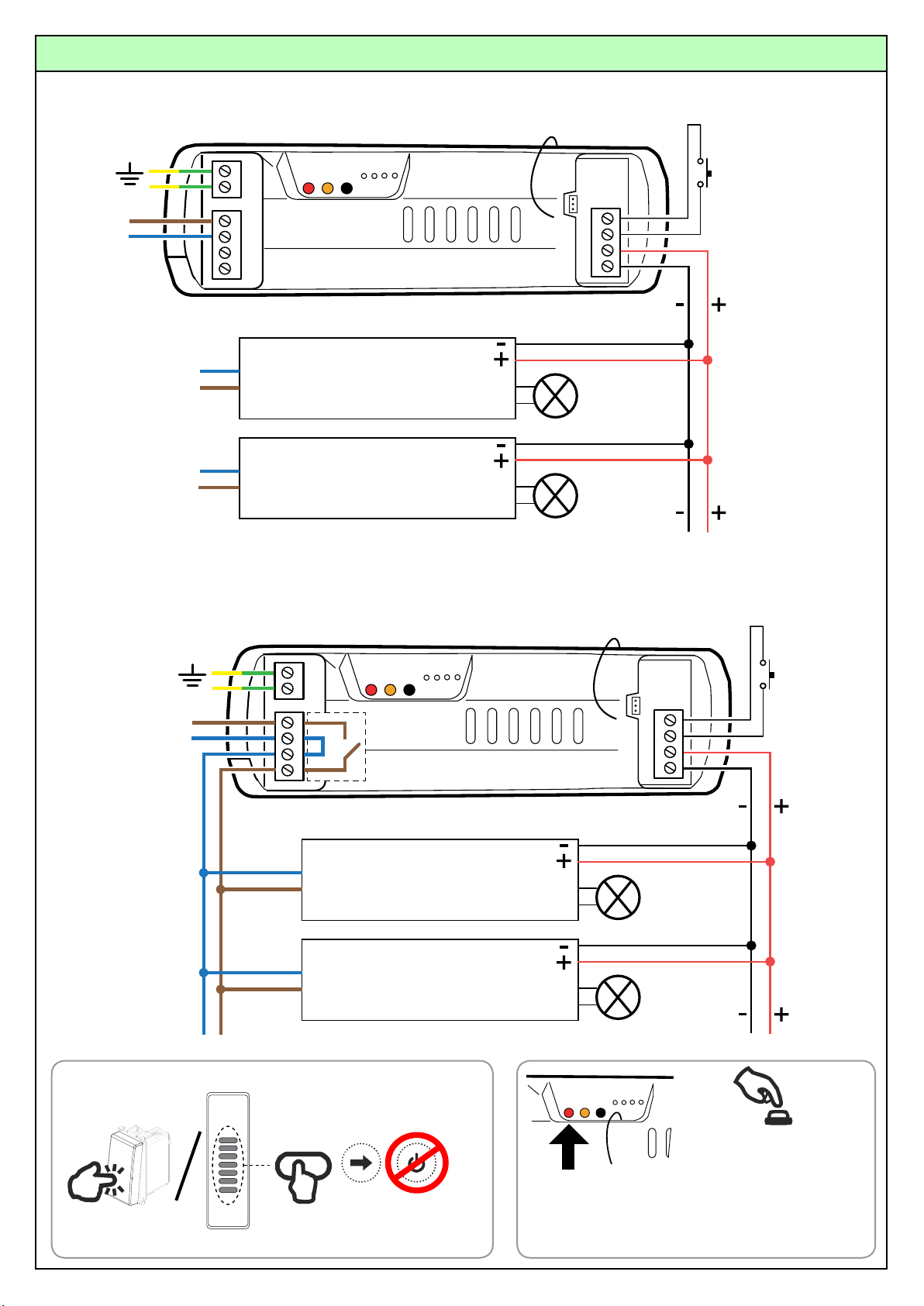
ELECTRICAL CONNECTIONS
All the connections must be rated for a single-phase
230Vac power supply, with the relative Earth
connection. For the disconnection from the power line,
use an all-pole switch with contacts having a
dimension of at least 3.5mm. Arrange all the
necessary safety devices and use only materials
complying with the standard of electrical installations.
The cable must have a section properly rated according
to the load connected. Attention: If any cable is
damaged, it must be immediately replaced by a
qualified person in order to avoid any hazard.
manufacturer reserves the right for changing
technical data and features without prior notice.
SAFETY INFORMATION
Do not operate in the high voltage area of the electronic
board, when it is supplied. Use the product only in
combination with devices which can guarantee a safe
extended time functioning. The radio signal reception of
the device could be disturbed by the presence of
electrical disturbances being transmitted by other
appliances working on the same frequency or if the
product is somehow shielded by metal parts.
PRODUCT DISPOSAL
At the end of this product’s useful life, it must not be
disposed of as domestic waste, but must be taken to a
collection centre for waste electrical and electronic
equipment. It is the user’s responsibility to dispose of this
appliance through the appropriate channels at the end of
its useful life. Failure to do so may incur the penalties
established by laws governing waste disposal.
In the view of a constant development of their
products, the manufacturer reserves the right for
changing technical data and features without prior
notice.

Technical specifications
Power supply 230Vac (TVDMMxxxG10S)
110Vac (TVDMMxxxG10SZ)
Max. output power 0-1/10V 30mA
Maximum load on the 16A relay 800W (TVDMMxxxG10S)
400w (TVDMMxxxG10SZ)
The connection cables must have a section suitable to the maximum load applied to the output, and to the
additional devices connected to the input.
Protection rating IP20
Operating temperature range -20°C / +50°C
Reception frequency 868.3 MHz (TVDMM868G10S)
916 MHz (TVDMM916G10Sx)
Radio memory capability (transmitters) 16
This manual suits for next models
2
Table of contents
Other MR. RESISTOR Receiver manuals