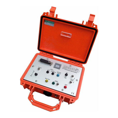
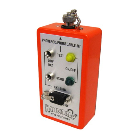
MREL MicroTrap User manual

MREL GROUP OF COMPANIES LIMITED
5-779 Sir John A MacDonald Blvd. Kingston, Ontario K7L 1H3 Canada
Operations Manual
Edition 4.4

MicroTrap™ Operations Manual - Edition 4.4
II
Copyright Information
MREL Group of Companies Limited (MREL) warrants that the product is free from Manufacturer’s defects for a period of one (1) year from
the date of shipment to the Customer. This Warranty covers all parts and labour.
MREL does not warrant that the product will meet the Customer’s requirements, or that it will operate in the combinations which may be
selected by the Customer.
MREL does not and cannot warrant the performance or results that may be obtained by using the product. Accordingly, the product and its
documentation are sold “as is” without warranty as to their performance, merchantability or fitness for any particular purpose. The Customer
assumes the entire risk as to the results and performance of the product.
MREL is committed to product innovation; accordingly product may undergo specification improvements without notice. Copyright ©
2022 MREL Group of Companies Limited. MicroTrap™ VOD/Data Recorder, MicroTrap™ VOD/Data Recorder Logo, and MREL Logo
are trademarks or registered trademarks of MREL Group of Companies Limited. Windows
®
is a registered trademark of Microsoft
Corporation.
© Copyright 2022, MREL Group of Companies Limited. This Operations Manual supersedes any earlier editions. All Rights Reserved.
Reproduction or adaptation of any part of this documentation or Software without written permission of the Copyright owner is unlawful.
Publication History
Edition 4.4, 2022
This version of the Manual
Edition 4.0, March 2014
Edition 3.0, February 2013
Edition 2.2, March 2009
Edition 2.1, January 2009

III
Table of Contents
Chapter 1: Getting Started 1
1.1 MicroTrap™ Hardware Included 2
1.2 Installing the DAS™ Data Acquisition Suite Software 2
1.3 Definitions of VOD Settings 3
Chapter 2: Introduction 5
2.1 Background 6
2.2 Safety Considerations 7
2.3 VOD Applications 7
2.3.1 Testing of Explosive Samples 7
2.3.2 Testing of Explosives in Blastholes 8
2.4 Applications of the MicroTrap™ with Scope Upgrade Installed
8
Chapter 3: Hardware 9
3.1 Hardware Components 10
3.1.1 MicroTrap™ VOD/Data Recorder 10
3.1.2 Carrying Case 15
3.1.3 Battery Charger 16
3.1.4 USB Communications Cable 16
3.1.5 BNC Adapters 16
3.2 Internal Rechargeable Battery 16
3.3 Checking the Power Status 16
3.4 Recharging 17
3.5 Operating the MicroTrap™ from External Power Sources 17
3.6 Long Term Storage Considerations 18
3.7 VOD Resistance Probes 18
3.7.1 VOD ProbeRod 18
3.7.2 VOD ProbeCable 19
3.8 Technical Specifications 20

MicroTrap™ Operations Manual - Edition 4.4
IV
Chapter 4: Recording VOD and Hole/Deck Delay Times 21
4.1 Safety Considerations for Selecting an Explosive Testing Site 22
4.2 The Resistance Wire Technique for Measuring VOD 22
4.3 Using ProbeRods for Testing Samples of Explosives 23
4.4 Using ProbeCable for Testing Explosives in Blastholes 25
4.4.1 Preparation of ProbeCable for Single Blasthole Recording 25
4.4.2 Preparation of ProbeCable for Multiple Blasthole Recording 27
4.5 ProbeCable and Coaxial Cable Protection 28
4.6 MicroTrap™ Setup Procedure for VOD Measurements 30
4.7 Probe Resistance Out of Range Lights 32
4.8 Utilizing the External Trigger 33
4.9 Additional Information on Memory and Triggering 33
4.9.1 Memory 33
4.9.2 Triggering 34
Chapter 5: Recording Voltage Signals From Gauges 39
5.1 Introduction to Recording DC Voltage Signals 40
5.2 Connecting Gauges to the MicroTrap™ VOD/Data Recorder 40
5.3 Signal Cable Protection 41
5.3.1 Detonation Cord 41
5.4 MicroTrap™ Setup Procedure for Recording Voltage Signals 42
5.5 Utilizing the External Trigger 44
5.6 Additional Information on Memory 45
Chapter 6: MicroTrap™ VOD/Data Recorder Software 47
6.1 Retrieving Data 48
6.2 Selecting Data Files for Analysis 48
Chapter 7: Contacting MREL for Technical Support 49
7.1 Contacting MREL 50

MicroTrap™ Operations Manual - Edition 4.4
2
Photographs of these hardware components are contained in Section 3.1.
1. MicroTrap™ VOD/Data Recorder.
2. MicroTrap™ Battery Charger that is labeled 120 VAC or 220 VAC depending on your country’s mains power.
3. Communications Cable - USB cable.
4. BNC Adapters x2.
5. Carrying Case.
6. DAS™ Data Acquisition Suite Operations Software on USB.
7. MicroTrap™ Operations Manual.
8. DAS™ Data Acquisition Suite Manual.
9. If Optional Scope Upgrade has been purchased, an additional 4x BNC Adapters will be included.
10. VOD resistance probes: VOD PROBERODs and/or VOD PROBECABLE and/or VOD PROBECABLE-LR. (Optional)
1.1 MicroTrap™ Hardware Included
All of the steps detailed in this Chapter should be completed before the Operator goes into
the field to conduct a VOD test:
1. Ensure that all MicroTrap™ components have been received and are available.
2. Ensure that the DAS™ Data Acquisition Suite is installed and operational according to the
DAS™ Data Acquisition Suite Software manual.
3. Ensure that the Operator’s computer and MicroTrap™ are able to communicate with
each other.
4. Program the MicroTrap’s internal recording parameters using the MicroTrap™ Software.
Refer to the DAS™ Data Acquisition Suite Manual for installation procedure.
Overview
1.2 Installing The DAS™ Data Acquisition Suite Software

3
1.3
Definitions of VOD Settings
This section will discuss the meaning of each setting.
Trigger Level is the threshold that the signal will cross to indicate a valid trigger. For VOD, the typical setting for Trigger Level is 95%.
Pre-Trigger Time is the amount of time of the Total Time available for each test that will be captured prior to the trigger point. For VOD, the typical
setting for Pre-Trigger Time is 25%
Number of Tests is a number from 1 to 16 that the total memory of the unit is divided into. The lower the Number of Tests, the larger number of
points will be recorded per test. The user needs to ensure that the amount of time is sufficient to capture the test which includes the amount of Pre-
Trigger Time and the Total Time.
Recording Rate is the number of points captured per second. The faster the Recording Rate, the shorter the amount of time within each test. For
VOD, the typical setting for Recording Rate is 1 MHz or or 2 MHz.
External Trigger is the setting that will allow the user to use an external source to have a valid trigger. There are two ways for the
MicroTrap™
VOD/Data Recorder
to receive an External Trigger.
• Make Circuit uses a loop of wire that is normally open circuit and triggers the
MicroTrap™
when the circuit closes.
• Break Circuit uses a loop of wire that is normally closed circuit and triggers the MicroTrap™ when the circuit opens.
For more details on the External Trigger feature, refer to Section 5.5.
To use External Trigger, ensure that the switch on the panel has been set to External prior to pressing the Start button.

MicroTrap™ Operations Manual - Edition 4.4
4

MicroTrap™ Operations Manual - Edition 4.4
6
The MicroTrap™ VOD/Data Recorder is a portable, 1 channel, high resolution, explosives continuous Velocity of Detonation (VOD)
recorder. It can be upgraded easily to provide an additional 4 channels of DC voltage (VDC) recording (Scope) capability. The operator
can use DAS™ Data Acquisition Suite Software to check if the unit has the Scope Upgrade installed during programming of the unit.
Contact MREL for MicroTrap™ VOD/Data Recorder Scope Upgrade information. This provides the MicroTrap™ VOD/Data Recorder with
the ability to record high resolution VODs of explosives and simultaneously record transient events such as blast vibrations, explosion
pressures, air blast, etc. at high resolutions. It has proven its reliability under the extreme temperature, weather, dust and rugged
conditions that characterize blasting environments around the world.
The DAS™ Data Acquisition Suite allows the User to analyze VOD traces and convert DC voltage signals recorded by the MicroTrap™
VOD/Data Recorder into the desired engineering units for analysis and presentation. The software is used to program the recording
parameters of the MicroTrap™ VOD/Data Recorder, and to retrieve, display, analyze, print, and export VOD or other sensor data
obtained through testing. The DAS™ Data Acquisition Suite Software runs under 32 or 64 bit Microsoft Windows®. This facilitates
extremely fast data handling, and the ability to copy and paste graphs into any word processors or spreadsheets running in the
Windows® environment. Refer to the DAS™ Data Acquisition Suite Software for more information.
The main features of the MicroTrap™ VOD/Data Recorder for VOD recording are:
• One VOD channel capable of recording at up to 2 MHz (2 million data points/sec). This speed provides a time resolution of one
data point for every 0.5 microseconds.
• Capability to record VODs and delay times using up to 900 m (2,950 ft.) of MREL’s PROBECABLE-LR VOD resistance cable. This
ensures that the MicroTrap™ can record the VODs and delay times in many blastholes per test.
• A large, circular, digital memory (4 million data points) to store the recorded data. This allows the MicroTrap™ VOD/Data Recorder
to record for relatively long periods (2.0 seconds) when recording at a rate of 2 MHz. The memory can be upgraded easily to
provide a total memory of 8 million data points. Contact MREL for MicroTrap™ Memory Upgrade information.
• A high, 14 bit vertical (or distance) resolution (214 or 1 part in 16,384). Use of shorter lengths of PROBECABLE-LR provides even more
data points recorded along every meter.
• Large non-volatile memory for storing up to 16 events before the data needs to be downloaded to a computer.
• Data is downloaded to the PC via the supplied USB cable.
• The MicroTrap™ VOD/Data Recorder can be upgraded easily to provide an additional 4 channels of DC voltage recording
capabilities at a recording rate of 1 MHz. Contact MREL for MicroTrap™ Scope Upgrade information.
• The status of the MicroTrap™ Memory and Scope Upgrade for each MicroTrap™ VOD/Data Recorder can be found when the unit is
connected to DAS™ Data Acquisition Suite Software. Please refer to the DAS™ Data Acquisition Suite Manual for the location of this
information for each unit.
2.1 Background
This Chapter provides an introduction to the MicroTrap™ VOD/Data Recorder.
Overview

7
2.2 Safety Considerations
The MicroTrap™ VOD/Data Recorder is an easy and safe instrument to operate. However, one should be aware of the inherent risk
associated with explosives handling and familiar with working in blasting environments. For this reason, it is always recommended that
only knowledgeable personnel, experienced in handling explosives and familiar with blasting procedures, operate the MicroTrap™
VOD/Data Recorder when testing explosives. The standard rules of safety used with explosives should apply when monitoring VODs or
other explosive parameters.
When recording VODs, the MicroTrap™ VOD/Data Recorder outputs a low voltage (less than 8 V DC) and an extremely low current (less
than 50 mA) to the probes within the explosives from the VOD connector on the MicroTrap™ VOD/Data Recorder. This low excitation
signal ensures that the MicroTrap™ will not prematurely initiate explosives and/or detonators. With the optional MicroTrap™ Scope
Upgrade installed, the MicroTrap™’s Scope channels do not output any excitation voltage or signal.
Standard (and common sense) rules apply when it comes to the presence of electrical storms near the testing area. Due to the inherent
hazards associated with blasting during these storms, in addition to the possibility of electrical interference causing false trigger signals
to the MicroTrap™ VOD/Data Recorder, it is recommended to immediately suspend all blasting activities and evacuate the area. This is
standard policy at most blasting operations.
2.3 VOD Applications
When used as a VOD recorder, the main applications of the MicroTrap™ VOD/Data Recorder include:
2.3.1 Testing of Explosive Samples
• Test the performance of explosives against the quality control standards stated by the manufacturer.
• Measure the continuous VOD in any charge diameter under confined or unconfined conditions.
• Determine the critical diameter and critical density of an explosive charge.
• Determine the gap sensitivity of explosives.
• Measure the timing accuracy of detonators.
• Measure the continuous VOD of primers/boosters.
• Determine the minimum booster size for any explosive by measuring run-up velocities.
STOP
Persons not trained and/or authorized to handle explosives should not attempt to utilize the MicroTrap™ VOD/Data
Recorder for monitoring explosive properties.

MicroTrap™ Operations Manual - Edition 4.4
8
2.3.2 Testing of Explosives in Blastholes
• Measure the continuous VOD in any hole diameter, wet or dry holes, and in any type of rock.
• Measure the continuous VOD in multiple holes per blast.
• Determine whether full detonation, low order detonation or failure occurred, and where in the explosive column it happened.
• Check VODs against manufacturers’ specifications in full scale blasting environments.
• Determine the minimum booster size for any explosive by measuring run-up velocities in full scale blasting environments.
• Measure the timing accuracy of detonators in full scale blasting environments.
• Measure the effects of water, drill cuttings, and rocks, etc. trapped within the explosive mass.
• Determine the length of explosive column to use in decking operations to evaluate the effect of stemming and drill cutting dilution,
water pick-up, etc. on the explosive run-up requirements.
• Determine the correct length and type of stemming material to be used between decks of explosives to prevent sympathetic
detonation or explosive desensitization from occurring.
2.4 Applications Of MicroTrap™ with Scope
Upgrade Installed
As previously mentioned, with the Scope Upgrade, the MicroTrap™ VOD/Data Recorder has the ability to function as a digital
oscilloscope recording device to record DC voltage signals from a wide variety of commercially available sensors. DC voltage and VOD
can be recorded simultaneously. Typical applications of the MicroTrap™ VOD/Data Recorder when used as a data recorder include
(external power sources may be required):
• Measurement of detonation pressure using calibrated PVDF (polyvinylidene fluoride) gauges.
• Measurement of air blast over-pressures using commercially available air blast pressure transducers.
• Measurement of cross-blasthole pressures using carbon composition resistors and/or commercially available tourmaline gauges.
• Measurement of blasting vibrations using geophones or accelerometer transducers.
• Measurement of temperature using thermocouples.
• Measurement of any phenomena that can be instrumented with gauges producing DC voltage signals in the range from
-10 to +10 volts.

MicroTrap™ Operations Manual - Edition 4.4
10
This Chapter describes all of the hardware components provided with the MicroTrap™
VOD/Data Recorder.
3.1 Hardware Components
The hardware components of the MicroTrap™ VOD/Data Recorder System include the MicroTrap™ VOD/Data Recorder, a Carrying Case,
a Battery Charger, a USB Communications Cable and two (2) BNC Adapters. If the MicroTrap™ VOD/Data Recorder Scope Upgrade has
been installed, there are four (4) additional BNC Adapters provided. Also included with the MicroTrap™ VOD/Data Recorder System
is this Operations Manual and the DAS™ Data Acquisition Suite Manual. A brief description of each of the hardware components
is in the following sections.
3.1.1 MicroTrap™ VOD/Data Recorder
The MicroTrap™ VOD/Data Recorder contains electronic circuitry and an internal rechargeable battery
within a protective plastic case measuring approximately 21 x 17 x 9 cm
(8.3 x 6.7 x 3.5 in) and weighing 2 kg (4.4 lbs). The protective case prevents damage from water,
sand, snow, dust and similar harsh weather conditions. As well, the case offers resistance to high
temperatures, shocks and vibrations. The MicroTrap™ VOD/Data Recorders front panel is shown on
the following page.
Complete instructions for the field operation of the MicroTrap™ VOD/Data Recorder
hardware are provided in Chapter 4. The main features of the control panel are
outlined below:
MAIN CONTROL PANEL
Power:
The ON/OFF switch is used to provide power to the MicroTrap™ VOD/Data Recorder.
Status Light:
The STATUS indicator light has three working modes:
In Active mode, the light is illuminated, indicating that the MicroTrap™ VOD/Data Recorder is ready for the User to press the START
button. When the START button is pressed it enters Monitoring mode, which starts recording in the circular memory. When the trigger
criteria has been met, the MicroTrap™ VOD/Data Recorder will record the final loop of data, including the pre-set pre-trigger amount
dictated by the User when programming the MicroTrap™ VOD/Data Recorder.
In Stand-by mode, the light flashes slowly, indicating that the MicroTrap™ VOD/Data Recorder has finished collecting and storing data.
In Stand-by mode, the MicroTrap™ VOD/Data Recorder is waiting for the User to either switch power OFF; press the NEXT TEST button (to
go to Active mode); or download the data to a computer. If the data will be downloaded the same day, the best practice is to leave the
unit powered on.
Overview
CAUTION
The Power switch must remain in its position for more than 5 seconds before it is changed back. Do not turn it on and
off quickly to check the battery status. It must fully start. If this is not followed, an unrecoverable error can occur and
the unit may be required to be sent in for service.

11
LED Display:
The LED screen is a two-digit display designed to report the status of the internal battery, the total number of tests programmed by the
DAS™ Data Acquisition Suite , and the number of tests remaining to be filled. The LED screen also displays special characters when
advanced operations are being performed.
Battery Level:
The BATTERY STATUS button is pressed to display the battery level on the LED screen. The MicroTrap™ VOD/Data Recorders battery level
is displayed in integers from 0 to 10. Full battery is displayed as 10. A battery level of 8 would represent 80% charge remaining.
ON/OFF Switch
STATUS Indictator
MICROTRAP USB COM
TOTAL TESTS Button
NEXT TEST Button
REMAINING TESTS Button
STOP Button
OUT OF RANGE Lights
TRIG EXT/INT Switch
START Button and Indictator
BATTERY STATUS Button
LED Screen

MicroTrap™ Operations Manual - Edition 4.4
12
Total Tests:
The TOTAL TESTS button is pressed to display the total number of tests that the MicroTrap™ VOD/Data Recorder memory has been divided
into. The total number of tests can be set using the DAS™ Data Acquisition Suite Software. Please refer to DAS™ Data Acquisition Suite
Software Manual for instructions on programming the MicroTrap™ VOD/Data Recorder.
Remaining Tests:
The REMAINING TESTS button is pressed to display the number of programmed memory spaces that have yet to be filled with test data.
This number represents the difference between the total number of tests, and the number of tests already conducted and stored in the
MicroTrap™ VOD/Data Recorder’s memory.
Deleting Test Data:
The TOTAL TESTS and REMAINING TESTS buttons also have an advanced function. They can be used by the Operator to erase the data
recorded in the last test from the MicroTrap™ VOD/Data Recorders memory using hardware alone as opposed to using the DAS™ Data
Acquisition Suite, as detailed in DAS™ Data Acquisition Suite Software Manual.
• Do not turn OFF the MicroTrap™ VOD/Data Recorder after the test, the STATUS light and TRIG’D lights should be flashing.
• To erase the data from the last test; simultaneously press the TOTAL TESTS and REMAINING TESTS buttons and hold them until this
procedure is complete. The LED display will show ct. After about 2 seconds, the ct will begin blinking. After another 2 seconds, the ct
will disappear. Release the buttons. The data from the last test has been deleted.
• Turn OFF the MicroTrap™ VOD/Data Recorder. Turn ON the MicroTrap™ and press the TOTAL TESTS button and then the REMAINING
TESTS button. This will confirm that the remaining tests have been increased by 1 and that the last test in the MicroTrap™ VOD/Data
Recorders memory has been deleted.
Trigger Selection:
The TRIG EXT/INT switch selects internal (INT) or external (EXT) triggering of the MicroTrap™. Using the DAS™ Data Acquisition Suite
Software, the internal Trigger Level and Pre-Trigger memory allocation can be set. The External Trigger mode can be set using the
software by selecting either “BREAK circuit” or “MAKE circuit” external triggers. The position of this switch is captured in the settings
when the START button is pressed. After the START button is pressed, moving this switch will have no effect on the settings. Triggering is
described in detail in Chapter 4.8 and Chapter 4.9.
Next Test:
The NEXT TEST button is used to change the MicroTrap™ VOD/Data Recorders mode from Stand-by to Active. When in Active mode, the
MicroTrap™ VOD/Data Recorder waits for the User to press the START button.
Start Button:
When START is pressed, the MicroTrap™ VOD/Data Recorder enters Monitoring mode, which starts recording in the circular memory.
When the trigger criteria has been met, the MicroTrap™ VOD/Data Recorder will record the final loop of data, including the pre-set
pre-trigger amount dictated by the User when programming the MicroTrap™ VOD/Data Recorder. When the START button is pressed,
the START light illuminates. If the TRIG EXT/INT switch is set to EXT and the external trigger mode is set to “BREAK circuit” and nothing is
CAUTION
MREL recommends the above procedure for times in which the MicroTrap™ VOD/Data Recorder triggers prematurely
when the Operator is setting up the MicroTrap™ VOD/Data Recorder to record a VOD test. Premature triggering can
be caused by situations such as: loose connections in the signal wires; excessive moving of or driving over the signal
wires; or by the Operator inadvertently triggering the MicroTrap™ when using an external trigger wire.

13
connected to the EXT TRIG BNC, the MicroTrap™ VOD/Data Recorder will trigger immediately when START is pressed. This is a common
error for first time users. If the OUT OF RANGE Low or High lights are illuminated, the START button will not allow the test to start (and the
START light to illuminate).
Stop Button:
The STOP button is particularly useful when the MicroTrap™ VOD/Data Recorder has been set at a very slow sampling rate using
DAS™ Data Acquisition Suite Software. An example of this would be using a thermocouple sensor in a long-duration experiment with a
MicroTrap™ VOD/Data Recorder that has had the MicroTrap™ VOD/Data Recorder Scope Upgrade installed. Given the large memory
in the MicroTrap™ VOD/Data Recorder, if the lowest sampling rate (1 Hz) is selected, a total recording time of 4 million data points / 1
Hz = 4,000,000 seconds (46 days) will be available for recording. After the User is satisfied that the pertinent data has been recorded,
pressing the STOP button marks the remaining data as unused, and the MicroTrap™ VOD/Data Recorder will then revert back to Stand-by
mode. This saves the User from having to wait for the MicroTrap™ VOD/Data Recorder to finish the test automatically. If the MicroTrap™
VOD/Data Recorder did not trigger, the User can press the STOP button to allow the diagnostic of the saved file for the possible reason
that the unit did not trigger. When the file is opened, choose “Hide uninitialized memory” to not display the data that was not captured.
Erasing All Tests:
The STOP button also has an advanced function. It can be used as part of a sequence to manually erase all of the data in the
MicroTrap™ VOD/Data Recorders memory in the absence of a PC. This can be performed in the following steps:
1. Turn ON the MicroTrap™ VOD/Data Recorder.
2. Press the NEXT TEST button to put the MicroTrap™ VOD/Data Recorder in Active mode. The STATUS light should be on.
3. Simultaneously press the NEXT TEST and STOP buttons and hold them down. The LED will display a blinking dE. Release the buttons.
4. Simultaneously press the START and STOP buttons and hold them down. The LED will display dE without blinking. Release the
buttons. All of the data in the MicroTrap™ VOD/Data Recorders memory will be deleted.
5. Turn OFF the MicroTrap™. Wait 5 seconds. Turn ON the MicroTrap™ VOD/Data Recorder then press the TOTAL TESTS button and then
the REMAINING TESTS button to confirm that these numbers are equal and that all of the test data in the MicroTrap™
VOD/Data Recorders memory has been deleted.
MICROTRAP USB COM:
The MICROTRAP USB COM port is used to connect the Communications Cable to the MicroTrap™ VOD/Data Recorder. The other end
of the Communications Cable is connected to the USB Port of the computer, for programming the internal Recording Parameters of the
MicroTrap™ VOD/Data Recorder and for retrieval of the recorded data (Section 5.1). See the DAS™ Data Acquisition Suite Software
Manual for performing this task.
Out of Range Lights:
There are two OUT OF RANGE warning lights. They will flash when the probe resistance is out of range as discussed in Chapter 4.7.
CAUTION
MREL recommends the above procedure for times in which the Operator is already in the
field and has forgotten to Clear All Tests using the MREL DAS™ Data Acquisition Suite.
CAUTION
The unit must be powered on for at least 5 seconds prior to connecting the USB cable. If this is not followed, an
unrecoverable error can occur and the unit may be required to be sent in for service.

MicroTrap™ Operations Manual - Edition 4.4
14
BACK PANEL
The back of the MicroTrap™ VOD/Data Recorder has a variety of input and output ports that are described below:
VOD:
BNC connector for the VOD resistance probe.
EXT TRIG:
BNC connector for the trigger wire, if external triggering is used.
TRIG OUT:
BNC connector that produces a voltage signal of 10 volts for 6 seconds when the MicroTrap™ VOD/Data Recorder is triggered. This
signal is used to trigger other instrumentation.
DC IN/OUT:
Used to connect the MicroTrap™ VOD/Data Recorder to the Battery Charger to recharge the internal battery, and to operate the
MicroTrap™ VOD/Data Recorder from AC mains power. The DC IN/OUT port can also be used to power the MicroTrap™ VOD/Data
Recorder from an external 12 VDC battery using the current limiting adapter that is supplied by MREL. It can also be used to supply 10
VDC as an excitation source for other types of gauges. All details and restrictions on use of the DC IN/OUT connector are contained in
Section 3.4 and Section 3.5.
1 2 3 4:
BNC connectors for Channels 1, 2, 3 and 4of the optional MicroTrap™ VOD/Data Recorder Scope Upgrade. These connectors have no
function unless the MicroTrap™ VOD/Data Recorder Scope Upgrade has been installed.
VOD Connector
EXT TRIG Connector
1 2 3 4 Connectors
DC IN/OUT Connector
TRIG OUT Connector

15
FRONT PANEL
TRIG’D:
The TRIG’D indicator light on the front of the MicroTrap™ VOD/Data Recorder will illuminate when the trigger conditions are met. It will
remain illuminated during collection of the data, which depends on the recording rate selected for the test. The TRIG’D light flashes rapidly
while the data is being stored in the MicroTrap™ VOD/Data Recorder’s non-volatile memory. The TRIG’D light flashes slowly after all data
from the test has been stored in the MicroTrap™ VOD/Data Recorder’s memory. Otherwise, the light will remain off.
BLACK VENT:
The black knob on the front of the MicroTrap™ VOD/Data Recorder is an automatic pressure relief valve. When transporting the
MicroTrap™ VOD/Data Recorder by air, this valve allows pressure equalization upon landing. At high altitudes the internal pressure of the
MicroTrap™ VOD/Data Recorder may drop, causing a negative air pressure at ground elevation which makes the lid very difficult to open
without this pressure equalization valve.
3.1.2 Carrying Case
The Carrying Case holds the MicroTrap™ VOD/Data Recorder, Battery Charger, Communications
Cable and BNC Adapters.
Black Vent
TRIG’D Indicator

MicroTrap™ Operations Manual - Edition 4.4
16
3.1.3 Battery Charger
The Battery Charger has a specification printed on it, either 120 VAC or 220 VAC. It is used to charge
the internal rechargeable battery, and it can be used to operate the MicroTrap™ VOD/Data Recorder
from AC mains.
3.1.4 USB Communications Cable
The Communications Cable is provided to connect the MicroTrap™ VOD/Data Recorder to a computer for
programming the recording parameters of the MicroTrap™ VOD/Data Recorder and for downloading of the
recorded data. The Communications Cable is connected between the MICROTRAP USB COM port on the front
panel and a USB port of the computer. This is a specific cable that is required for the communication of the unit.
Generic USB to parallel adapters will not work with the MicroTrap™ VOD/Data Recorder.
3.1.5 BNC Adapters
Two BNC Adapters are provided to facilitate easy connection between the VOD and EXT TRIG
connectors on the MicroTrap™ VOD/Data Recorder to the coaxial cable (preferably RG-58
leading to the VOD probe, and the external trigger wire, respectively. If the MicroTrap™ VOD/
Data Recorder Scope Upgrade has been installed, four additional BNC Adapters are provided,
one for each Scope input channel.
3.2 Internal Rechargeable Battery
The MicroTrap™ VOD/Data Recorder has an internal Ni-Cad rechargeable battery. The MicroTrap™ VOD/Data Recorder is supplied
with an approved 120 VAC or approved 220 VAC Battery Charger, depending on the country of use. When the internal battery is
fully charged, the MicroTrap™ VOD/Data Recorder can operate for 12 hours (at maximum MicroTrap™ VOD/Data Recorder power
consumption) before battery recharging is required. The MicroTrap™ VOD/Data Recorder is shipped from MREL fully charged. Since
some time may elapse before the MicroTrap™ VOD/Data Recorder is actually put to use, the MicroTrap™ VOD/Data Recorder may not be
charged fully the first time it is used. Full operating time will be obtained when the MicroTrap™ VOD/Data Recorder is recharged.
3.3 Checking the Power Status
The procedure to check the power status of the MicroTrap™ VOD/Data Recorder is as follows:
1. Turn the MicroTrap™ VOD/Data Recorder switch to the ON position. Wait for 5 seconds until the STATUS light enters Stand-by
mode and then, press the BATTERY STATUS button on the front panel. This button can be pressed at any time during operation of the
MicroTrap™ VOD/Data Recorder.
2.
STOP
Contact MREL if the Battery Charger that has been supplied
is incorrect for the mains voltage in your country.
Other manuals for MicroTrap
2
Table of contents
Other MREL Measuring Instrument manuals