Depending on the Luminator battery
used, the cap lamp is designed to
operate at full brilliance for a minimum
of an 8-10 hour shift, with reserve
energy if needed. At the end of each
shift the battery is recharged in a sin-
gle- or multiple-station charging unit.
The Luminator Power Cell (13 AH) is
designed to operate at cycle routines
of 8-10 hours discharge/16-14 hour
recharge 5 days/week (max). If the
routines are increased, the Luminator
Power Cell Plus (16 AH) is recom-
mended. Battery charging connection
is made through the headpiece, using
either a parallel or modular charging
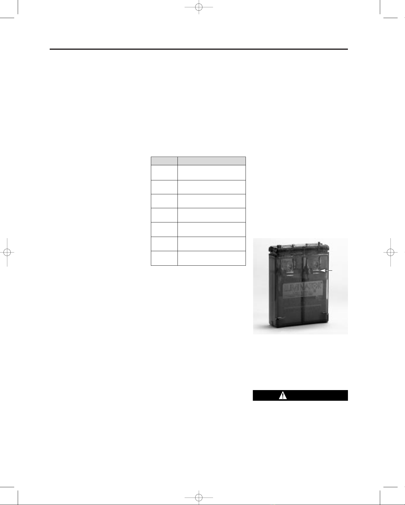
system. Each battery has a transpar-
ent case with molded-in electrolyte
level indicators below the filling ports.
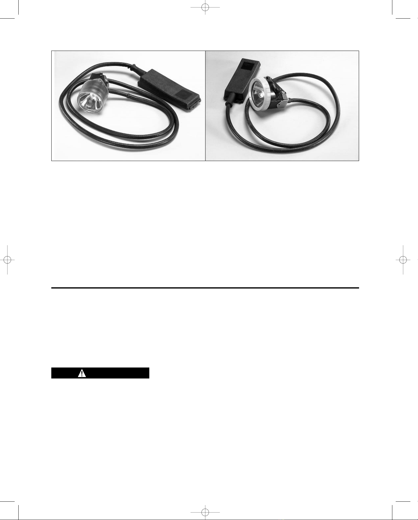
Remote Power Connections
The Remote Power Connection allows
the Cap Lamp to be used as a power
source for an external remote device
while still operating as light source.
MSHA regulation permits this configu-
ration as long as the external remote
device current requirement does not
exceed 275 milliamps.
If using the Remote with the Ultralight
or ML-2 Cap lamps, the Luminator
Power Cell Plus 16 Ah battery is rec-
ommended, due to higher battery
demands. However, the Luminator
Power Cell 13 AH has been approved
with the Remote Power Connection
for Ultralight Cap Lamp use only.
Preparing the Ultralight and ML-2
Cap Lamps for First Time Use
Battery Charging
Every battery must be charged before
it is used for the first time. A battery
may be charged with parallel or modu-
lar systems, in either standard or low
profile racks, or in a single station
charger. Various MSA chargers and
part numbers are listed in the chart
below:
1. Set power supply or charging sta-
tions to 5.0 ± .05 VDC.
2. Connect the battery to the charg-
ing station, following the instruc-
tions supplied with the charger.
3. To check that charging current is
flowing, look at the meter (located
either just above or just below the
battery on rack-mounted charg-
ers). The meter needle should
swing to the far right.
Note
In some cases there will not be a
meter on the charger. See the instruc-
tions for the appropriate charger.
4. Allow the battery to remain on
charge for 24 hours.
5. As the battery charges, the meter
needle should gradually move to
the left to OFF. In other chargers,
the LED lights will indicate
charged condition.
6. Top off each cell with distilled water
if necessary (see Watering section).
Routine Battery Maintenance
1. Routine Charging on Standard
Rack and Charger. All batteries in
this category must be charged
immediately after each period of
use in the following manner:
a. Set power supply or charging
stations to 5.0 ± .05 VDC.
b. Connect the battery to the
charging station following the
instructions supplied with the
charger.
c. Check meter, the needle
should swing to right indicating
charge, (or check LED lights).
d. Allow battery to remain in the
rack until it is recharged.
(Needle of meter will return to
“OFF” or LED lights will indi-
cate charged condition).
e. To remove lamp and stop
charge, rotate the headpiece
counterclockwise to a full stop,
then lift headpiece from key and
battery form the charging rack.
Note
Batteries which do not perform satis-
factorily, should be removed from ser-
vice and cycled - charged 16 hours,
discharged 8 hours. Repeat several
times until battery responds. If battery
does not respond after three or four
cycles, it should be replaced.
f. After weekly shifts, the battery
should be placed on the
charger following the instruc-
tions included with the charg-
er, and left to charge the
remainder of the weekend.
g. If cap lamp needs cleaning,
use a mild detergent and wipe.
Do not submerge.
2. Storage of Batteries.
All stored batteries with acid
should be boost charged for 24
hours every 3 months, and imme-
diately before being placed into
regular service. Recommended
storage temperatures 32˚F to 80˚F.
3. Watering.
The electrolyte level should be
maintained between the two lines
indicated below the filling and
venting hole i.e. slightly above the
top of the battery plate.
Normally topping up should not be
necessary more often than once
every 3-4 weeks, and should
always be carried out when the
battery is fully charged. Only dis-
tilled or deionized water should be
used in topping up.
The Electrolyte is corrosive and can
cause burns. Take proper precau-
tions to avoid skin and eye contact.
Contact MSA for battery Materials
Safety Data Sheet (MSDS). Phone
1-800-MSA-2222.
TAL 998 (L) Rev. 2 - 817184 3
General Description