MSA UT-S User manual

Limited Liability Company
“NPK MORSVYAZAVTOMATICA”
26E, Kibalchicha str., 192174,
St. Petersburg, Russia
www.unicont.com
Phone.: +7 (812) 622-23-10
Fax: +7 (812) 362-76-36
MARINE HEATERS
UT-S, UT-C
Operating manual

Version 1.0 2
Marine heaters
UT-S, UT-C
TABLE OF CONTENTS
INTRODUCTION.........................................................................................................................3
1DESCRIPTION AND OPERATION OF THE PRODUCT.................................................4
1.1 Description ...............................................................................................................................4
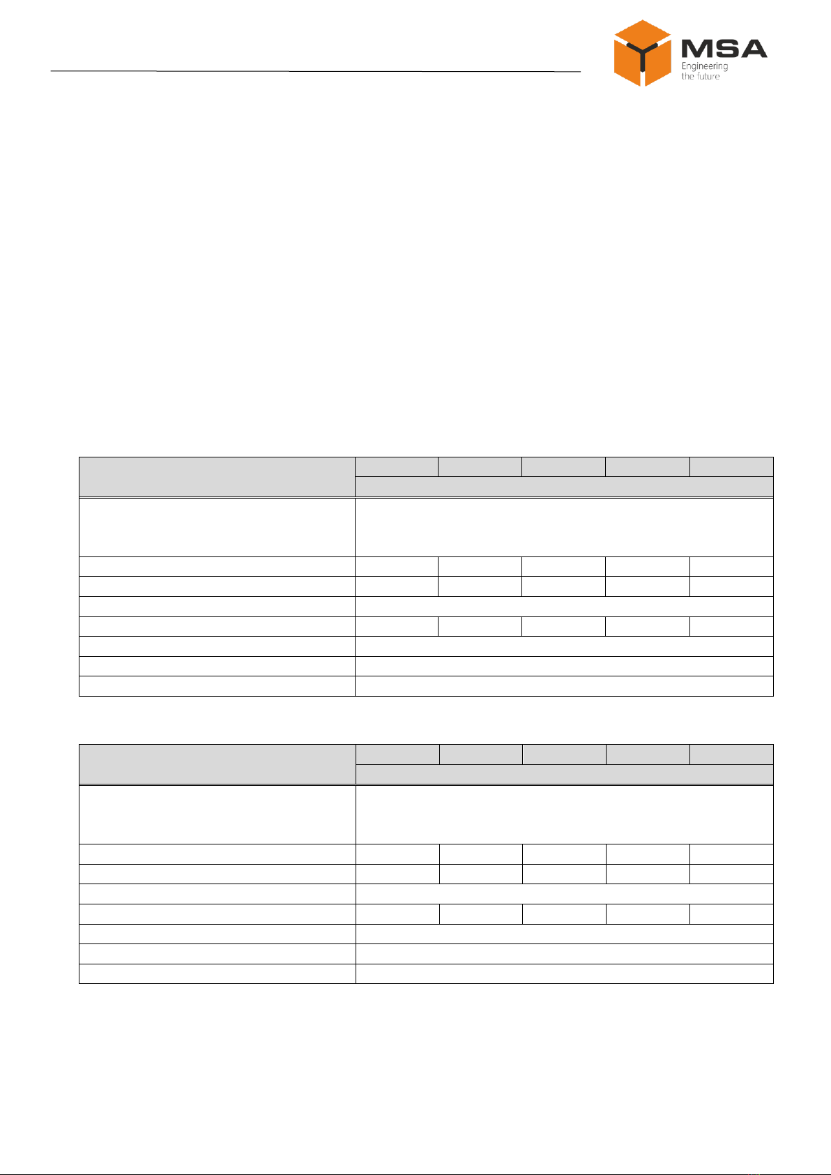
1.2 Technical specifications ...........................................................................................................4
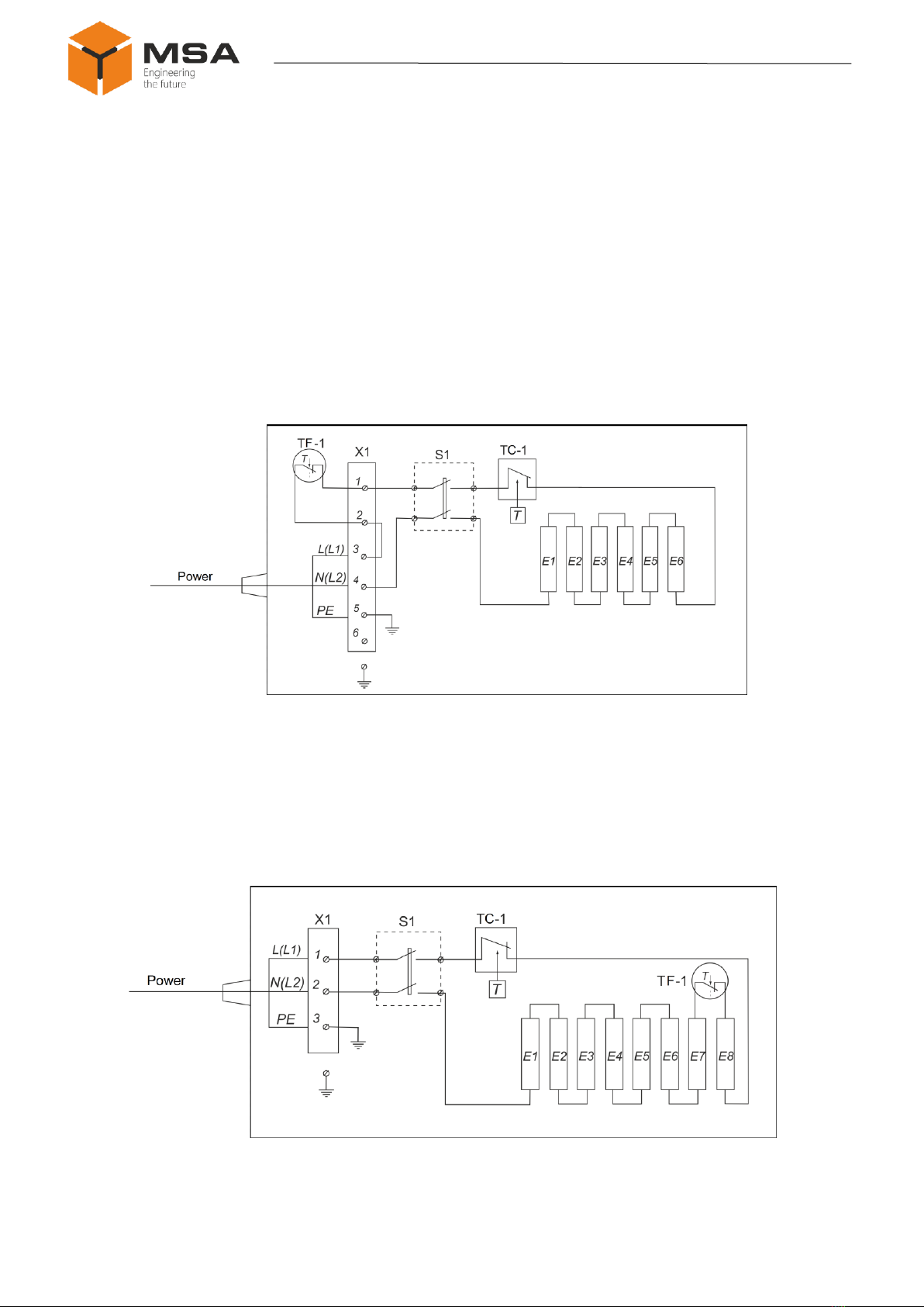
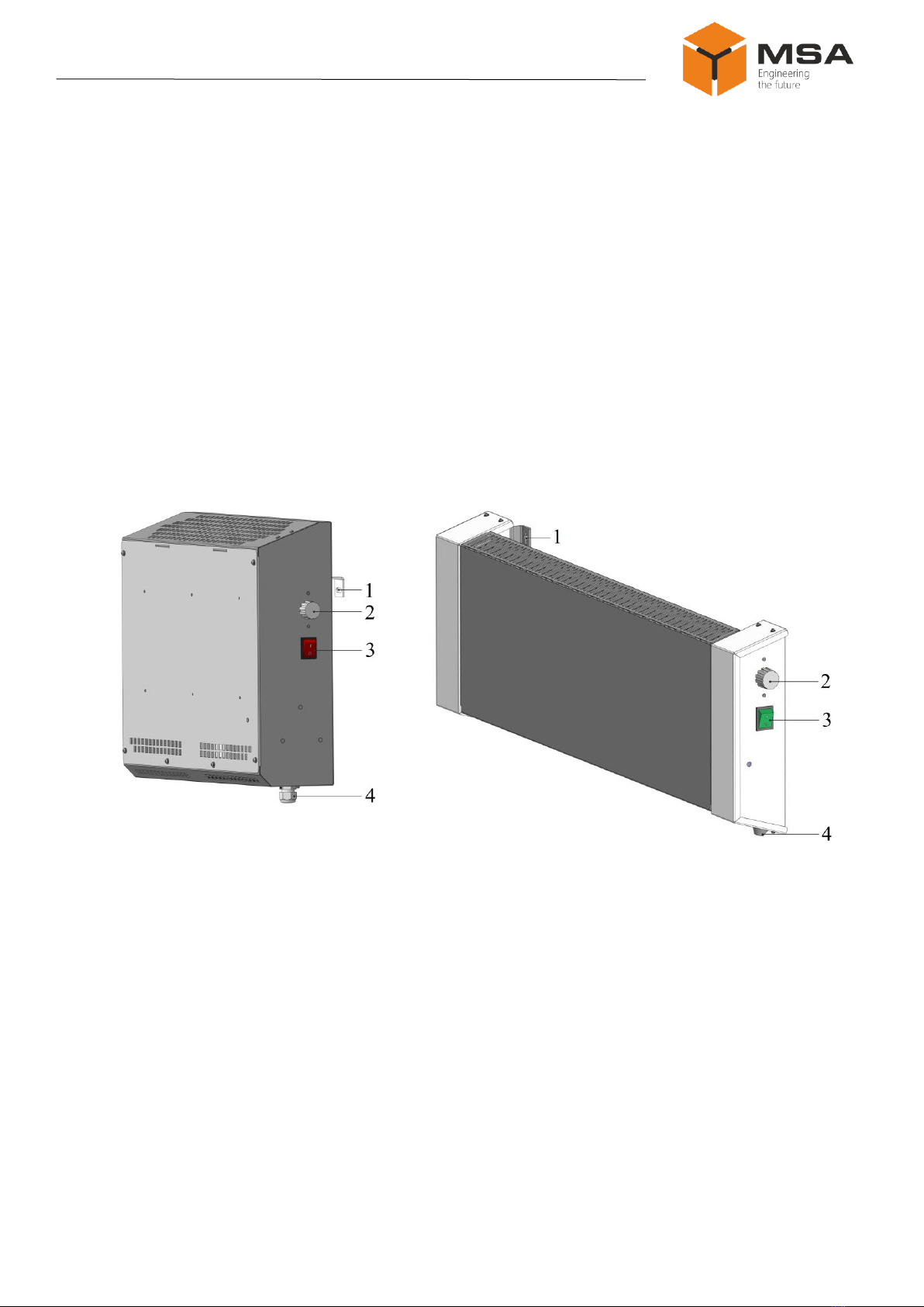
1.3 The Product’s structure and operation......................................................................................5
1.4 Measurement tools, instruments and appliances......................................................................7
1.5 Marking and sealing.................................................................................................................7
1.6 Packaging .................................................................................................................................7
2INTENDED USE.......................................................................................................................8
2.1 Operational constraints.............................................................................................................8
2.2 Preparation for the Product operation.......................................................................................8
2.3 Usage of the Product ................................................................................................................9
3TECHNICAL SERVICE OF THE PRODUCT...................................................................13
3.1 General instructions................................................................................................................13
3.2 Safety features ........................................................................................................................13
3.3 Maintenance routine...............................................................................................................13
3.4 Preservation............................................................................................................................15
4CURRENT REPAIR OF THE PRODUCT..........................................................................16
4.1 General description.................................................................................................................16
4.2 Safety features ........................................................................................................................16
4.3 Сurrent repair..........................................................................................................................16
5STORAGE .............................................................................................................................17
6TRANSPORTATION.............................................................................................................18
7DISPOSAL .............................................................................................................................19
8WARRANTY ..........................................................................................................................20
ANNEX А OUTLINE AND INSTALLATION DIMENSIONS OF THE PRODUCT.........21

3 Version 1.0
Operating Manual
INTRODUCTION
This operating manual (hereinafter referred to as the OM) covers structure,
construction, specifications of Marine heaters type UT-S, UT-C (hereinafter referred to
as the Product), its components and instructions required for the Product’s correct and
safe operation (intended use, technical service, current repair), as well as disposal
information for its components.
Only those who have read operational documentation shall be permitted to
operate the Product.
Only those who have had general education in the area of electronic devices
and read operational documentation shall be permitted to provide the Product’s
service.
TERMS AND ABBREVIATIONS
CL
Check list
OM
Operating Manual
ТS
Technical service
ТS-1
Semi-annual technical service
ТS-2
Annual technical service
TEH
Tubular electric heater

Version 1.0 4
Marine heaters
UT-S, UT-C
1DESCRIPTION AND OPERATION OF THE PRODUCT
1.1 DESCRIPTION
The Product is designed to heat rooms on ships or waterborne vehicles of any
navigating zone. The Product can also have an industrial application.
1.2 TECHNICAL SPECIFICATIONS
1.2.1 The Product has the following types:
1) UT-S –Marine electric convection heaters, stationary;
2) UT-C –Marine electric convection heaters, stationary, splash-proof.
1.2.2 Tables 1 и2 describe main parameters and technical specifications of the
Product.
Table 1 –Technical specifications of the UT-S
Parameter
UT-300S
UT-600S
UT-800S
UT-1200S
UT-1800S
Value
Input voltage, V AC, 50 Hz
127 (114.3 to 139.7);
220 (198 to 242);
380 (2 phase) (342 to 418)
Power consumption, W
300
600
800
1200
1800
Heating capacity, m3
7
14
19
27
42
Dimensions
see ANNEX A
Weight, kg
7.8
7.8
10.0
10.0
10.5
Protection degree
IP22
Operating temperature, °С
–15 to +55
Limiting temperature, °С
–60 to +70
Table 2 –Technical specifications of the UT-C
Parameter
UT-300C
UT-600C
UT-800C
UT-1200C
UT-1800C
Value
Input voltage, V AC, 50 Hz
127 (114.3 to 139.7);
220 (198 to 242);
380 (2 phase) (342 to 418)
Power consumption, W
300
600
800
1200
1800
Heating capacity, m3
7
14
19
27
42
Dimensions
see ANNEX A
Weight, kg
7.8
8.3
10.0
13.3
18.4
Protection degree
IP44
Operating temperature, °С
–15 to +55
Limiting temperature, °С
–60 to +70
Note –Table 1 and 2 describe approximate volume of heating; it depends on
real operation conditions and thermal insulation characteristics of heated spaces.

5 Version 1.0
Operating Manual
1.3 THE PRODUCT’S STRUCTURE AND OPERATION
1.3.1 General description
TEHs, placed inside the Product (see Figures 1 and 2), heat the air causing
natural convection within the heated spaces.
The Product is additionally equipped with:
1) capillary temperature controller (with adjustable threshold of actuation) TC-1,
which temporarily switches TEH off, once air temperature reaches the preset one;
2) temperature fuse (sensor-relay) ТF-1, which prevents the Product casing from
overheating by disconnecting TEH power circuit.
Х1 –terminal block to connect power supply network (127; 220; 380 V AC);
S1 –power breaker (switch); E1–E6 –TEHs
Figure 1 –Structural diagram of the Product, UT-S type
Note –TEHs E1–E2 are installed on UT-300S, UT-600S and UT-800S types,
E1–E4 –UT-1200S types, E1–E6 –UT-1800S type.
Х1 –terminal block to connect power supply network (127; 220; 380 V AC);
Е1–Е8 –TEHs; S1 –power breaker (switch)
Figure 2 –Structural diagram of the Product, UT-C type

Version 1.0 6
Marine heaters
UT-S, UT-C
Notes
1 TEHs E1–E8 are installed on UT-300C, UT-600C, UT-800C and UT-1200C
types, E1–E4 –to heaters UT-1800C type.
2 TEH power of UT-1800C type is higher than others, therefore number of
TEHs is smaller.
1.3.2 Controls and indication
The following controls and LEDs are located on the Product casing:
knob of temperature controller TC-1 (see 1, figures 3, 4) to set required air
heating temperature;
power piano type on/off switch (see 3, figures 3, 4) with an integrated LED
displaying Product operation.
1 –mountings (4 pcs.), 2 –knob of temperature controller TC-1,
3 –power piano type on/off switch, 4 –cable gland
Figure 3 –The Product, UT-S type
Figure 4 –The Product, UT-C type

7 Version 1.0
Operating Manual
1.4 MEASUREMENT TOOLS,INSTRUMENTS AND APPLIANCES
Table 3 describes tools and consumables required for the TS of the Product.
Table 3 –Number of consumables required for the TS
Name and identifier of consumables
Weight of consumables
Note
Cleaning cloth
0.10 kg
1To clean surfaces and parts of
the device –use clean cloth
2To clean severe contamination
–use alcohol-soaked cloth
Rectified hydrolytic technical ethyl
alcohol
0.01 l
To soak cloth while removing
contamination
Varnish АК-113
0.05 kg
To cover surfaces of the device in
case of paint coating damage
Abrasive cloth
0.06 х 0.06 m
To polish surfaces of the device
in case of paint coating damage
1.5 MARKING AND SEALING
The Product has a nameplate where a user can find a serial number, date of
manufacturing, weight, IP rating, rated input voltage and power consumption.
Sealing of the Product is not provided.
1.6 PACKAGING
When delivered, the Product is wrapped in stretch-film and placed in corrugated
cardboard box with foam plastic placed on each side, ensuring the Product transportation
and storage at warehouse.
Transport packaging is also used as a returnable packaging for transportation of
the Product to the place of repair and back.
Packaging sealing is not provided.

Version 1.0 8
Marine heaters
UT-S, UT-C
2INTENDED USE
2.1 OPERATIONAL CONSTRAINTS
Select a place for the Product's installation according to the operational limitations
(operating temperature and protection degree).
Caution!
Installation site of the Product must not be less than 1 m from a magnetic compass!
2.2 PREPARATION FOR THE PRODUCT OPERATION
2.2.1 Safety features
While preparing the Product to operation, observe it and make sure there is no
mechanical damage.
Connect the Product to the power mains only considering input power
requirements.
The Products must be switched off and grounded before connection.
The staff shall follow «The technical rules for operation of electric installation»
and «Safety rules for operation of electric installation» while testing electrical circuits
and insulation resistance.
2.2.2 Visual check procedure
Before switching the Product on, the staff shall:
observe visually the cable integrity and initial position of the controls on the
front panel;
clean front panels by clean soft cloth, if necessary;
check fail-safe cable connections to the Product and grounding.

9 Version 1.0
Operating Manual
2.3 USAGE OF THE PRODUCT
2.3.1 Installation and mounting
Select an installation place providing free access, connection of cables and
termination of cable ends in accordance with the overall dimensions, see ANNEX А.
The Product should be mounted on a vertical bulkhead inside the ship.
Caution!
Install the Product only vertically in order to avoid cyclical transition to mode of
overheating protection and to ensure natural convection!
Install the Product vertically; the panel with control elements shall be on the
right-hand side.
When mounting, leave not less than 70 mm free space from the top and bottom
of the Product to ensure air circulation.
The Product UT-S type may be installed in spaces with increased humidity; the
Product shall be grounded.
Caution!
Do not install the Product in the strong draught, it may impede heating and
temperature control!
2.3.2 Installation of UT-C type
Install the Product on vertical surface according to drawings in Annex А. It is
not necessary to take off the front panel.

Version 1.0 10
Marine heaters
UT-S, UT-C
2.3.3 Installation of UT-S type
The installer shall:
1) take off the front panel (see Figure 5), and unscrew four mounting brackets
inside the casing on the rear side (see Figure 6);
Figure 5 –Take off the front panel
Figure 6 –Unscrew mounting bracket
2) screw mounting brackets onto the vertical surface using standard screws
according to Figure 7;
Figure 7 –Screw mounting brackets onto the vertical surface

11 Version 1.0
Operating Manual
3) hinge the casing onto the brackets and tighten the screws (see Figures 8, 9).
Mount the casing on the vertical bulkhead and check that the mounting is reliable;
Figure 8 –Hinge the casing onto the
brackets
Figure 9 –Screw the casing onto the
brackets
4) provide all necessary connections (power supply and grounding);
5) install the front panel (see Figure 10).
Figure 10 –Install the front panel

Version 1.0 12
Marine heaters
UT-S, UT-C
2.3.4 Connection
Connect the Product in compliance with the diagrams in Figures 1 and 2.
Connection terminal is located at the bottom –for UT-S
type (see 4, Figure 3), at bottom on the right-hand side –for UT-C type
(see 4, Figure 4). Remove the panel to connect the cable.
Power cable is led trough the cable gland located at the bottom part of the
casing.
Caution!
Ground the Product before power supply! Using ungrounded Product is strictly
prohibited! Protective wire shall be connected to the screw marked with grounding sign
2.3.5 Cable requirements
Connect electric power supply to the Product using three-core cable with core
section 2.5 –4.0 mm2.
2.2.3 Switching the Product on instructions
While connecting the Product and preparing it for operation follow the steps
below:
–make sure that power mains voltage conforms with input voltage
requirements;
–transfer circuit breakers of main power switchboard to «OFF position»;
–connect the Product (see 2.3.4);
–transfer circuit breakers of main power switchboard to «ON» position;
–transfer piano type switch «On/Off» to «On» position;
–check operation of integrated LED on the piano type switch;
–using control knob on the casing set up required heating temperature
(0°С to +40°С).
Note –Heating elements at the first heating (use) may emit foreign smell which
will disappear after some time passed.
To switch the Product off: transfer piano type switch «On/Off» to «Off»
position, and then transfer switchboard circuit breaker to «Off» position.

13 Version 1.0
Operating Manual
3TECHNICAL SERVICE OF THE PRODUCT
3.1 GENERAL INSTRUCTIONS
Only qualified staff familiarized with the System composition, structure and
operation features shall perform the TS.
In order to provide safe and reliable operation of the System, the staff shall
maintain ТS-1 and ТS-2.
TS-1, TS-2 shall be provided on the equipment in operation/running.
To ensure fail-safe operation of the Product, heat it up for 3 hours under the
rated voltage in the beginning of use and at times during operation.
3.2 SAFETY FEATURES
While providing TS the staff shall follow instructions, see 4.2. Amount of
consumables required for TS is shown in Table 3.
3.3 MAINTENANCE ROUTINE
The list of works for all types of the TS is given in Table 4. Maintenance routine
procedure is given in the CL, represented in Tables 5 и6.
Table 4 –The list of the TS works
CL №
Name of work
TS type
ТS-1
ТS-2
1
Visual check of the Product
+
+
2
Product operation test
–
+
1 «+» – work is obligatory.
2 «–» –work is not required.

Version 1.0 14
Marine heaters
UT-S, UT-C
Table 5 –CL № 1. Visual check
To be done
Routine
Man-hours per 1
Device
Visually examine
the Product
1 Check completeness and appearance of the Product;
mechanical damage, paint defects must be absent;
legends shall be read easily;
2 Clean all surfaces by clean cloth;
3 Remove severe contamination, parts of corrosion, oil
spots:
–from metal surfaces: by suds, avoiding its penetration
inside the device; all surfaces clean dry by clean cloth
and dry up;
–from LED: by alcohol soaked cloth.
Do not use hard cloth, paper, glass cleaning liquids or
chemicals; Do not press hard on the surface while
cleaning; Do not spray liquid directly to the surface of
the Product;
4 In case of varnish damage clean it with abrasive cloth,
then alcohol soaked cloth, cover with varnish АК-113
and let dry
1 person
5 minutes
Check reliability of
cable connections
and grounding
buses
1 Make sure that connectors and attaching screws are
fastened tight, provide further fastening if needed;
2 Check integrity (no mechanical damage) of leading
cables which are visible
1 person
5 minutes
Table 6 –CL №2. The Product’s operability check
To be done
Routine
Man-hours per 1
Device
Check operation of
the Product
1) switch the Product on;
2) check operation of piano type LED and heating of
casing
1 person
5 minutes

15 Version 1.0
Operating Manual
3.4 PRESERVATION
The Product and set of operational documents are stored in preserved condition
in Manufacturer’s packaging boxes.
The time of represervation –2 years from the Manufacturer’s commissioning.
The represervation is done in heated rooms in the same order as the
preservation.
The represerved Product, SPTA kit and documents are placed in package. The
time of storage –2 years.

Version 1.0 16
Marine heaters
UT-S, UT-C
4CURRENT REPAIR OF THE PRODUCT
4.1 GENERAL DESCRIPTION
Control the Product operation by LED integrated in piano type switch.
To provide diagnostics of the problems, see Table 7.
If trouble shooting cannot be provided, contact manufacturer’s service center.
4.2 SAFETY FEATURES
Only qualified personnel, examined in occupational safety may perform repair
works.
The Product must be grounded before repair works.
Replacing defected parts, cards and modules when power of device under repair
is ON is STRICTLY PROHIBITED.
It is PROHIBITED to put a poster «DO NOT switch on! Under Operation!»,
when power supply switch is in OFF position.
Installation, commissioning and repair works are PROHIBITED in the room,
where less than 2 people present.
4.3 СURRENT REPAIR
The service personnel can provide repair works as given in Table 7.
All other defects shall be carried out only by the Manufacturer’s specialists or
the Manufacturer’s representatives.
Table 7 –Possible problems / defects and troubleshooting
Problem / defect
Possible reasons
To do
No operation of piano
type switch LED (power
supply is on)
Connection cable is not intact
Check power cable connection
to the Product
TEH malfunction
Replace TEH from SPTA kit

17 Version 1.0
Operating Manual
5STORAGE
The Product must be stored in packaging inside areas complying with the
required storage conditions (+5°С to +40°С) with the concentration of dust, oil,
moisture and aggressive impurities in the air within the required limits for the working
areas of production facilities.
After storage or transportation of the Product below +10°С, it must be unpacked
only in heated premises and left in normal climate conditions for 12 hours beforehand.

Version 1.0 18
Marine heaters
UT-S, UT-C
6TRANSPORTATION
The Product must be transported in the Manufacturer's transportation package in
closed means of transport.
Types of shipment:
‒motor vehicle and railroad transportation in closed means of transport
(covered cars, multipurpose containers);
‒air transportation (in sealed and heated compartments);
‒sea transportation (in dry service spaces).
The Product must be transported in compliance with transportation rules
applicable for each means of transport.
During loading/unloading operations and transportation, the requirements
indicated on warning labels on the boxes/packaging must be observed, and no impacts
are permitted since they can affect the safety and performance of the Product.
Inside the means of transport, the packed device must be firmly
secured/fastened.

19 Version 1.0
Operating Manual
7DISPOSAL
New equipment, the parts of the Product damaged during operation, and any
outage equipment must not be disposed as standard household wastes, since they con-
tain the materials suitable for re-use.
Decommissioned and non-used components of the Product must be delivered to
a special waste disposal center licensed by local authorities. You can also send an over-
age equipment/unit to the manufacturer for its further disposal.
Proper disposal of Product components allows avoiding possible negative envi-
ronmental and health impacts, and it also allows for proper restoration of components
with substantial energy and resources saving.
During operation and upon completion of its service life, the equipment is not
hazardous for health and environment
This unit must be disposed according to the rules applied to electronic devices
Any products marked with a crossed trash bin must be disposed
separately from standard household wastes

Version 1.0 20
Marine heaters
UT-S, UT-C
8WARRANTY
The Manufacturer is under warranty obligations in case of correct System
exploitation according to the OM. The Manufacturer will not consider damage claims in
case of violation of operating conditions.
More information about warranty terms you can find on the official
site of «NPK MSA» LLC, section Support.
Address and contacts of the Manufacturer's service centre:
«NPK MSA», LLC
26E, Kibalchicha str., 192174, St Petersburg, Russia
Tel.: + 7 (812) 602-02-64, 8-800-100-67-19
fax: +7 (812) 362-76-36
e-mail: service@unicont.com
This manual suits for next models
11
Table of contents
Other MSA Marine Equipment manuals