MSA MVPC-04 Series User manual

Limited Liability Company
“NPK MORSVYAZAVTOMATICA”
26E, Kibalchicha str., 192174,
St. Petersburg, Russia
www.unicont.com
Phone.: +7 (812) 622-23-10
Fax: +7 (812) 362-76-36
Marine computer monoblock
MVPC-хх04, MVPC-хх05, MVPC-хх06, MVPC-хх07
Operating Manual

Version 1.0 2
Operating Manual
MVPC-хх04, MVPC-хх05, MVPC-хх06, MVPC-хх07
TABLE OF CONTENT
INTRODUCTION.........................................................................................................................3
1DESCRIPTION AND OPERATION OF THE PRODUCT...............................................4
1.1 Description..............................................................................................................................4
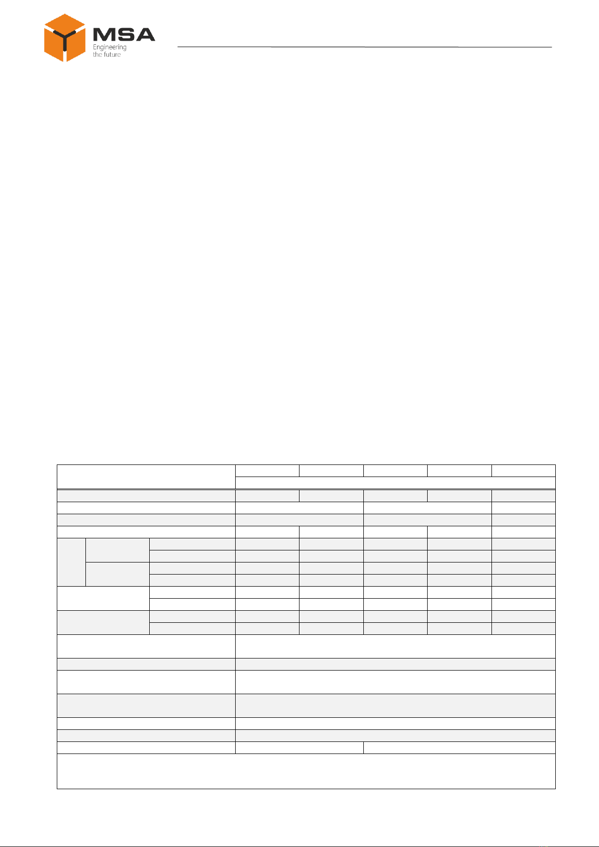
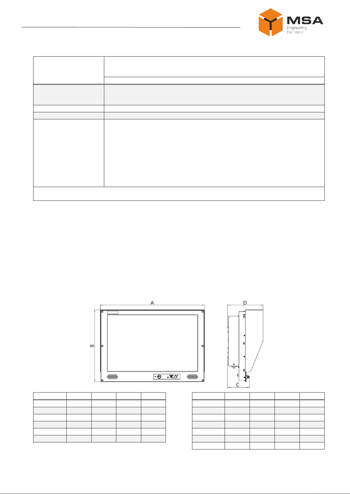
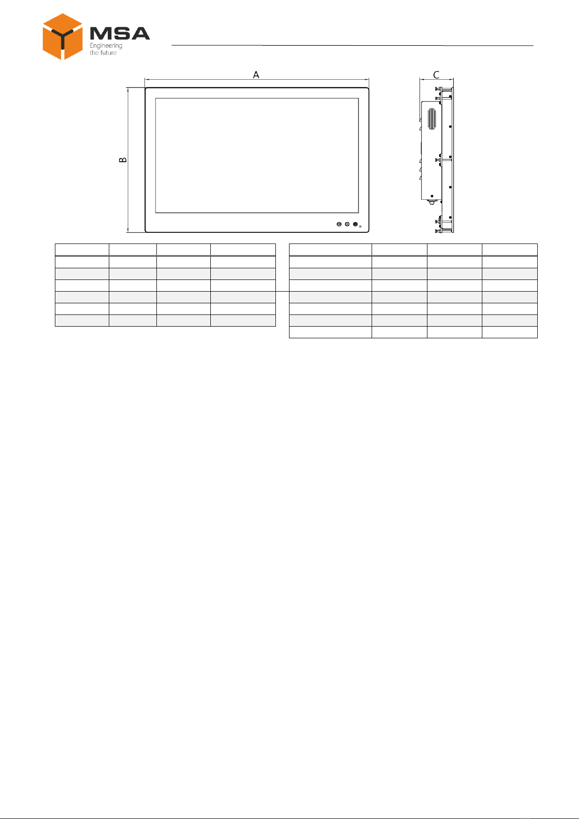
1.2 Technical specifications..........................................................................................................4
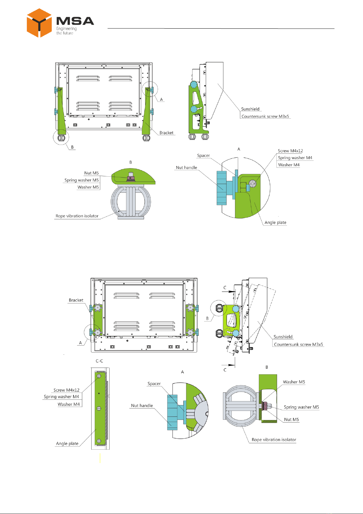
1.3 Structure and operation...........................................................................................................9
1.4 Measurement tools, instruments and appliances...................................................................19
1.5 Marking and sealing..............................................................................................................19
1.6 Packaging..............................................................................................................................19
2INTENDED USE...................................................................................................................20
2.1 Operational limitations..........................................................................................................20
2.2 Preparation for the Product operation...................................................................................20
2.3 Usage of the Product.............................................................................................................21
3TECHNICAL SERVICE OF THE PRODUCT.................................................................22
3.1 General instructions ..............................................................................................................22
3.2 Safety features.......................................................................................................................22
3.3 Maintenance routine..............................................................................................................22
3.4 Preservation...........................................................................................................................23
4CURRENT REPAIR OF THE PRODUCT........................................................................24
4.1 General instructions ..............................................................................................................24
4.2 Safety features.......................................................................................................................24
4.3 Сurrent repair........................................................................................................................24
5STORAGE.............................................................................................................................25
6TRANSPORTATION...........................................................................................................26
7DISPOSAL.............................................................................................................................27
8WARRANTY.........................................................................................................................28

3 Version 1.0
Marine computer monoblock
MVPC-хх04, MVPC-хх05, MVPC-хх06, MVPC-хх07
INTRODUCTION
This operating manual (hereinafter referred to as the OM) covers structure, con-
struction, specifications of Marine computer monoblock type MVPC-хх04, MVPC-хх05,
MVPC-хх06, MVPC-хх07 (hereinafter referred to as the Product), its components and
instructions required for the Product’s correct and safe operation (intended use, technical
service, current repair), as well as disposal information for its components.
Only those who have read operational documentation shall be permitted to oper-
ate with the Product.
Only those who have had general education in the area of electronic devices and
read operational documentation shall be permitted to provide the Product’s service.
Terms and abbreviations:
CL –check list;
OM –operating manual;
ТS –technical service;
TS-1 –semi-annual technical service;
TS-2 –annual technical service.

Version 1.0 4
Operating Manual
MVPC-хх04, MVPC-хх05, MVPC-хх06, MVPC-хх07
1DESCRIPTION AND OPERATION OF THE PRODUCT
1.1 DESCRIPTION
The Product is designed to be applied as a control computer, component of
shipborne automation, navigation and surveillance devices, etc., and to indicate textu-
al, graphic and other data types.
1.2 TECHNICAL SPECIFICATIONS
1.2.1 The Product ensures:
‒control, conversion (transformation), reception and transmission of data by
the connected input/output interfaces according to the connected ports;
‒automated data processing in accordance with the installed software;
‒displaying computing processes in accordance with the installed software;
‒backlight dimming from the front panel;
‒operation with the mains 50 Hz to 60 Hz, rated voltage 110, 220 V AC
or 12, 24 V DC.
The Product can be optionally applied as a data input device using capacitive
touch panel.
1.2.2 Main parameters and technical specifications of the Product
are represented in tables 1–6.
Table 1 –Technical specifications of the MVPC-хх04
Parameter
MVPC-1204
MVPC-1504
MVPC-1704
MVPC-1904
MVPC-2104
Value
Screen diagonal *
12.1"
15"
17"
19"
21.3"
Screen format
4:3
5:4
4:3
Screen resolution
1024х768
1280х1024
1600х1200
Viewable area, mm
245х184
304х228
337х270
376х301
432х324
Viewing
angle
vertical
standard brightness
80°/80°
70°/80°
80°/80°
89°/89°
89°/89°
high brightness
80°/80°
70°/80°
70°/70°
89°/89°
89°/89°
horizontal
standard brightness
80°/80°
80°/80°
85°/85°
89°/89°
89°/89°
high brightness
80°/80°
80°/80°
80°/80°
89°/89°
89°/89°
Contrast ratio
standard brightness
700:1
800:1
1000:1
1000:1
1800:1
high brightness
800:1
800:1
700:1
1000:1
1800:1
Brightness, cd/m² ***
standard
500
450
350
300
1000:1
high
1000
1600
800
700
1000:1
Screen surface
anti-glare glass;
anti-glare touch screen
Supply voltage **
220 VAC, 110 VAC, 24 VDC, 12 VDC
Protection degree
IP22;
IP56 - front side, IP22 - other surfaces
Type of connectors (one of available op-
tions)
standard;
protected
Operating temperature, °С
–15 to +55
Temperature limit, °С
–60 to +70
Dynamics
no
yes
*The monoblocks may be delivered with non-standard diagonals.
** One of available options.
*** Brightness may differ depending on a particular order.

5 Version 1.0
Marine computer monoblock
MVPC-хх04, MVPC-хх05, MVPC-хх06, MVPC-хх07
Table 2 –Technical specifications of the MVPC-хх05
Parameter
MVPC-
1005
MVPC-
2105
MVPC-
2305
MVPC-
2405
MVPC-
2705
MVPC-
3205
MVPC-
4205
MVPC-
4605
Value
Screen diagonal *
10.1"
21.5"
23"
24.1"
27"
31.5"
42"
46"
Screen format
16:10
16:9
16:10
16:9
Screen resolution
1280х800
1920х1080
1920х1200
1920х1080
Viewable area, mm
217х136
476х268
509х286
518х324
597х336
698х392
930х523
1018х572
Viewing angle
vert
ical
standard brightness
85°/85°
89°/89°
high brightness
hor
izo
ntal
standard brightness
85°/85°
89°/89°
high brightness
Contrast ratio
standard
brightness
1300:1
5000:1
1000:1
1000:1
1000:1
3000:1
4000:1
4000:1
high bright-
ness
1300:1
3000:1
1000:1
1000:1
1000:1
4000:1
4000:1
4000:1
Brightness,
cd/m² ***
standard
360
300
300
300
300
500
500
700
high
360
700
300
1200
1000
1000
700
1500
Screen surface
touch
screen
anti-glare glass;
anti-glare touch screen
Supply voltage **
220 VAC, 110 VAC, 24 VDC, 12 VDC
220 VAC, 110 VAC, 24 VDC
Protection degree
IP22;
IP56 - front side, IP22 - other surfaces
Type of connectors (one of
available options)
standard;
protected
Operating temperature, °С
–15 to +55
Temperature limit, °С
–60 to +70
Dynamics
no
yes
*The monoblocks may be delivered with non-standard diagonals.
** One of available options.
*** Brightness may differ depending on a particular order.
Table 3 –Technical specifications of the MVPC-хх06
Parameter
MVPC-1206
MVPC-1506
MVPC-1706
MVPC-1906
MVPC-2106
Value
Screen diagonal *
12.1"
15"
17"
19"
21.3"
Screen format
4:3
5:4
4:3
Screen resolution
1024х768
1280х1024
1600х1200
Viewable area, mm
246х184
304х228
337х270
376х301
432х324
Viewing
angle
vertical
standard brightness
80°/80°
70°/80°
80°/80°
89°/89°
89°/89°
high brightness
80°/80°
70°/80°
70°/70°
89°/89°
89°/89°
hori-
zontal
standard brightness
80°/80°
80°/80°
85°/85°
89°/89°
89°/89°
high brightness
80°/80°
80°/80°
80°/80°
89°/89°
89°/89°
Contrast ratio
standard brightness
700:1
800:1
1000:1
1000:1
1800:1
high brightness
800:1
800:1
700:1
1000:1
1800:1
Brightness,
cd/m² ***
standard
500
450
350
300
1000
high
1000
1600
800
700
1000
Screen surface
anti-glare glass;
anti-glare touch screen
Supply voltage **
220 VAC, 110 VAC, 24 VDC, 12 VDC
Protection degree
IP22;
IP56 - front side, IP22 - other surfaces
Type of connectors (one out of
available options)
standard;
protected
Operating temperature, °С
–15 to +55
Temperature limit, °С
–60 to +70
Dynamics
no
yes
*The monoblocks may be delivered with non-standard diagonals.
** One of available options.
*** Brightness may differ depending on a particular order.

Version 1.0 6
Operating Manual
MVPC-хх04, MVPC-хх05, MVPC-хх06, MVPC-хх07
Table 4 –Technical specifications of the MVPC-хх07
Parameter
MVPC-
1007
MVPC-
2107
MVPC-
2307
MVPC-
2407
MVPC-
2707
MVPC-
3207
MVPC-
4207
MVPC-
4607
Value
Screen diagonal *
10.1"
21.5"
23"
24.1"
27"
31.5"
42"
46"
Screen format
16:10
16:9
16:10
16:9
Screen resolution
1280х800
1920х1080
1920х1200
1920х1080
Viewable area, mm
217х136
476х268
509х286
518х324
597х336
698х392
930х523
1018х572
Viewing angle
vertical
standard
brightness
85°/85°
89°/89°
high brightness
hori-
zontal
standard
brightness
85°/85°
89°/89°
high brightness
Contrast
ratio
standard brightness
1300:1
5000:1
1000:1
1000:1
1000:1
3000:1
4000:1
4000:1
high brightness
1300:1
3000:1
1000:1
1000:1
1000:1
4000:1
4000:1
4000:1
Brightness
, cd/m² ***
standard
360
300
300
300
300
500
500
700
high
360
700
300
1200
1000
1000
700
1500
Screen surface
touch
screen
anti-glare glass;
anti-glare touch screen
Supply voltage **
220 VAC, 110 VAC, 24 VDC, 12 VDC
220 VAC, 110 VAC, 24 VDC
Protection degree
IP22;
IP56 - front side, IP22 - other surfaces
Type of connectors (one out
of available options)
standard;
protected
Operating temperature, °С
–15 to +55
Temperature limit, °С
–60 to +70
Dynamics
no
yes
*The monoblocks may be delivered with non-standard diagonals.
** One of available options.
*** Brightness may differ depending on a particular order.
Table 5 –Technical specifications of products with screen diagonal 10"–17"
Parameter
MVPC-1005, MVPC-1204,
MVPC-1007, MVPC-1206
MVPC-1504, MVPC-1704,
MVPC-1506, MVPC-1706
Value
CPU
Intel Celeron N3350, 2 cores 1.1 GHz
RAM
DDR3L, 8 GB
Type and capacity of HDD
SSD, 120 GB to 1 TB
Supported
interfaces
Ethernet 10/100/1000 Base-T - 1 pc.
(2 pcs. at option)
USB 3.0 - 2 pcs. on the rear panel
USB 2.0 - 1 pc. on the front panel**
COM (RS-232/422) - 2 pcs.
Audio (output, microphone) - 1 pc.
HDMI - 1 pc.
Ethernet 10/100/1000 Base-T - 1 pc.
(2 pcs. at option)
USB 3.0 - 2 pcs. on the rear panel
USB 2.0 - 1 pc. on the front panel*
COM (RS-232/422) - 4 pcs.
Audio (output, microphone) - 1 pc.
HDMI - 1 pc.
*Number and type of interfaces may differ from the ones specified.
** Only for MVPC-хх04, MVPC-хх05.

7 Version 1.0
Marine computer monoblock
MVPC-хх04, MVPC-хх05, MVPC-хх06, MVPC-хх07
Table 6 –Technical specifications of products with screen diagonal 19"–46"
Parameter
MVPC-1904, MVPC-2104, MVPC-2105, MVPC-2305, MVPC-2405, MVPC-2705,
MVPC-3205, MVPC-4205, MVPC-4605, MVPC-1906, MVPC-2106, MVPC-2107,
MVPC-2307, MVPC-2407, MVPC-2707, MVPC-3207, MVPC-4207, MVPC-4607
Value
CPU
Intel Core i7- 9700, 8 cores 3 GHz
Intel Core i5-8500, 6 cores 3 GHz
Intel Core i3-9100, 4 cores 3.6 GHz
RAM
DDR4 SO-DIMM, 8 to 32 GB
Type and capacity of HDD
SSD, 120 GB to 4 TB
Supported
interfaces
USB 3.0 - 2 pcs.on the rear panel
USB 2.0 - 2 pcs. on the rear panel
USB 2.0 - 1 pc. * on the front panel
Ethernet 10/100/1000 Base-T - 2 pcs.
Audio input, audio output, microphone - 1 pc.
HDMI - 1 pc. (VGA - 1 pc. at option)
COM (RS-232/422/485) - 4 pcs. **
DisplayPort - 1 pc.
Mini DisplayPort - 1 pc.
SATA - 1 pc.
*Only for MVPC-хх04, MVPC-хх05,
** 4 pcs. for MVPC-хх06, MVPC-хх07 type.
1.2.3 Products’ overall dimensions depending on the diagonal are represented in
figures 1 and 2.
Notes
1 Figures 1 and 2 show overall dimensions of the Products’ casings not includ-
ing a set of mounting brackets.
2 Overall dimensions in figures 1 and 2 are informative and may differ from
particular Product design depending on the order. Contact the Manufacturer to receive
overall dimensions for a particular Product type.
Type
А, mm
B, mm
C, mm
D, mm
Type
А, mm
B, mm
C, mm
D, mm
MVPC-1005
266.5
230
121.5
177
MVPC-2105
552
360
125.5
205
MVPC-1204
325
263
118
177
MVPC-2305
590
377
120
198.5
MVPC-1504
384.5
314
121.5
201
MVPC-2405
602
417
125.5
205
MVPC-1704
417.5
360
123.5
203
MVPC-2705
674
424
118
207.5
MVPC-1904
415,3
388
121
200.5
MVPC-3205
811
542
128.5
218
MVPC-2104
514.5
413
127
206.5
MVPC-4205
1051
675
130
269.5
MVPC-4605
1144.5
727.5
129
268.5
Figure 1 –Overall dimensions of the Products MVPC-хх04, MVPC-ХХ05 type

Version 1.0 8
Operating Manual
MVPC-хх04, MVPC-хх05, MVPC-хх06, MVPC-хх07
Type
А, mm
B, mm
C, mm
Type
А, mm
B, mm
C, mm
MVPC-1007
260
198
102.5
MVPC-2107
529.5
347.5
93.5
MVPC-1206
302.5
251
100
MVPC-2307
567.5
364.5
102
MVPC-1506
362
302
103
MVPC-2407
590
419.5
108.5
MVPC-1706
395
348
105.5
MVPC-2707
662
426.5
100
MVPC-1906
430.5
375.5
103
MVPC-3207
759
478
102
MVPC-2106
492
401
109
MVPC-4207
1000
611
112
MVPC-4607
1092.5
663.5
112
Figure 2 –Overall dimensions of the Products MVPC-хх06, MVPC-xx07 type

9 Version 1.0
Marine computer monoblock
MVPC-хх04, MVPC-хх05, MVPC-хх06, MVPC-хх07
1.3 STRUCTURE AND OPERATION
1.3.1 Installation
The Product may have various types of mounting depending on a particular order.
For all types of mounting a sunshield is mounted using screws delivered in the mounting
kit. For desk-top or wall mounting of the Products with the diagonal more than 21" vibra-
tion isolators are provided. Types of mounting are shown in figures 3 − 7.
Caution! While mounting, provide 160 mm free space from the detachable con-
nection to connect the Product.
1)Panel mounting with outside fasteners (see figure 3) ensures fastening from
the front panel using mounting kit of metal ware.
Figure 3 –Panel mounting with outside fasteners
2)Panel mounting with inside fasteners (see figure 4) ensures fastening from the
inner panel of console using plates and a mounting kit of metal ware.
Figure 4 –Panel mounting with inside fasteners

Version 1.0 10
Operating Manual
MVPC-хх04, MVPC-хх05, MVPC-хх06, MVPC-хх07
3)Desk-top mounting with an adjustable bracket (see figure 5) ensures mounting
on a surface using adjustable brackets, nut handles and a mounting kit of metal ware.
Figure 5 –Desk-top mounting with an adjustable bracket
4)Wall mounting with an adjustable bracket (see figure 6) ensures mounting on
a surface using adjustable brackets, nut handles and a mounting kit of metal ware.
Figure 6 –Wall mounting with an adjustable bracket

11 Version 1.0
Marine computer monoblock
MVPC-хх04, MVPC-хх05, MVPC-хх06, MVPC-хх07
5) Wall mounting with a non-adjustable bracket (see figure 7) ensures mounting
on a surface using brackets and a mounting kit of metal ware.
Figure 7 –Wall mounting
1.3.2 General description
The Product is manufactured in metal casing, where a power connector, audio
ports, video ports, peripheral interfaces, local network ports are generally located. Con-
nectors are standard, see figure 8 (Layout of the Product's connectors may vary from the
specified ones).
For the description of connectors, see table 7. Electrical connectors pinouts are rep-
resented in tables 8–18.

Version 1.0 12
Operating Manual
MVPC-хх04, MVPC-хх05, MVPC-хх06, MVPC-хх07
The Products with diagonals 10" - 12"
The Products with diagonals 15" - 17"
The Products with diagonals 19" - 46"
Figure 8 –Connectors layout depending on the diagonal
Table 7 –Description of the Product’s connectors
N.
Name
Description
Type
1
XPn.8
To connect AC voltage 220 V, 50 Hz
C13
XPn.9
To connect AC voltage 110 V, 50 Hz
C13
2
XSn.10
To connect DC voltage 24 V
C14
XSn.11
To connect DC voltage 12 V
C14
3
XSn.1
To connect VGA
DB-15F
4
XSn.4
To connect HDMI
HDMI
5
XPn.15
To connect common audio
РС10ТВ
6
XSn.12
To connect audio input
3.5 jack
XSn.13
To connect audio output (speaker)
3.5 jack
XSn.14
To connect microphone
3.5 jack

13 Version 1.0
Marine computer monoblock
MVPC-хх04, MVPC-хх05, MVPC-хх06, MVPC-хх07
N.
Name
Description
Type
7
XSn.17
To connect Ethernet 10/100/1000 Base-T
RJ-45
8
XPn.24
To connect universal serial interface COM (RS-232/422/485)
DB-9M
9
XPn.31
To connect universal serial interface COM (RS-232/422)
DB-9M
10
XSn.25
To connect USB devices
USB type A
11
XSn.5
To connect Display Port
Display Port
12
XSn.50
To connect Mini Display Port
Mini Display Port
13
XSn.47
External recycle bin connection for SSD
SATA
Note –“n”–ordinal number of same-type connectors. For example, if the device has 2 USB interfaces, they
are marked as: XS1.25, XS2.25.
Table 8 –Description of XSn.25 connector pins
Type
Pin №
Description
(view from connection side)
1
+ 5 V (VCC)
2
data –(D –)
3
data + (D +)
4
GND
USB 3.0
(view from connection side)
1
VCC
2
D–
3
D+
4
GND
5
TX–
6
TX+
7
GND_DRAIN
8
RX–
9
RX+
Table 9 –Description of XSn.1 connector pins
Type
Pin №
Description
1
2
3
4
5
6
7
8
9
10
11
12
13
14
15
(pinout of unit from side of
cable connection)
1
Red
2
Green
3
Blue
4
Not used
5
Common (GND)
6
GND_Red
7
GND_Green
8
GND_Blue
9
+ 5 В
10
GND
11
GND
12
data (SDA)
13
HSYNC
14
VSYNC
15
Data synch (SCL)

Version 1.0 14
Operating Manual
MVPC-хх04, MVPC-хх05, MVPC-хх06, MVPC-хх07
Table 10 –Description of XSn.4 connector pins
Type
Pin №
Description
(pinout of unit from side of ca-
ble connection)
1
TMDS 2 +
2
TMDS 2 Sh
3
TMDS 2 ˗
4
TMDS 1 +
5
TMDS 1 Sh
6
TMDS 1 ˗
7
TMDS 0 +
8
TMDS 0 Sh
9
TMDS 0 ˗
10
TMDS Cl +
11
TMDS Cl Sh
12
TMDS Cl ˗
13
CEC
14
Not used
15
SCL
16
SDA
17
GND
18
+ 5 V
19
HPD
Table 11 –Description of XSn.12, XSn.13, XSn.14 connectors pins
Type
Pin №
XSn.12, XSn.13
XSn.14
Description
1
GND
GND
2
LINE_R
MIC_VCC
3
LINE_L
MIC_IN
Table 12 –Description of XPn.15 connector pins
Type
Pin №
Description
(view from soldering side)
1
Common (GND)
2
Lin. right (Line_R)
3
Lin.left (Line_L)
4
common (GND)
5
In. micr. (Mic_In)
6
Micr.power (Mic_VCC)
7
Common (GND)
8
Aud.out.right (EAR_R)
9
Aud.out.left (EAR_L)
10
display
Table 13 –Description of XPn.24, XPn.31 connectors pins
Type
Pin №
Description
Application
RS-232
RS-422
RS-485
5 4 3 2 1
9876
(view from soldering side)
1
Rx +
‒
+
–
2
RxD
+
‒
‒
3
TxD
+
‒
‒
4
Tx +
‒
+
+
5
GND
+
+
–
6
Rx –
‒
+
–
7
RTS
+
‒
‒
8
CTS
+
‒
‒
9
Tx –
‒
+
+
10
Screen
+
+
+

15 Version 1.0
Marine computer monoblock
MVPC-хх04, MVPC-хх05, MVPC-хх06, MVPC-хх07
Table 14 –Description of XPn.8, XPn.9 connector pins
Type
Pin №
Description
1 2
(view from soldering side)
1
L
E (PE)
2
N
Table 15 –Description of XSn.10, XSn.11 connector pins
Type
Pin №
Description
12
(view from soldering side)
E (PE)
1
+ 24 V
2
0 V
Table 16 –Description of XSn.17 connector pins
Type
Pin №
Description
(view from connection side)
1
MDI 0 + (white orange)
2
MDI 0 ‒ (orange)
3
MDI 1 + (white green)
4
MDI 2 + (blue)
5
MDI 2 ‒ (white blue)
6
MDI 1 ‒ (green)
7
MDI 3 + (white brown)
8
MDI 3 ‒ (brown)
Table 17 –Description of XSn.5, XSn.50 connector pins
Type
Pin №
Description
Display Port
mini
Display Port
(pinout of unit from side
of cable connection)
(pinout of unit from
side of cable connec-
tion)
1
3
Main Link Lane 0+
2
1
GND (Земля)
3
5
Main Link Lane 0‒
4
9
Main Link Lane 1+
5
7
GND (Земля)
6
11
Main Link Lane 1‒
7
15
Main Link Lane 2+
8
8
GND (Земля)
9
17
Main Link Lane 2‒
10
10
Main Link Lane 3+
11
13
GND (Земля)
12
12
Main Link Lane 3‒
13
4
Configuration 1
14
6
Configuration 2
15
16
Auxiliary Channel+
16
14
GND
17
18
Auxiliary Channel‒
18
2
Hot Plug Detect
19
19
Return
20
20
DP_PWR

Version 1.0 16
Operating Manual
MVPC-хх04, MVPC-хх05, MVPC-хх06, MVPC-хх07
Table 18 –Description of XSn.47 connector pins
Type
Pin №
Description
(pinout of unit from side
of cable connection)
1
GND (Earth)
2
A+ (Data transmission)
3
A− (Data transmission)
4
GND (Earth)
5
B− (Data transmission)
6
B+ (Data transmission)
7
GND (Earth)
8
+3,3 В (Power)
9
+3,3 В (Power)
10
+3,3 В (Power)
11
GND (Earth)
12
GND (Earth)
13
GND (Earth)
14
+5 В (Power)
15
+5 В (Power)
16
+5 В (Power)
17
GND (Earth)
18
GND (Earth)
19
GND (Earth)
20
+12 В (Power)
21
+12 В (Power)
22
+12 В (Power)
1.3.3 Controls and indication of MVPC-хх04, MVPC-хх05 type
Colour display with a diagonal in compliance with tables 1 and 2 is located on
the front panel of the Products MVPC-хх04, MVPC-х05 type. The Product may be de-
livered in two types: anti-glare glass or touch capacitive panel.
Controls, indication (LEDs) and speakers are also located on the front panel, see
figure 9 (the Product’s appearance may be different and depends on order). Description
of the controls and indication (LEDs) are represented in table 19.

17 Version 1.0
Marine computer monoblock
MVPC-хх04, MVPC-хх05, MVPC-хх06, MVPC-хх07
Figure 9 –Layout of controls, indication (LEDs) and speakers on the front panel of
the Products MVPC-хх04, MVPC-хх05 type
Table 19 –Description of the controls and indication (LEDs)
N
Name
Description
1
Reset button
Button restarts the product.
2
Power button
Button switches on/off the product.
3
Display brightness
LED
LED shows display brightness status.
4
Brightness adjust-
ment knob (dimmer)
Knob ensures screen backlight adjustment.
5
USB
Provides connection of external USB devices
6
---
Speakers
7
---
Control and indication (LEDs) panel

Version 1.0 18
Operating Manual
MVPC-хх04, MVPC-хх05, MVPC-хх06, MVPC-хх07
1.3.4 Controls and indication (LEDs) of the Products MVPC-хх06,
MVPC-хх07 type
Colour display with a diagonal in compliance with tables 3 and 4 is located on
the front panel of the Products MVPC-хх06, MVPC-х07 type. The Product may be de-
livered in two types: anti-glare glass or touch capacitive panel.
Touch buttons with blue backlight are also located on the front panel, see
figure 10 (the Product’s appearance may be different and depends on order). Speakers, if
any available, are located on the back panel of the Product. Description of the controls
and indication (LEDs) see in table 18.
Figure 10 –Controls and indication (LEDs) layout on the front panel of
MVPC-хх06, MVPC-хх07
Table 20 –Description of controls and indication (LEDs)
Name
Description
Brightness adjustment buttons
Product on/off button with screen brightness indicator

19 Version 1.0
Marine computer monoblock
MVPC-хх04, MVPC-хх05, MVPC-хх06, MVPC-хх07
1.4 MEASUREMENT TOOLS,INSTRUMENTS AND APPLIANCES
Technical service (hereinafter −the TS) of the Product is carried out using tools
and consumables represented in table 21.
Table 21 –Number of consumables required for the TS
Name and identifier of consumables
Weight of consumables
Note
Cleaning cloth
0.10 kg
1To clean surfaces and parts of
the product –use clean cloth
2To clean severe contamina-
tion –use alcohol-soaked cloth
Rectified hydrolytic technical ethyl al-
cohol
0.05 l
To soak cloth while removing
contamination
Varnish
0.05 kg
To cover surfaces of the product
in case of paint coating damage
Abrasive cloth
0.06 х 0.06 m
To polish surfaces of the product
in case of paint coating damage
1.5 MARKING AND SEALING
The Product has a marking tag for connectors and nameplate where a user can
find a serial number, date of manufacturing, weight, protection degree, rated input volt-
age and power consumption.
1.6 PACKAGING
The Products are packed in a corrugated board box and inner packaging ensuring
its transportation and storage at the warehouse.
Transport packaging is also used as a returnable packaging for transportation of
the Product to the repair location and back. Packaging sealing is not provided.

Version 1.0 20
Operating Manual
MVPC-хх04, MVPC-хх05, MVPC-хх06, MVPC-хх07
2INTENDED USE
2.1 OPERATIONAL LIMITATIONS
The Product's installation place must be selected according to the operational
constraints (operating temperature and protection degree).
Caution! Installation site of the Product must not be less than 1 m from a magnetic
compass!
2.2 PREPARATION FOR THE PRODUCT OPERATION
2.2.1 Safety features
While preparing the Product for operation, check it visually after unpacking;
mechanical damage shall be absent.
Connection of the Product to the power mains must be provided only consider-
ing input power requirements.
The Products must be switched off and grounded before connection.
The staff shall follow “The technical rules for operation of electric installation”
and “Safety rules for operation of electric installation” while testing electrical circuits
and insulation resistance.
2.2.2 Method of the visual check
Before switching the Product on, the staff shall:
–observe visually the cable integrity and initial position of the controls on the
front panel;
–clean front panels from dust and dirt by clean soft cloth, if necessary;
–check reliable cable connections to the products and proper grounding.
2.2.3 Switching on instructions
While connecting the Product and preparing it for operation follow the steps be-
low:
make sure that power mains voltage conforms with input voltage require-
ments;
transfer circuit breakers of main power switchboard to “OFF”position;
connect power cable and interface cables to the Product;
transfer circuit breakers of main power switchboard to “ON” position;
press “Power”button on the front panel;
This manual suits for next models
29
Table of contents
Other MSA Marine Equipment manuals