Citadel AF300 PRO User manual

AF300 PRO INSTALLATION INSTRUCTIONS
SAFETY
Exercise caution when working on the vessel, especially in conned spaces or
when working near the bottom or “bilge” area of the boat.
Make sure the work area is properly ventilated prior to beginning installation.
These areas may contain residual fuel or fumes that can be harmful when inhaled.
Extreme vigilance should be used in these spaces especially when working alone.
A basic understanding of drilling, sanding and the vessel’s electrical system are needed for
the installation work required.
The equipment must be installed in accordance with these instructions.
Failure to do so could result in poor product performance, personal injury and/or damage to the vessel.
The success and performance of the system depends on a quality installation.
CLEANING OF THE HULL
It is important to clean the hull close to the time of the installation.
Barnacles and mussels, are not killed by this system.
This system kills the micro-organisms at the bottom of the food chain.
Algae and other vegetation are killed and consequently the barnacles & mussels that feed on them
will not attach to the hull.
ITEMS SUPPLIED
Included in this box:
Control Box Unit AF301C
Transducers from 1 to 4 AF301T as ordered
Transducer cables 1 RG6 coaxial cable for each transducer ordered 5m or10m
Two cable glands 12mm
One pack Devcon adhesive
! 1
Ultrasonic
Marine

Options if ordered:
AC shore power supply LPF60-30
INSTALLATION
Planning & Positioning
Before beginning work it is important to plan out the installation, taking note of:
The vessels hull design.
Location for the transducers and control box.
Cable runs and power supply.
Location of Control Box
The control box is sealed and water resistant so can be installed in the most convenient location, preferably
above the water line.
The length of cables to the transducers should be taken into consideration for the location of the control box.
Hull Construction
Ultrasonic sound waves will only work properly on breglass, aluminium and steel hulls.
The system is not suitable for wooden hulls.
Hull Mounting
Transducers must be bonded directly to the hull of the boat. Special care must be taken to ensure that they
are not bonded to a false oor, cavity, over a keel, or on the inner layer of a balsa/foam cored boat.
A direct connection to the hull may require removing any spacing or other layer such as a sandwich foam or
balsa core.
If working with steel or aluminium, be sure not to connect over welds or seams in the material.
Obstructions
Avoid mounting transducers close to any objects such as stringers, bulkheads, water tanks, fuel tanks,
transoms, depth nder and sh nder.
Ideally, they should be 30 cms away from these areas for the system to operate most effectively.
.
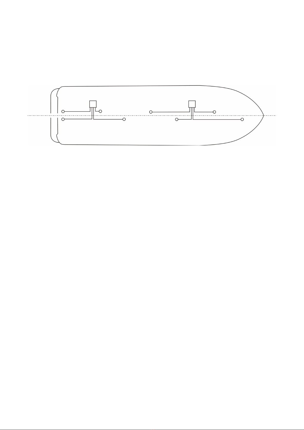
Transducer Positioning
The diagrams below show the general optimum areas for mounting transducers, since every vessel is
different. The illustration should be used as a general guide only.
On smaller power craft under 10m, the transducer should be positioned in the close proximity of the propeller
and shaft to help protect these isolated parts.
Transducers should be tted onto a solid part of the hull, see under hull mounting above.
They should also be approximately 30cms off the centre line.
For stern drive units, transducers should also be approximately 10 to 13cms forward of the transom.
These measurements are a guide only, but the surrounding structures in the vessel will determine the nal
position.
! 2
A reasonably at area of the hull should be chosen for transducer locations and the surface should be well
prepared before mounting (see preparation and mounting instructions below).
Typical Position:
Installing the Control Box
The control box is splash proof to IP66 and can be installed in any convenient location, preferably
above the water line.
1. Unscrew the four screws on the cover of the control box. These screws will not un-screw
completely, as they are designed to stay with the cover. Remove the cover and place it aside.
2. The mounting screws are placed in the same holes as the cover screws.
Use four suitable screws to secure the control box.
3. Mark the location for the four corner mounting screws. Using a drill bit, drill the mounting
holes. Use caution to make sure that you are not drilling into the hull of the boat.
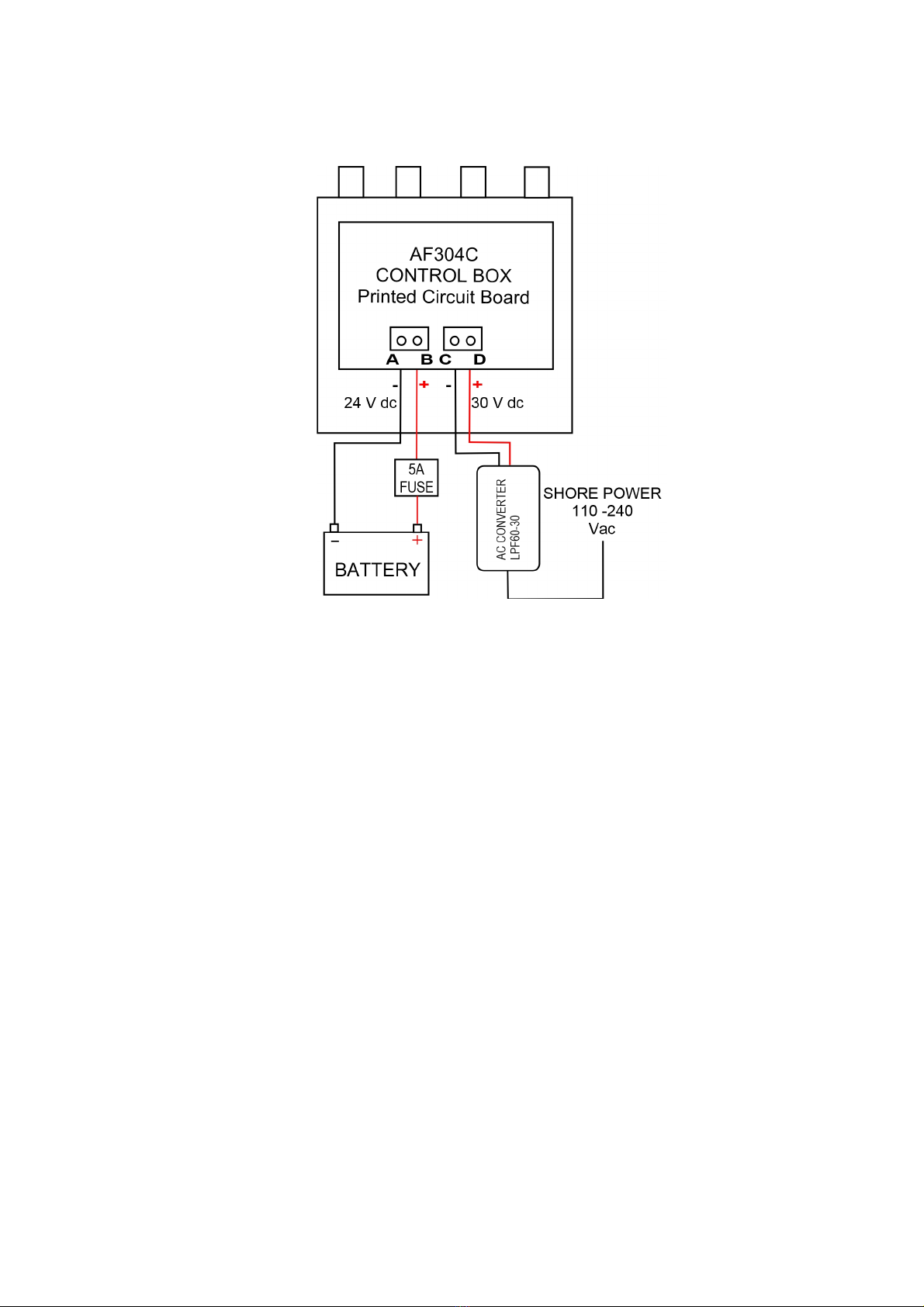
4. Locate the 24 volt DC power source. This can be either a protected circuit from vessels
electrical panel, or it can be direct to the battery via a local 5 amp fuse or circuit breaker.
Use stranded cable rated at 5 amps or more. Leave switched off until testing the installation.
5. Connect cable from terminal A, negative and B, positive via the supplied cable gland to a
suitable permanently on, protected 24 volt DC supply.
6. IMPORTANT! When using optional shore power, connections should be made to the
terminal block marked C, negative and D, positive.
When the optional AC shore power supply LPF60-30 converter is ordered,
power will automatically be taken from the shore supply and not the battery.
7. Replace the control box cover.
For operation from a solar panel, contact us for advice.
! 3
Mounting the Transducer to the Hull
When mounting transducers, the goal is to make 100% contact between the transducer and the
hull. The better you prepare the surface, the better the result.
To make a neat and tidy installation, proceed as follows:-
1. Degrease the general area where mounting the transducer and also degrease the face of
the transducer using either isopropyl alcohol, methylated or surgical spirit.
2. Draw a pencil circle around base of transducer as photograph number one below, abrade
hull within this circle using medium grade sandpaper. Mask around circle as in the
photograph two below. Also mask lower part of the transducer.
3. Following the Devcon instructions, install each transducer one at a time. Place transducer in
center of masked area and push down hard to expel surplus Devcon. Masking tape should
be used during bonding to keep the transducers in place on sloping parts of the hull. After
about three minutes, depending on temperature, run around perimeter of transducer with a
sharp pointed blade and ease surplus away.
4. Allow 1 hour for Devcon to set before removing the masking tape which should come away
with the surplus Devcon. Take care not to disturb transducer during the above process while
the Devcon sets.
! 4
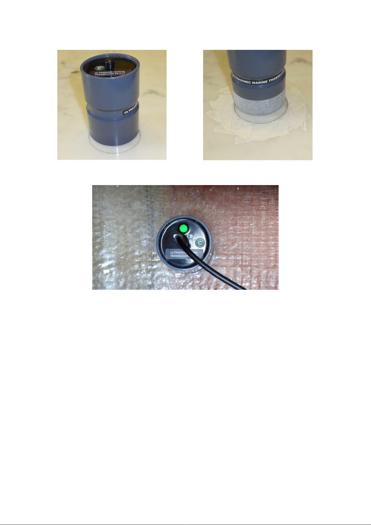
1 2
Installed transducer
Running the Transducer Cables
Having mounted the transducers and control box, the cables can now be connected to the units.
Up to four transducers can be connected to a single control box.
Maximum 30m cable length per transducer.
Testing and Operation
With the control box closed, connect and turn on the power supply.
Two status LEDs are viewable through the cover of the control box and indicate the following:
• Green ashing LED indicates correct operation of the control box.
• Red ashing LED indicated battery voltage is low and transducers switched off to save on battery
usage.
LED light on the transducers indicate the following:
• Green ashing indicates transducer is working.
! 5

Technical Support
If your system is not working and you are unable to resolve the problem,
Issue 2.6 December 2017
! 6
This manual suits for next models
2
Table of contents


