MSI MEG X670E ACE User manual

MEG X670E ACE
Motherboard
User Guide
Benutzerhandbuch
Manuel d’utilisation

1
Contents
Quick Start..................................................................................................................... 3
Specifications.............................................................................................................. 16
Special Features......................................................................................................... 21
Package Contents ...................................................................................................... 22
Back Panel Connectors ............................................................................................. 23
LAN Port LED Status Table .................................................................................. 25
Audio Jacks Connection ....................................................................................... 25
Installing Antennas............................................................................................... 27
Overview of Components........................................................................................... 28
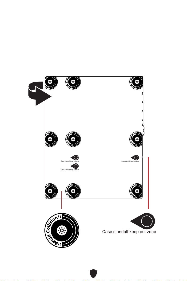
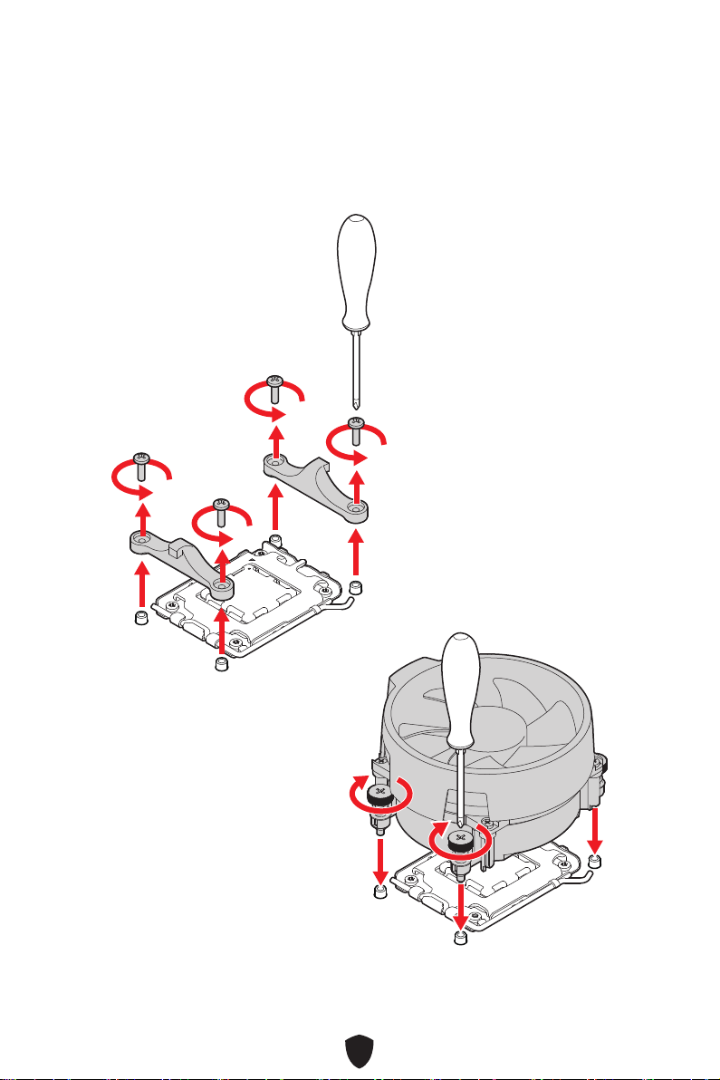
CPU Socket ........................................................................................................... 29
DIMM Slots............................................................................................................ 30
PCI_E1~3: PCIe Expansion Slots.......................................................................... 31
M2_1~4: M.2 Slots (Key M) ................................................................................... 33
Installing M.2 Xpander-Z Gen 5 Dual card........................................................... 40
SATA_P3~4, SATA_S3~4 & SATA_A1~2: SATA 6Gb/s Connectors ...................... 44
JAUD1: Front Audio Connector ............................................................................ 45
JFP1, JFP2: Front Panel Connectors................................................................... 45
CPU_PWR1~2, ATX_PWR1, PD_PWR1: Power Connectors ................................ 46
JCI1: Chassis Intrusion Connector....................................................................... 47
JUSB1: USB 3.2 Gen 2 10Gbps Type-C front panel Connector............................ 48
JUSB2: USB 3.2 Gen 2x2 20Gbps Type-C front panel Connector........................ 48
JUSB3~4: USB 3.2 Gen 1 Connectors .................................................................. 49
JUSB5~6: USB 2.0 Connectors............................................................................. 50
JTPM1: TPM Module Connector........................................................................... 50
JSLOW1: Slow Mode Booting Jumper.................................................................. 51
JLN1: Low Temperature Booting Jumper ........................................................... 51
W_FLOW1: Water Flow Meter Connector ............................................................ 52
T_SEN1~2: Thermal Sensor Connector............................................................... 52
JOCFS1: Safe Boot Jumper.................................................................................. 52
CPU_FAN1, PUMP_FAN1~2, SYS_FAN1~5: Fan Connectors.............................. 53
JBAT1: Clear CMOS (Reset BIOS) Jumper........................................................... 54
BAT1: CMOS Battery............................................................................................. 54
BIOS_SW1: Multi-BIOS Switch ............................................................................. 55
English

2
POWER1, RESET1: Power Button, Reset Button ................................................. 55
JRGB1: RGB LED connector................................................................................. 56
JARGB_V2_1~3: A-RAINBOW V2 (ARGB Gen2) LED connectors......................... 57
V-Check Points Lite .............................................................................................. 59
JDASH1 : Tuning Controller connector................................................................ 59
Onboard LEDs............................................................................................................. 60
EZ Debug LED....................................................................................................... 60
JPWRLED1: LED power input............................................................................... 60
LED_SW1: EZ LED Control................................................................................... 60
Debug Code LED................................................................................................... 61
Boot Phases.......................................................................................................... 61
Debug Code LED Table......................................................................................... 61
Installing OS, Drivers & MSI Center.......................................................................... 66
MSI Center............................................................................................................ 67
UEFI BIOS.................................................................................................................... 68
BIOS Setup............................................................................................................ 69
Resetting BIOS...................................................................................................... 70
Updating BIOS....................................................................................................... 70

3
Quick Start
Thank you for purchasing a new motherboard from MSI®. This Quick Start section
provides demonstration diagrams about how to install your computer. Some of the
installations also provide video demonstrations. Please link to the URL to watch it
with the web browser on your phone or tablet. You may have even link to the URL by
scanning the QR code.
Preparing Tools and Components
AMD® AM5 CPU
AM5 CPU Fan
DDR5 Memory
Graphics Card
SATA Hard Disk Drive
Phillips Screwdriver
Chassis
Power Supply Unit
A Package of Screws
Thermal Paste

4
Safety Information
The components included in this package are prone to damage from electrostatic
discharge (ESD). Please adhere to the following instructions to ensure successful
computer assembly.
Ensure that all components are securely connected. Loose connections may cause
the computer to not recognize a component or fail to start.
Hold the motherboard by the edges to avoid touching sensitive components.
It is recommended to wear an electrostatic discharge (ESD) wrist strap when
handling the motherboard to prevent electrostatic damage. If an ESD wrist strap
is not available, discharge yourself of static electricity by touching another metal
object before handling the motherboard.
Store the motherboard in an electrostatic shielding container or on an anti-static
pad whenever the motherboard is not installed.
Before turning on the computer, ensure that there are no loose screws or metal
components on the motherboard or anywhere within the computer case.
Do not boot the computer before installation is completed. This could cause
permanent damage to the components as well as injury to the user.
If you need help during any installation step, please consult a certified computer
technician.
Always turn off the power supply and unplug the power cord from the power outlet
before installing or removing any computer component.
Keep this user guide for future reference.
Keep this motherboard away from humidity.
Make sure that your electrical outlet provides the same voltage as is indicated on
the PSU, before connecting the PSU to the electrical outlet.
Place the power cord such a way that people can not step on it. Do not place
anything over the power cord.
All cautions and warnings on the motherboard should be noted.
If any of the following situations arises, get the motherboard checked by service
personnel:
• Liquid has penetrated into the computer.
• The motherboard has been exposed to moisture.
• The motherboard does not work well or you can not get it work according to user
guide.
• The motherboard has been dropped and damaged.
• The motherboard has obvious sign of breakage.
Do not leave this motherboard in an environment above 60°C (140°F), it may damage
the motherboard.

5
Case stand-off notification
To prevent damage to the motherboard, any unnecessary mounting stand-off between
the motherboard circuits and the computer case is prohibited. The Case standoff keep
out zone signs will be marked on the backside of motherboard (as shown below) to
serve as a warning to user.
Avoid collision notification
Protective paint is printed around each screw hole to prevent parts from being
scratched.

6
Installing a Processor
11
22
33
6644
55
77
88
1111
99
1010
https://youtu.be/cltgIYiGtWY

7
Important
If you are installing the screw-type CPU heatsink, please follow the figure below to
remove the retention module first and then install the heatsink.

8
Installing DDR5 memory
DIMMA2 DIMMA2
DIMMB2
DIMMA1
DIMMA2
DIMMB1
DIMMB2
https://youtu.be/XiNmkDNZcZk

9
HDD LED
RESET SW
Connecting the Front Panel Header
http://youtu.be/DPELIdVNZUI
JFP1
HDD LED HDD LED -
HDD LED +
POWER LED -
POWER LED +
POWER LED
RESET SW
POWER SW
POWER LED+
POWER LED-
HDD LED
1
2 10
9
Power LED
Reserved
Power Switch
JFP1
Reset SwitchHDD LED

10
Installing the Motherboard
11
https://youtu.be/wWI6Qt51Wnc
Torque:
3 kgf·cm*
*3 kgf·cm
= 0.3 N·m
= 2.6 lbf·in
22

11
Connecting the Power Connectors
http://youtu.be/gkDYyR_83I4
ATX_PWR1
CPU_PWR1~2
PD_PWR1

12
Installing SATA Drives
http://youtu.be/RZsMpqxythc
11
2233
44
55

13
Installing a Graphics Card
http://youtu.be/mG0GZpr9w_A
11
22
33
44
55
66

14
Connecting Peripheral Devices

15
Power On
44
33
1122

16
Specifications
CPU
Supports AMD Ryzen™ 7000 Series Desktop Processor*
Processor socket AM5
* Please go to www.msi.com to get the newest support status as new processors
are released.
Chipset AMD X670 Chipset
Memory
4x DDR5 memory slots, supporting up to 128GB*
Supports 1R 4800 MHz by JEDEC
Max. overclocking frequency:
• 1DPC 1R Max. speed up to 6666+ MHz
• 1DPC 2R Max. speed up to 6000+ MHz
• 2DPC 1R Max. speed up to 6400+ MHz
• 2DPC 2R Max. speed up to 4000+ MHz
Supports Dual-Channel mode
Supports non-ECC, un-buffered memory
Supports AMD EXPO
* Please refer to www.msi.com for more information on compatible memory.
Expansion Slots
3x PCIe x16 slots
• Supports x16/x0/x4, x8/x8/x4
• PCI_E1, PCI_E2 & PCI_E3 slots (From CPU)
• PCI_E1 supports up to PCIe 5.0 x16
• PCI_E2 supports up to PCIe 5.0 x8
• PCI_E3 supports up to PCIe 5.0 x4
Multi-GPU Supports AMD Multi-GPU
Onboard Graphics
1 x DisplayPort 1.4 over USB-C with HBR3 supports a
maximum resolution of 4K 120Hz*/**
*Available only on processors featuring integrated graphics.
** Graphics specifications may vary depending on the CPU installed.
SATA Ports
6x SATA 6Gb/s ports
• SATA_P3~P4 & SATA_S3~S4 (From X670 chipset)
• SATA_A1~A2 (From ASM1061)
Continued on next column

17
Continued from previous column
M.2 SSD Slots
4x M.2 slots (Key M)
• M2_1 slot (From CPU)
• Supports up to PCIe 5.0 x4
• Supports 2260/ 2280 storage devices
• M2_2 slot (From X670 chipset)
• Supports up to PCIe 4.0 x4
• Supports 2260/ 2280 storage devices
• M2_3 slot (From X670 chipset)
• Supports up to PCIe 4.0 x4
• Supports 2260/ 2280 storage devices
• M2_4 slot (From X670 chipset)
• Supports up to PCIe 4.0 x4
• Supports 2280/ 22110 storage devices
RAID
Supports RAID 0, RAID 1 and RAID 10 for SATA storage
devices*
Supports RAID 0, RAID 1 and RAID 10 for M.2 NVMe
storage devices
* SATA_A1~A2 do not support RAID function.
Audio
Realtek® ALC4082 Codec + ESS ES9280AQ Combo DAC/
HPA
• 7.1-Channel USB High Performance Audio
• Supports up to 32-bit/384kHz playback on front panel.
• Supports S/PDIF output
LAN 1x Marvell® AQC113CS-B1-C 10Gbps LAN controller
Continued on next column

18
Continued from previous column
Wi-Fi & Bluetooth®
AMD Wi-Fi 6E
The Wireless module is pre-installed in the M.2 (Key-E)
slot
Supports MU-MIMO TX/RX
Supports 20MHz, 40MHz, 80MHz,160MHz bandwidth in
2.4GHz/ 5GHz or 6GHz* bands
Supports 802.11 a/ b/ g/ n/ ac/ ax
Supports Bluetooth® 5.2**
* Wi-Fi 6E 6GHz may depend on every country’s regulations and will be ready in
Windows 10 build 21H1 and Windows 11.
** Bluetooth 5.2 will be ready in Windows 10 build 21H1 and Windows 11.
Power Connectors
1x 24-pin ATX main power connector
2x 8-pin +12V power connectors
1x 6-pin PCIe power connector*
* To achieve USB PD 60W fast charging, the PD_PWR1 connector needs to be
connected to the power supply unit.
Internal USB
Connectors
1x USB 3.2 Gen 2x2 20Gbps Type-C front panel connector*
(From X670 chipset)
• Supports USB PD 60W fast charging**
1x USB 3.2 Gen 2 10Gbps Type-C front panel connector
(From X670 chipset)
2x USB 3.2 Gen 1 5Gbps conencotrs (From ASM1074)
• Supports additional 4 USB 3.2 Gen 1 5Gbps ports
2x USB 2.0 connectors (From X670 chipset)
• Supports additional 4 USB 2.0 ports
* JUSB2 doesn’t support USB 2.0 device.
** To achieve USB PD 60W fast charging for JUSB2, the PD_PWR1 connector
needs to be connected to the power supply unit.
Fan Connectors
1x 4-pin CPU fan connector
2x 4-pin water-pump fan connectors
5x 4-pin system fan connectors
Continued on next column
Table of contents
Languages:
Other MSI Motherboard manuals

MSI
MSI MS-7275 User manual

MSI
MSI MPG Z590 GAMING CARBON WIFI User manual

MSI
MSI H310M PRO-M2 User manual

MSI
MSI 945PL Neo5 Series User manual

MSI
MSI X79A-GD45 Plus seres User manual

MSI
MSI MS-7360 User manual

MSI
MSI 649 Neo-V User manual

MSI
MSI MS-9896 User manual

MSI
MSI B550M PRO-VDH WIFI6 User manual

MSI
MSI MAG B460M MORTAR WIFI User manual

MSI
MSI Z68A-GD80 G3 series User manual

MSI
MSI MAG Z790 TOMAHAWK WIFI User manual

MSI
MSI AM1M Series User manual

MSI
MSI Super Q965 User manual

MSI
MSI P7N SLI-FI - Motherboard - ATX User manual

MSI
MSI MEG Z690 GODLIKE User manual

MSI
MSI P55-GD55 User manual

MSI
MSI MS-7236 User manual

MSI
MSI KT6 Delta-FIS2R User manual

MSI
MSI MD 5000 User manual