MSI Z390-S01 User manual

1
< 1> Contents
Contents
Safety Information...........................................................................................2
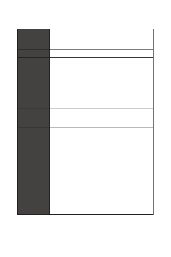
Specifications...................................................................................................3
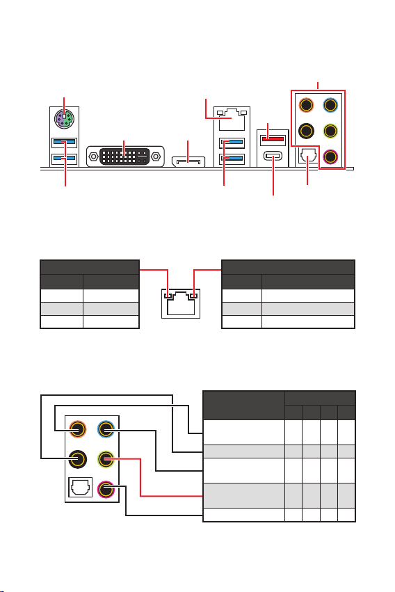
Rear I/O Panel ................................................................................................. 6
LAN Port LED Status Table.................................................................................6
Audio Ports Configuration ..................................................................................6
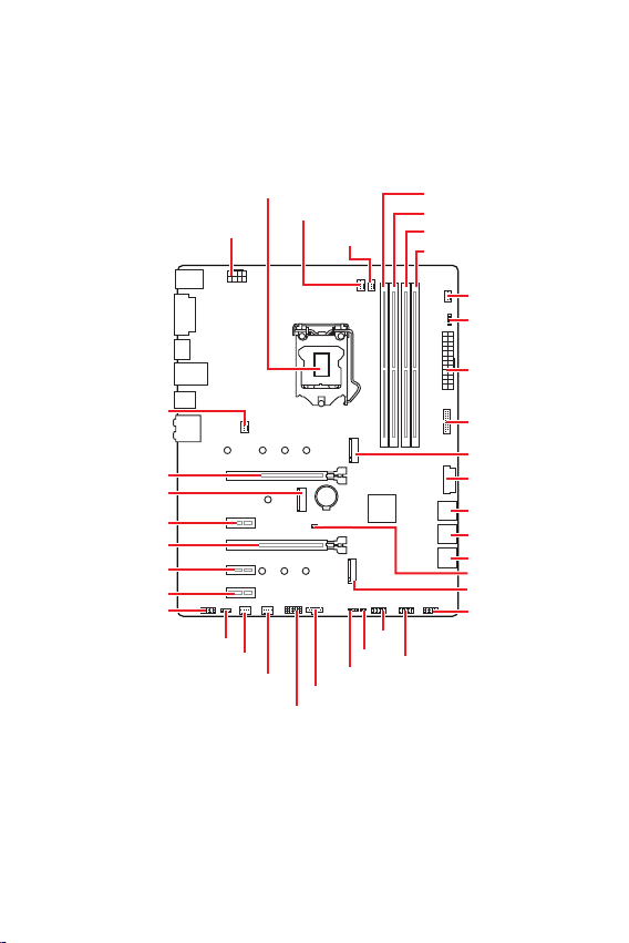
Overview of Components ................................................................................ 7
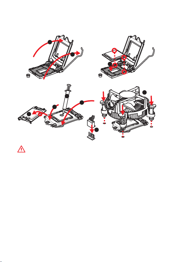
CPU Socket .........................................................................................................8
DIMM Slots..........................................................................................................9
PCI_E1~E5: PCIe Expansion Slots....................................................................10
M2_1~2: M.2 Slots (Key M)................................................................................10
JFP1, JFP2: Front Panel Connectors ...............................................................11
SATA1~6: SATA 6Gb/s Connectors....................................................................11
ATX_PWR1, CPU_PWR1: Power Connectors....................................................12
JAUD1: Front Audio Connector.........................................................................12
JUSB1~2: USB 2.0 Connectors.........................................................................13
JUSB3~4: USB 3.1 Gen1 Connector .................................................................13
JTPM1: TPM Module Connector.......................................................................14
JTBT1: Thunderbolt Add-on Card Connector...................................................14
JRGB1: RGB LED connector.............................................................................14
CPU_FAN1, PUMP_FAN1, SYS_FAN1~4: Fan Connectors...............................15
EZ Debug LED...................................................................................................15
JCI1: Chassis Intrusion Connector...................................................................16
JBAT1: Clear CMOS (Reset BIOS) Jumper .......................................................16
BIOS Setup.....................................................................................................17
Entering BIOS Setup.........................................................................................17
Resetting BIOS..................................................................................................18
Updating BIOS...................................................................................................18
Installing OS, Drivers & Utilities ...................................................................19
Installing Windows®10.....................................................................................19
Installing Drivers ..............................................................................................19
Installing Utilities..............................................................................................19
Thank you for purchasing the MSI®Z390-S01 motherboard.
This User Guide gives information about board layout, com-
ponent overview, BIOS setup and software installation.

2Safety Information
Safety Information
yThe components included in this package are prone to damage from electrostatic
discharge (ESD). Please adhere to the following instructions to ensure successful
computer assembly.
yEnsure that all components are securely connected. Loose connections may cause
the computer to not recognize a component or fail to start.
yHold the motherboard by the edges to avoid touching sensitive components.
yIt is recommended to wear an electrostatic discharge (ESD) wrist strap when
handling the motherboard to prevent electrostatic damage. If an ESD wrist strap is
not available, discharge yourself of static electricity by touching another metal object
before handling the motherboard.
yStore the motherboard in an electrostatic shielding container or on an anti-static
pad whenever the motherboard is not installed.
yBefore turning on the computer, ensure that there are no loose screws or metal
components on the motherboard or anywhere within the computer case.
yDo not boot the computer before installation is completed. This could cause
permanent damage to the components as well as injury to the user.
yIf you need help during any installation step, please consult a certified computer
technician.
yAlways turn off the power supply and unplug the power cord from the power outlet
before installing or removing any computer component.
yKeep this user guide for future reference.
yKeep this motherboard away from humidity.
yMake sure that your electrical outlet provides the same voltage as is indicated on
the PSU, before connecting the PSU to the electrical outlet.
yPlace the power cord such a way that people can not step on it. Do not place
anything over the power cord.
yAll cautions and warnings on the motherboard should be noted.
yIf any of the following situations arises, get the motherboard checked by service
personnel:
Liquid has penetrated into the computer.
The motherboard has been exposed to moisture.
The motherboard does not work well or you can not get it work according to
user guide.
The motherboard has been dropped and damaged.
The motherboard has obvious sign of breakage.
yDo not leave this motherboard in an environment above 60C (140F), it may
damage the motherboard.

3
Safety Information Specifications
Specifications
CPU
Supports 9th/ 8th Gen Intel®Core™ / Pentium®Gold/ Celeron®
processors for LGA 1151 socket
* Please go to www.intel.com for more compatibility
information.
Chipset Intel®Z390 Chipset
Memory
y4x DDR4 memory slots, support up to 64GB*
ySupports DDR4 4400(OC)/ 4300(OC)/ 4266(OC)/ 4200(OC)/
4133(OC)/ 4000(OC)/ 3866(OC)/ 3733(OC)/ 3600(OC)/ 3466(OC)/
3400(OC)/ 3333(OC)/ 3300(OC)/ 3200(OC)/ 3000(OC) /2800(OC)/
2666/ 2400/ 2133 MHz*
ySupports Dual-Channel mode
ySupports non-ECC, un-buffered memory
ySupports Intel®Extreme Memory Profile (XMP)
* Please refer www.msi.com for more information on
compatible memory.
Expansion Slots
y2x PCIe 3.0 x16 slots, support x16/ x4 mode
y3x PCIe 3.0 x1 slots
y1x M.2 slot (Key E) for an Intel®CNVi wireless module only
Onboard
Graphics
y1x DVI-I port, supports a maximum resolution of
1920x1200@60Hz
y1x DisplayPort, supports a maximum resolution of
4096x2304@60Hz
Multi-GPU ySupports 2-Way AMD®CrossFire™ Technology
Storage
Intel®Z390 Chipset
y6x SATA 6Gb/s ports*/**
y2x M.2 slots (Key M)
M2_1 supports up to PCIe 3.0 x4 and SATA 6Gb/s, 2242/
2260/ 2280/ 22110 storage devices*
M2_2 supports up to PCIe 3.0 x4 and SATA 6Gb/s, 2242/
2260/ 2280 storage devices**
* The SATA2 will be unavailable when installing M.2 SATA
device into M2_1 slot.
** The SATA5 &6 will be unavailable when installing M.2 PCIe/
SATA device into M2_2 slot.
Continued on next page

4Specifications
Continued from previous page
USB
Intel®Z390 Chipset
y2x USB 3.1 Gen2 (SuperSpeed USB 10Gbps) ports (1 Type-A
port and 1 Type-C port) on the back panel
y8x USB 3.1 Gen1 (SuperSpeed USB) ports (4 Type-A ports
on the back panel, 4 ports available through the internal USB
3.1 connectors)
y4x USB 2.0 (High-speed USB) ports available through the
internal USB 2.0 connectors
Audio
yRealtek®ALC892 Codec
y7.1-Channel High Definition Audio
ySupports S/PDIF output
LAN 1x Realtek RTL8111H Gigabit LAN controller
I/O Controller NUVOTON NCT6797 Controller Chip
Hardware
Monitor
yCPU/System temperature detection
yCPU/System fan speed detection
yCPU/System fan speed control
Form Factor yATX Form Factor
y12 in. x 9.6 in. (30.5 cm x 24.4 cm)
BIOS Features
y1x 128 Mb flash
yUEFI AMI BIOS
yACPI 6.1, SM BIOS 2.8
yMulti-language
Back Panel
Connectors
y1x PS/2 keyboard/ mouse port
y1x DVI-I port
y1x DisplayPort
y4x USB 3.1 Gen1 Type-A ports
y1x LAN (RJ45) port
y1x USB 3.1 Gen2 Type-A port
y1x USB 3.1 Gen2 Type-C port
y5x OFC audio jacks
y1x Optical S/PDIF OUT connector
Continued on next page

5
Specifications Specifications
Continued from previous page
Internal
Connectors
y1x 24-pin ATX main power connector
y1x 8-pin ATX 12V power connector
y6x SATA 6Gb/s connectors
y3x M.2 slots (2 M-Key slots,1 E-Key slot)
y2x USB 3.1 Gen1 connectors support additional 4 USB 3.1
Gen1 ports
y2x USB 2.0 connectors support additional 4 USB 2.0 ports
y1x Clear CMOS jumper
y2x Front panel connectors
y1x TPM module connector
y1x Chassis Intrusion connector
y1x Front panel audio connector
y1x 4-pin CPU fan connector
y1x 4-pin Water Pump connector
y4x 4-pin system fan connectors
y1x Thunderbolt Add-on card connector
Dragon Center
Features
yOC Performance
yHardware Monitor
yEyerest
yLAN Manager
yLive Update
Please refer to http://download.msi.
com/manual/mb/DRAGONCENTER2.
pdf for more details.
Software
yDrivers
yDRAGON CENTER
yMYSTIC LIGHT
yCPU-Z MSI GAMING
yIntel®Extreme Tuning Utility
yGoogle Chrome™, Google Toolbar, Google Drive
yNorton™ Internet Security Solution

6Rear I/O Panel
Rear I/O Panel
PS/2
Link/ Activity LED
Status Description
Off No link
Yellow Linked
Blinking Data activity
Speed LED
Status Description
Off 10 Mbps connection
Green 100 Mbps connection
Orange 1 Gbps connection
LAN Port LED Status Table
LAN
DisplayPort
USB 3.1 Gen1
DVI-I
USB 3.1 Gen1
USB 3.1
Gen2
Type-A
USB 3.1 Gen2
Type-C
Audio Ports Configuration
Audio Ports Channel
2468
Center/
Subwoofer Out
Rear Speaker Out
Line-In/
Side Speaker Out
Line-Out/
Front Speaker Out
Mic In
(: connected, Blank: empty)
Audio Ports
Optical S/PDIF-Out

7
Rear I/O Panel Overview of Components
CPU_FAN1
PUMP_FAN1
ATX_PWR1
JUSB4
Debug LEDs
SYS_FAN4
CPU Socket
PCI_E2
CNVI_1
PCI_E1
SYS_FAN1
PCI_E3
PCI_E4
PCI_E5
JAUD1
JTBT1
JUSB2
JUSB1
DIMMA1
DIMMA2
DIMMB1
DIMMB2
JUSB3
JCI1
JFP2
CPU_PWR1
SYS_FAN3
SYS_FAN2
JTPM1
JRGB1
SATA3_4
SATA1_2
SATA5_6
JBAT1
JFP1
M2_1
M2_2
BAT1
Overview of Components

8Overview of Components
CPU Socket
Please install the CPU into the CPU socket as shown below.
Important
y
Always unplug the power cord from the power outlet before installing or removing
the CPU.
y
Please retain the CPU protective cap after installing the processor. MSI will deal
with Return Merchandise Authorization (RMA) requests if only the motherboard
comes with the protective cap on the CPU socket.
y
When installing a CPU, always remember to install a CPU heatsink. A CPU heatsink
is necessary to prevent overheating and maintain system stability.
y
Confirm that the CPU heatsink has formed a tight seal with the CPU before booting
your system.
y
Overheating can seriously damage the CPU and motherboard. Always make sure
the cooling fans work properly to protect the CPU from overheating. Be sure to apply
an even layer of thermal paste (or thermal tape) between the CPU and the heatsink to
enhance heat dissipation.
y
Whenever the CPU is not installed, always protect the CPU socket pins by covering
the socket with the plastic cap.
y
If you purchased a separate CPU and heatsink/ cooler, Please refer to the
documentation in the heatsink/ cooler package for more details about installation.
1
4
6
5
78
9
3
2

9
Overview of Components Overview of Components
DIMM Slots
Please install the memory module into the DIMM slot as shown below.
Important
y
Always insert memory modules in the DIMMA2 slot first.
y
Due to chipset resource usage, the available capacity of memory will be a little less
than the amount of installed.
y
Please note that the maximum capacity of addressable memory is 4GB or
less for 32-bit Windows OS due to the memory address limitation. Therefore, we
recommended that you to install 64-bit Windows OS if you want to install more than
4GB memory on the motherboard.
1
12
3
3
2
Memory module installation recommendation
DIMMB2 DIMMB2
DIMMB1
DIMMA2 DIMMA2 DIMMA2
DIMMA1

10 Overview of Components
BAT1
PCI_E1~E5: PCIe Expansion Slots
PCI_E1: PCIe 3.0 x16 (CPU lanes)
PCI_E3: PCIe 3.0 x4 (PCH lanes)
PCI_E2: PCIe 3.0 x1 (PCH lanes)
PCI_E4: PCIe 3.0 x1 (PCH lanes)
PCI_E5: PCIe 3.0 x1 (PCH lanes)
Important
y
If you install a large and heavy graphics card, you need to use a tool such as MSI
Gaming Series Graphics Card Bolster to support its weight to prevent deformation of
the slot.
y
When adding or removing expansion cards, always turn off the power supply and
unplug the power supply power cable from the power outlet. Read the expansion
cards documentation to check for any necessary additional hardware or software
changes.
M2_1~2: M.2 Slots (Key M)
Please install the M.2 solid-state drive (SSD) into the M.2 slot as shown below.
1
2
3
4
5
Important
y
Intel®RST only supports PCIe M.2 SSD with UEFI ROM.
y
Intel®Optane™ Memory Ready.
30

11
Overview of Components Overview of Components
SATA1~6: SATA 6Gb/s Connectors
These connectors are SATA 6Gb/s interface ports. Each connector can connect to one
SATA device.
SATA1
SATA3
SATA5
SATA2
SATA4
SATA6
Important
y
Please do not fold the SATA cable at a 90-degree angle. Data loss may result during
transmission otherwise.
y
SATA cables have identical plugs on either sides of the cable. However, it is
recommended that the flat connector be connected to the motherboard for space
saving purposes.
JFP1, JFP2: Front Panel Connectors
These connectors connect to the switches and LEDs on the front panel.
1
2 10
9
JFP1
1 HDD LED + 2 Power LED +
3 HDD LED - 4 Power LED -
5 Reset Switch 6 Power Switch
7 Reset Switch 8 Power Switch
9 Reserved 10 No Pin
1
JFP2
1 Speaker - 2 Buzzer +
3 Buzzer - 4 Speaker +
HDD LED
RESET SW
HDD LED HDD LED -
HDD LED +
POWER LED -
POWER LED +
POWER LED
JFP1

12 Overview of Components
ATX_PWR1, CPU_PWR1: Power Connectors
These connectors allow you to connect an ATX power supply.
24
131
12
ATX_PWR1
1 +3.3V 13 +3.3V
2 +3.3V 14 -12V
3 Ground 15 Ground
4 +5V 16 PS-ON#
5 Ground 17 Ground
6 +5V 18 Ground
7 Ground 19 Ground
8 PWR OK 20 Res
9 5VSB 21 +5V
10 +12V 22 +5V
11 +12V 23 +5V
12 +3.3V 24 Ground
5
41
8
CPU_PWR1
1 Ground 5 +12V
2 Ground 6 +12V
3 Ground 7 +12V
4 Ground 8 +12V
Important
Make sure that all the power cables are securely connected to a proper ATX power
supply to ensure stable operation of the motherboard.
JAUD1: Front Audio Connector
This connector allow you to connect audio jacks on the front panel.
1
2 10
9
1 MIC L 2 Ground
3 MIC R 4 NC
5 Head Phone R 6 MIC Detection
7 SENSE_SEND 8 No Pin
9 Head Phone L 10 Head Phone Detection

13
Overview of Components Overview of Components
JUSB3~4: USB 3.1 Gen1 Connector
These connectors allow you to connect USB 3.1 Gen1 ports on the front panel.
1
10 11
20
1Power 11 USB2.0+
2 USB3_RX_DN 12 USB2.0-
3 USB3_RX_DP 13 Ground
4 Ground 14 USB3_TX_C_DP
5 USB3_TX_C_DN 15 USB3_TX_C_DN
6 USB3_TX_C_DP 16 Ground
7 Ground 17 USB3_RX_DP
8 USB2.0- 18 USB3_RX_DN
9 USB2.0+ 19 Power
10 GND 20 No Pin
Important
Note that the Power and Ground pins must be connected correctly to avoid possible
damage.
JUSB1~2: USB 2.0 Connectors
These connectors allow you to connect USB 2.0 ports on the front panel.
1
2 10
9
1VCC 2VCC
3 USB0- 4 USB1-
5 USB0+ 6 USB1+
7 Ground 8 Ground
9 No Pin 10 NC
Important
y
Note that the VCC and Ground pins must be connected correctly to avoid possible
damage.
y
In order to recharge your iPad,iPhone and iPod through USB ports, please install
MSI Dragon Center utility.

14 Overview of Components
JTPM1: TPM Module Connector
This connector is for TPM (Trusted Platform Module). Please refer to the TPM
security platform manual for more details and usages.
1
2 14
13
1 LPC Clock 2 3V Standby power
3 LPC Reset 4 3.3V Power
5 LPC address & data pin0 6 Serial IRQ
7 LPC address & data pin1 8 5V Power
9 LPC address & data pin2 10 No Pin
11 LPC address & data pin3 12 Ground
13 LPC Frame 14 Ground
JTBT1: Thunderbolt Add-on Card Connector
This connector allows you to connect the add-on Thunderbolt I/O card.
11 FORCE_PWR 2 SCI_EVENT
3 SLP_S3# 4 SLP_S5#
5 Ground
Important
y
The JRGB1 connector supports 5050 RGB LED strip (12V/G/R/B) with the maximum
power rating of 3A (12V).
y
Please keeping the LED strip shorter than 2 meters to prevent dimming.
y
Always turn off the power supply and unplug the power cord from the power outlet
before installing or removing the LED strip.
y
Please use MSIs software to control the extended LED strip.
JRGB1: RGB LED connector
The JRGB1 connector allows you to connect the 5050 RGB LED strips 12V.
1
1 +12V 2 G
3 R 4 B

15
Overview of Components Overview of Components
EZ Debug LED
These LEDs indicate the status of the motherboard.
CPU - indicates CPU is not detected or fail.
DRAM - indicates DRAM is not detected or fail.
VGA - indicates GPU is not detected or fail.
BOOT - indicates booting device is not detected or fail.
CPU_FAN1, PUMP_FAN1, SYS_FAN1~4: Fan Connectors
Fan connectors are classified as PWM (Pulse Width Modulation) Mode. PWM Mode
fan connectors provide constant 12V output and adjust fan speed with speed control
signal. When you plug a 3-pin (Non-PWM) fan to a fan connector in PWM mode, the
fan speed will always maintain at 100%, which might create a lot of noise.
PWM Mode pin definition
1 Ground 2 +12V
3 Sense 4 Speed Control
Signal
There are gradient points of the fan speed that allow you to
adjust fan speed in relation to CPU temperature.
1
SYS_FAN2/ 3
1
CPU_FAN1/ PUMP_FAN1/
SYS_FAN1/ SYS_FAN4
Pin definition of fan connectors

16 Overview of Components
JBAT1: Clear CMOS (Reset BIOS) Jumper
There is CMOS memory onboard that is external powered from a battery located on
the motherboard to save system configuration data. If you want to clear the system
configuration, set the jumper to clear the CMOS memory.
Keep Data
(default) Clear CMOS/
Reset BIOS
Resetting BIOS to default values
1. Power off the computer and unplug the power cord
2. Use a jumper cap to short JBAT1 for about 5-10 seconds.
3. Remove the jumper cap from JBAT1.
4. Plug the power cord and power on the computer.
JCI1: Chassis Intrusion Connector
This connector allows you to connect the chassis intrusion switch cable.
Normal
(default) Trigger the chassis
intrusion event
Using chassis intrusion detector
1. Connect the JCI1 connector to the chassis intrusion switch/ sensor on the chassis.
2. Close the chassis cover.
3. Go to BIOS > SETTINGS > Security > Chassis Intrusion Configuration.
4. Set Chassis Intrusion to Enabled.
5. Press F10 to save and exit and then press the Enter key to select Yes.
6. Once the chassis cover is opened again, a warning message will be displayed on
screen when the computer is turned on.
Resetting the chassis intrusion warning
1. Go to BIOS > SETTINGS > Security > Chassis Intrusion Configuration.
2. Set Chassis Intrusion to Reset.
3. Press F10 to save and exit and then press the Enter key to select Yes.

17
Overview of Components BIOS Setup
BIOS Setup
The default settings offer the optimal performance for system stability in normal
conditions. You should always keep the default settings to avoid possible system
damage or failure booting unless you are familiar with BIOS.
Important
y
BIOS items are continuously update for better system performance. Therefore, the
description may be slightly different from the latest BIOS and should be for reference
only. You could also refer to the HELP information panel for BIOS item description.
y
The pictures in this chapter are for reference only and may vary from the product
you purchased.
Entering BIOS Setup
Please refer the following methods to enter BIOS setup.
yPress Delete key, when the Press DEL key to enter Setup Menu, F11 to enter Boot
Menu message appears on the screen during the boot process.
yUse MSI Dragon Center application. Click on GO2BIOS button and choose OK. The
system will reboot and enter BIOS setup directly.
Function key
F1: General Help
F2: Add/ Remove a favorite item
F3: Enter Favorites menu
F4: Enter CPU Specifications menu
F5: Enter Memory-Z menu
F6: Load optimized defaults
F7: Switch between Advanced mode and EZ mode
F8: Load Overclocking Profile
F9: Save Overclocking Profile
F10: Save Change and Reset*
F12: Take a screenshot and save it to USB flash drive (FAT/ FAT32 format only).
Ctrl+F: Enter Search page
* When you press F10, a confirmation window appears and it provides the
modification information. Select between Yes or No to confirm your choice.

18 BIOS Setup
Resetting BIOS
You might need to restore the default BIOS setting to solve certain problems. There
are several ways to reset BIOS:
yGo to BIOS and press F6 to load optimized defaults.
yShort the Clear CMOS jumper on the motherboard.
Important
Be sure the computer is off before clearing CMOS data. Please refer to the Clear
CMOS jumper section for resetting BIOS.
Updating BIOS
Updating BIOS with M-FLASH
Before updating:
Please download the latest BIOS file that matches your motherboard model from MSI
website. And then save the BIOS file into the USB flash drive.
Updating BIOS:
1. Insert the USB flash drive that contains the update file into the USB port.
2. Please refer the following methods to enter flash mode.
Reboot and press Ctrl + F5 key during POST and click on Yes to reboot the
system.
Reboot and press Del key during POST to enter BIOS. Click the M-FLASH
button and click on Yes to reboot the system.
3. Select a BIOS file to perform the BIOS update process.
4. After the flashing process is 100% completed, the system will reboot
automatically.
Updating the BIOS with MSI Dragon Center
Before updating:
Make sure the LAN driver is already installed and the Internet connection is set
properly.
Updating BIOS:
1. Install and launch MSI Dragon Center.
2. Select BIOS Update.
3. Click on Scan button.
4. Click on Download icon to download and install the latest BIOS file.
5. Click Next and choose In Windows mode. And then click Next and Start to start
updating BIOS.
6. After the flashing process is 100% completed, the system will restart
automatically.

19
BIOS Setup Installing OS, Drivers & Utilities
Installing OS, Drivers & Utilities
Please download and update the latest utilities and drivers at www.msi.com
Installing Windows®10
1. Power on the computer.
2. Insert the Windows®10 installation disc/USB into your computer.
3. Press the Restart button on the computer case.
4. Press F11 key during the computer POST (Power-On Self Test) to get into Boot
Menu.
5. Select the Windows®10 installation disc/USB from the Boot Menu.
6. Press any key when screen shows Press any key to boot from CD or DVD...
message.
7. Follow the instructions on the screen to install Windows®10.
Installing Drivers
1. Start up your computer in Windows®10.
2. Insert MSI®Driver Disc into your optical drive.
3. Click the Select to choose what happens with this disc pop-up notification, then
select Run DVDSetup.exe to open the installer. If you turn off the AutoPlay feature
from the Windows Control Panel, you can still manually execute the DVDSetup.exe
from the root path of the MSI Driver Disc.
4. The installer will find and list all necessary drivers in the Drivers/Software tab.
5. Click the Install button in the lower-right corner of the window.
6. The drivers installation will then be in progress, after it has finished it will prompt
you to restart.
7. Click OK button to finish.
8. Restart your computer.
Installing Utilities
Before you install utilities, you must complete drivers installation.
1. Open the installer as described above.
2. Click the Utilities tab.
3. Select the utilities you want to install.
4. Click the Install button in the lower-right corner of the window.
5. The utilities installation will then be in progress, after it has finished it will prompt
you to restart.
6. Click OK button to finish.
7. Restart your computer.

Table of contents
Languages:
Other MSI Motherboard manuals

MSI
MSI MAG B460 TOMAHAWK User manual

MSI
MSI X370 GAMING M7 ACK User manual

MSI
MSI PRO Z790-A WIFI User manual

MSI
MSI MS-6507 User manual

MSI
MSI MS-6567 User manual

MSI
MSI MS-7204 User manual

MSI
MSI MS-9641 User manual

MSI
MSI X99A SLI PLUS User manual

MSI
MSI B550M PRO-VDH WIFI User manual

MSI
MSI MS-98G6 User manual

MSI
MSI MPG Z490 GAMING EDGE WIFI User manual

MSI
MSI 945G Neo User manual

MSI
MSI RX480 Neo2 User manual

MSI
MSI MS-9802 User manual

MSI
MSI 915GM Speedster MS-9625 User manual

MSI
MSI K8NGM-V Series User manual

MSI
MSI B450M BAZOOKA User manual

MSI
MSI K8N Neo Platinum User manual

MSI
MSI B550-A PRO User manual

MSI
MSI H110I PRO User manual