MSI 790FX-GD70 Series User manual

790FX-GD70Series
MS-7577(v1.X)Mainboard
G52-75771X1

ii
CopyrightNotice
The materialinthisdocumentistheintellectual propertyof MICRO-STAR
INTERNATIONAL.Wetakeeverycareinthe preparationof thisdocument, butno
guaranteeisgivenastothecorrectnessofitscontents.Ourproductsareunder
continualimprovementand wereservetherighttomakechangeswithoutnotice.
Trademarks
Alltrademarksarethepropertiesoftheirrespectiveowners.
NVIDIA,theNVIDIAlogo,DualNet, and nForceareregisteredtrademarksortrade-
marksofNVIDIACorporationin theUnitedStatesand/orothercountries.
AMD,Athlon ,Athlon XP,Thoroughbred ,andDuron areregisteredtrade-
marksofAMDCorporation.
Intel®andPentium®areregisteredtrademarksofIntelCorporation.
PS/2and OS®/2areregisteredtrademarksofInternationalBusiness Machines
Corporation.
Windows®NT/XP/VistaareregisteredtrademarksofMicrosoftCorporation.
Netware®isaregisteredtrademarkofNovell,Inc.
Award®isaregisteredtrademarkofPhoenixTechnologiesLtd.
AMI®isaregisteredtrademarkofAmericanMegatrendsInc.
RevisionHistory
Revision RevisionHistory Date
V1.0 First Release January2009
TechnicalSupport
Ifaproblemariseswithyoursystemandnosolutioncanbeobtainedfromtheuser’s
manual,pleasecontactyourplaceofpurchaseorlocaldistributor.Alternatively,
pleasetrythefollowing helpresourcesforfurtherguidance.
Visit theMSI websiteforFAQ,technical guide,BIOSupdates,driverupdates,
andotherinformation: http://global.msi.com.tw/index.php?
func=service
Contactourtechnicalstaff at: http://ocss.msi.com.tw

iii
SafetyInstructions
CAUTION: Dangerofexplosionifbatteryisincorrectlyreplaced.
Replaceonlywiththe sameorequivalenttype recommendedbythe
manufacturer.
1. Alwaysread thesafetyinstructionscarefully.
2. KeepthisUser’sManualforfuturereference.
3. Keepthisequipmentawayfromhumidity.
4. Laythisequipmentonareliableflatsurfacebeforesetting itup.
5. Theopeningsontheenclosureareforairconvectionhenceprotectstheequip-
ment fromoverheating.DONOTCOVERTHEOPENINGS.
6. Makesurethevoltageofthe powersourceandadjustproperly110/220Vbe-
foreconnectingtheequipmenttothepowerinlet.
7. Placethe powercordsuchawaythatpeoplecannotstepon it. Donotplace
anythingoverthepowercord.
8. AlwaysUnplug thePowerCordbeforeinsertinganyadd-oncardormodule.
9. All cautionsand warningsontheequipmentshouldbenoted.
10. Neverpouranyliquidintotheopeningthatcoulddamage orcauseelectrical
shock.
11. If anyof thefollowing situationsarises, gettheequipmentcheckedbyaservice
personnel:
†Thepowercordorplugisdamaged.
†Liquid haspenetratedintotheequipment.
†Theequipmenthasbeen exposedtomoisture.
†Theequipmenthasnotworkwelloryoucannotgetitworkaccording to
User’sManual.
†Theequipmenthasdroppedand damaged.
†Theequipmenthasobvioussign of breakage.
12.DONOTLEAVETHISEQUIPMENTINANENVIRONMENTUNCONDITIONED,STOR-
AGETEMPERATUREABOVE600C(1400F),IT MAYDAMAGETHEEQUIPMENT.

iv
FCC-BRadio Frequency Interference Statement
Thisequipmenthasbeen
tested and found tocomply
withthe limitsforaClassB
digitaldevice,pursuanttoPart
15of the FCCRules.Theselimitsaredesignedtoprovidereasonable protection
againstharmful interferenceinaresidentialinstallation.Thisequipmentgenerates,
usesand canradiateradiofrequencyenergyand,ifnotinstalledand used in accor-
dancewiththeinstructions,maycauseharmful interferencetoradiocommunications.
However,thereisno guarantee thatinterferencewill notoccurin aparticular
installation.Ifthisequipmentdoescauseharmful interferencetoradioortelevision
reception,whichcanbedeterminedbyturning theequipmentoff and on,the useris
encouragedtotrytocorrecttheinterferencebyone ormoreof themeasureslisted
below.
†Reorientorrelocatethereceiving antenna.
†Increasetheseparationbetweentheequipmentand receiver.
†Connecttheequipmentintoanoutleton acircuitdifferentfromthatto
whichthereceiverisconnected.
†Consultthedealeroranexperiencedradio/televisiontechnicianforhelp.
Notice1
Thechangesormodificationsnotexpresslyapprovedbythepartyresponsible for
compliancecould void theuser’sauthoritytooperatetheequipment.
Notice2
Shieldedinterfacecablesand A.C.powercord,ifany,mustbeusedinorderto
complywiththeemissionlimits.
VOIRLANOTICED’ INSTALLATIONAVANTDERACCORDERAURESEAU.
Micro-StarInternational
MS-7577
ThisdevicecomplieswithPart15oftheFCCRules.Operationissubjecttothe
followingtwoconditions:
(1)thisdevicemaynotcauseharmfulinterference,and
(2)thisdevicemustaccept anyinterferencereceived,includinginterferencethat
maycauseundesiredoperation.

v
WEEE (WasteElectricaland ElectronicEquipment) Statement

vi

vii

CONTENTS
CopyrightNotice..............................................................................................................ii
Trademarks.......................................................................................................................ii
RevisionHistory..............................................................................................................ii
Technical Support...........................................................................................................ii
SafetyInstructions.........................................................................................................iii
FCC-B RadioFrequencyInterferenceStatement........................................................iv
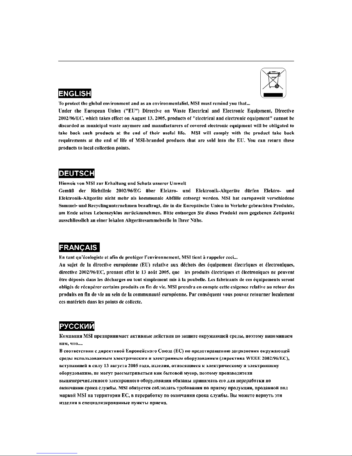
WEEE(WasteElectricalandElectronicEquipment)Statement....................................v
Chapter1.GettingStarted....................................................................................1-1
MainboardSpecifications...................................................................................1-2
MainboardLayout................................................................................................1-4
PackingChecklist.................................................................................................1-5
Chapter2.HardwareSetup..................................................................................2-1
Quick ComponentsGuide....................................................................................2-2
CPU(CentralProcessingUnit)............................................................................2-3
Memory.................................................................................................................2-6
PowerSupply......................................................................................................2-8
BackPanel............................................................................................................2-9
Connectors.........................................................................................................2-11
Button.................................................................................................................2-19
Slots....................................................................................................................2-22
LEDStatusIndicators........................................................................................2-26
Chapter3BIOSSetup.............................................................................................3-1
EnteringSetup.....................................................................................................3-2
TheMainMenu.....................................................................................................3-4
StandardCMOSFeatures...................................................................................3-6
AdvancedBIOSFeatures...................................................................................3-8
IntegratedPeripherals........................................................................................3-11
PowerManagementSetup...............................................................................3-13
H/WMonitor........................................................................................................3-16
GreenPower.....................................................................................................3-17
BIOSSetting Password.....................................................................................3-18
Cell Menu............................................................................................................3-19
UserSetting.......................................................................................................3-26
M-Flash...............................................................................................................3-27
LoadFail-Safe/Optimized Defaults.................................................................3-30

AppendixARealtekAudio...................................................................................A-1
InstallingtheRealtekHDAudioDriver................................................................A-2
SoftwareConfiguration......................................................................................A-4
HardwareSetup................................................................................................A-19
AppendixBOverclocking Center.......................................................................B-1
Activating Overclocking Center ......................................................................... B-2
SystemInfo..........................................................................................................B-3
DOT.......................................................................................................................B-5
AppendixCSB750 SATARAID..............................................................................C-1
RAIDConfiguration..............................................................................................C-2
AppendixDDriveBoosterManager...................................................................D-1
Introduction..........................................................................................................D-2
RAIDConfiguration..............................................................................................D-3

1-1
Getting Started
Getting Started
Chapter1
Thankyouforchoosing the790FX-GD70Series(MS-
7577 v1.X) ATXmotherboard. The 790FX-GD70Series
motherboardsarebasedon AMD 790FX & SB750
chipsetforoptimalsystemefficiency.Designedtofit
the advanced AMD PhenomII X4/X3 and Athlon
X4/X3/X2AM3 processor,the 790FX-GD70Series
deliverahigh performanceandprofessionaldesktop
platformsolution.

MS-7577Mainboard
1-2
ProcessorSupport
-SupportsAMD PhenomTM IIX4/X3andAthlonX4/ X3/ X2
processorsin theAM3package
(ForthelatestinformationaboutCPU,pleasevisit http://global.
msi.com.tw/index.php?func=cpuform2)
HyperTransport
-SupportsHyperTransport3.0up to5.2GT/s
Chipset
-NorthBridge:AMD 790FXchipset
-SouthBridge:AMD SB750chipset
MemorySupport
-DDR31066/1333/1600*/1800*/2133*SDRAM(total 16GBMax)
-4DDR3DIMMs(240pin / 1.5V)
(*meansoverclock,formoreinformationon compatible
components,pleasevisithttp://global.msi.com.tw/index.php?
func=testreport)
LAN
-SupportsDualGigabitLANbyRealtek RTL8111DL
IEEE 1394 (optional)
-Chip integratedbyVIA VT6315N
-Supports2IEEE1394 ports(rearx1,frontx1)
Audio
-HDAudio Realtek ALC889
-Upto8-channelaudiowithjacksensing
IDE
-1IDEport byAMD SB750
-SupportsUltraDMA66/100/133mode
-SupportsPIO, BusMasteroperationmode
SATA
-SATA1~6portsbyAMD SB750
-SATA7~8 portsbyJMicron JMB322
-Supportsstorageand datatransfersatup to3.0Gb/s
ESATA
-Supports1E-SATAportbyJMicron JMB362
-Supportsstorageand datatransfersatup to3.0Gb/s
RAID
-SATA1~6 supportsRAID0/1/10/5orJBODmodebyAMD SB750
MotherboardSpecifications

1-3
Getting Started
HardwareRAID
-SATA7&SATA8supportRAID0/ 1&JBODmodebyJMicron
JMB322
Floppy
-1floppyport
-Supports1FDD with360KB,720KB,1.2MB,1.44 MBand
2.88MB
Connectors
Back panel
-1PS/2mouse/ 1PS/2keyboardport
-1Coaxial S/PDIF-outjack/1Optical S/PDIF-outport
-7USB2.0Ports
-1E-SATA/USBcommonport
-1IEEE1394port(optional)
-2LANjacks
-6flexibleaudio jacks
On-BoardPinheaders/Connectors
-2USB 2.0pinheaders
-1IEEE1394 pinheader(optional)
-1COMport pinheader
-1CD-in pinheader
-1TPMModule pinheader
-1ChassisIntrusionpinheader
-1FrontPanel Audiopinheader
-1S/PDIF-outpinheader
-1DebugLED
Slots
-4PCIExpress gen2 x16 slots,supportCrossFireXTM technology
a.thePCIEx16 slots(PCI_E1&PCI_E4)supportuptoPCIE2.0x16
speed
b. thePCIEx16 slots(PCI_E3&PCI_E5)support up toPCIE2.0x8
speed)
c.if youintend toinstall fourexpansioncardsintoall PCIEx16
slots,thesefourPCIEx16laneswill autoarrangefrom
x16/ x16/x0/x0tox8/x8/x8/x8
-1PCIExpress gen2 x1slot
-2PCIslots
FormFactor
-ATX(30.4cm X24.5cm)
Mounting
-9mounting holes

MS-7577Mainboard
1-4
790FX-GD70Series
(MS-7577v1.X)ATXMotherboard
MotherboardLayout
BATT
+
PCI_E5
PCI_E1
PCI_E2
PCI_E3
PCI1
PCI2
PCI_E4
SYSFAN4
SYSFAN3
JSP1
JAUD1 JCD1
J1394_1
(Optional)
FDD1
JCOM1
JCI1
POST_LED
JBAT1
JUSB2
JUSB1
JTPM1
SYSFAN2
SATA8
SATA7 IDE1
SYSFAN1
DIMM1
DIMM2
DIMM3
DIMM4
CPUFAN1
JPWM2
JPWR1
JFP1 JFP2
POWER1RESET1
CLR_CMOS1
SATA1-2SATA3-4SATA5-6
Top:mouse
Bottom:
keyboard
Top:LANJack
Bottom:USB ports
Top:LANJack
Bottom:USB ports
T:
M:
B:
Line-In
Line-Out
Mic
T:RS-Out
M:CS-Out
B:SS-Out
Top:1394(optional)
Bottom:USB ports
Top:USB
Buttom:ESATA/USB
Commonport
AMD
790FX
AMD
SB750
I/O
Chip
Clock
Gen.
LAN
chip
LAN
chip
1394
chip
Audio
codec
JMB362
JMB322
Top:
CoaxialS/PDIF
Buttom:
OpticalS/PDIF
GreenPower
OC GEAR
OC DRIVE

1-5
Getting Started
*The picturesareforreferenceonlyandmayvaryfromthepackingcontentsofthe
productyoupurchased.
PackingChecklist
PowerCable
MSImotherboard MSIDriver/UtilityCD
IDE/FloppyCable
Back IOShield
SATACable
USBBracket
CrossFire
VideoLinkCable User’sGuide

2-1
HardwareSetup
HardwareSetup
Chapter2
Thischapterprovidesyou withtheinformation about
hardwaresetupprocedures.Whiledoingthe installation,
becarefulinholdingthecomponentsandfollowthe
installationprocedures.Forsomecomponents,ifyou
install inthewrong orientation,thecomponentswillnot
workproperly.
Useagroundedwrist strapbeforehandlingcomputer
components.Staticelectricitymaydamagethe
components.

MS-7577Mainboard
2-2
Quick ComponentsGuide
JPWM2, p.2-8
CPU, p.2-3
JCI1, p.2-13
DDR3, p.2-6
JPWR1, p.2-8
SYSFAN2, p.2-13
IDE1, p.2-11
JTPM1, p.2-14
SATA, p.2-12
JCOM1, p.2-14
JFP2, p.2-17
JFP1, p.2-17
POWER1, p.2-19
RESET1, p.2-19
CLR_CMOS1, p.2-19
JUSB1~2, p.2-18
FDD1, p.2-11
JCD1, p.2-15
JAUD1, p.2-15
PCISlots,
p.2-25
PCIESlots,
p.2-22
Back Panel,
p.2-9
CPUFAN1, p.2-13
SYSFAN1, p.2-13
SYSFAN3, p.2-13
SYSFAN4, p.2-13
JBAT1, p.2-19
GreenPower, p.2-20
OCGEAR, p.2-20
OCDRIVE, p.2-20
J1394_1, p.2-16
JSP1, p.2-16
POST_LED, p.2-21

2-3
HardwareSetup
CPU(CentralProcessingUnit)
Whenyou areinstalling theCPU, makesuretoinstallthecoolertoprevent
overheating. If youdonothavetheCPUcooler, consultyourdealerbeforeturning
onthecomputer.
Forthelatest informationaboutCPU,pleasevisit http://global.msi.com.tw/index.php?
func=cpuform2
Important
Overheating
Overheating will seriouslydamage the CPUand system.Always makesure
thecoolingfancanworkproperlytoprotectthe CPUfromoverheating.Make
surethatyouapplyan even layerofthermalpaste(orthermaltape)between
the CPUand the heatsinktoenhanceheatdissipation.
Replacing theCPU
WhilereplacingtheCPU,alwaysturnofftheATXpowersupplyorunplug the
powersupply spowercordfromthegrounded outlet firsttoensurethe safety
ofCPU.
Overclocking
Thismotherboardisdesignedtosupportoverclocking.However,please
makesureyourcomponentsareabletotoleratesuchabnormal setting,
whiledoing overclocking.Anyattempttooperatebeyond productspecifica-
tionsisnotrecommended. Wedonotguaranteethedamagesorrisks
causedbyinadequateoperationorbeyond productspecifications.

MS-7577Mainboard
2-4
CPU&Cooler Installation
When youareinstalling theCPU, make suretheCPUhasacoolerattached on
thetoptopreventoverheating. Meanwhile, do notforgettoapplysomethermal
pasteonCPUbeforeinstalling theheatsink/coolerfanforbetterheatdispersion.
Followthestepsbelowtoinstall theCPU&coolercorrectly.Wrong installationwill
causethedamageofyourCPU&motherboard.
1.Pull theleversidewaysawayfrom
thesocket. Makesuretoraisethe
leverup toa90-degree angle.
2.LookforthegoldarrowoftheCPU.
The gold arrowshouldpointas
shownin thepicture.TheCPUcan
onlyfitin thecorrectorientation.
3.If the CPUiscorrectlyinstalled,the
pinsshouldbe completelyembed-
dedintothesocketand cannotbe
seen.Pleasenotethatanyviolation
ofthecorrectinstallationproce-
duresmaycausepermanentdam-
agestoyourmotherboard.
4. Press theCPUdownfirmlyintothe
socketand closethelever.Asthe
CPUislikelytomovewhilethelever
isbeing closed,alwaysclosethe
leverwithyourfingerspressing
tightlyontopoftheCPUtomake
suretheCPUisproperlyand com-
pletelyembeddedintothesocket.

2-5
HardwareSetup
6.Then pressdowntheotherendof
thecliptofastenthecooling seton
thetopof theretentionmechanism.
LocatetheFixLeverand liftup it.
5.Positionthecooling setontothere-
tentionmechanism.
Hookoneend oftheclip tohookfirst.
7.Fastendownthelever. 8.AttachtheCPUFancabletotheCPU
fanconnectoron themotherboard.
1.Motherboardphotosshowninthissection arefordemonstration only.The
appearanceof yourmotherboardmayvarydependingon themodelyou
purchase.
2.Whiledisconnecting the SafetyHookfromthefixedbolt,it isnecessaryto
keepaneyeon yourfingers, becauseoncethe SafetyHookisdisconnected
fromthe fixed bolt, the fixed leverwill spring backinstantly.
Important

MS-7577Mainboard
2-6
Important
-DDR3memorymodulesarenotinterchangeablewithDDR2andthe DDR3
standardisnotbackwardscompatible.You shouldalways install DDR3
memorymodulesinthe DDR3DIMM slots.
-InDual-Channelmode,makesurethat youinstall memorymodulesof the
sametypeand density in differentchannel DIMMslots.
-Toenable successful systemboot-up,alwaysinsertthememorymodules
intothe DIMM1first.
DDR3
240-pin,1.5V
1
DIMM1
DIMM2
DIMM3
DIMM4
2
DIMM1
DIMM2
DIMM3
DIMM4
Dual-ChannelMemory Population Rules
InDual-Channel mode,thememorymodulescantransmitand receivedatawithtwo
databuslinessimultaneously.Enabling Dual-Channelmode canenhancethesystem
performance.Pleaserefertothefollowingillustrationsforpopulationrulesunder
Dual-Channel mode.
72x2=144 pin 48x2=96pin
TheseDIMM slotsareusedforinstalling memorymodules.
Formoreinformationoncompatiblecomponents, pleasevisit http://global.msi.com.
tw/index.php?func=testreport
Memory
Installed
Empty
This manual suits for next models
2
Table of contents
Other MSI Motherboard manuals

MSI
MSI 975X Platinum Series User manual

MSI
MSI MS-6567 User manual

MSI
MSI 990FXA-GD65 Series User manual

MSI
MSI E350DM-E33 series User manual

MSI
MSI D3050 User manual

MSI
MSI MAG B460M BAZOOKA User manual

MSI
MSI BAZOOKA B460M User manual

MSI
MSI MS-98H9 User manual

MSI
MSI MPG Z590 GAMING CARBON WIFI User manual

MSI
MSI 945GM2-FR User manual