MSI MSI-3460 User manual

MSI-3460
Challenger 3
Operator’s Manual
152161 Rev A


Technical training seminars are available through Rice Lake Weighing Systems.
Course descriptions and dates can be viewed at www.ricelake.com/training
or obtained by calling 715-234-9171 and asking for the training department.
Contents
1.0 Introduction ...........................................................................1
1.1 Safety ................................................................................... 2
1.2 General Information ............................................................ 4
1.2.1 User Guide & MSI-3460 Conventions .................................4
1.3 MSI3460 Annunciators ........................................................ 5
1.4 Specifications ...................................................................... 6
1.5 Features ............................................................................... 8
1.6 Options ................................................................................ 8
1.7 Unpacking ........................................................................... 8
1.8 Assembly ............................................................................. 9
1.9 Battery Pack ...................................................................... 10
1.10Battery Charger ................................................................ 11
2.0 Operation .............................................................................12
2.1 Power ................................................................................. 12
2.2 Zero ................................................................................... 12
2.3 Tare .................................................................................... 13
3.0 User Defined Function Keys .................................................14
4.0 Configuration .......................................................................16
4.1 Menu Map ......................................................................... 16
4.2 Function Keys ................................................................... 17
4.3 Auto- Off ............................................................................ 18
4.4 Sleep .................................................................................. 19
4.5 Display Brightness ............................................................ 20
4.6 Set Points .......................................................................... 21
4.7 Total Mode ........................................................................ 23
4.8 Units ................................................................................... 24
4.9 Filter Setup ........................................................................ 25
5.0 Calibration ...........................................................................26
5.1 Initial Calibration ............................................................... 29
5.2 Guidelines for Capacity and Resolution .......................... 30
5.3 C-Cal Calibration ............................................................... 31
5.4 Calibration Setup Menu .................................................... 34
5.5 Standard ............................................................................ 34
5.6 Auto Zero Maintenance .................................................... 35
© 2013Rice Lake Weighing Systems. All rights reserved. Printed in the United States of America.
Specifications subject to change without notice.
Rice Lake Weighing Systems is an ISO 9001 registered company.
February 2013 Rev A

ii MSI3460 Operator’s Manual
6.0 RF Remote Control Option ...................................................37
6.1 Description ........................................................................ 37
6.2 Functions ........................................................................... 37
6.3 Setting the Transmitter Address ...................................... 37
6.4 Setting the Receiver Address ........................................... 38
6.4.1 Resetting the MSI-3460 RF Remote Receiver ..................38
6.5 Contention and Jamming Considerations ....................... 38
6.6 Battery Replacement ........................................................ 39
6.7 RF Remote Control FCC Statement ................................. 39
7.0 RF Remote Display Option ...................................................40
7.1 Introduction ....................................................................... 40
7.2 Printer/Serial Output Setup .............................................. 41
7.2.1 Control Modes .................................................................41
7.3 Standard Print Strings ...................................................... 42
7.4 802.15.4 RF Network Setup .............................................. 44
7.5 FCC Statement (for 802.15.4 Option) ............................... 45
7.6 RF Setup Procedure ......................................................... 45
7.7 International RF CERTS (For 802.15.4 OPTION) .............. 47
8.0 Appendix ..............................................................................48
8.1 Troubleshooting ................................................................ 48
8.1.1 Service Counters ..............................................................50
8.2 MSI-3460 Challenger 3 Dimensions ................................. 51
The MSI Limited Warranty ............................................................52
Rice Lake continually offers web-based video training on a growing selection
of product-related topics at no cost. Visit www.ricelake.com/webinars.

Introduction 1
1.0 Introduction
The MSI-3460 Challenger 3 is a combination of the sound and proven mechanical
design of the industry standard Challenger with today’s most advanced electronics. It
provide a superb feature set unmatched by any scale in its class or price range. The
multi-purpose hanging scale is ideal for situations in which headroom is at a
minimum. The MSI-3460 is versatile, reliable, accurate and easy to operate. The MSI-
3460 is designed to meet or exceed the requirements of all regulatory agencies. RF
remote control and remote display options are available to further enhance the safety
and usability of the MSI-3460.
Please take the time to read this manual completely through before attempting to use
the MSI-3460. Although designed for easy set up and use, a thorough understanding
of this manual will ensure that you receive the maximum benefit from the system.
If you have any questions or comments, please contact
Measurement Systems International
Phone (toll free): 1-800-874-4320
Authorized distributors and their employees can view or download this
manual from the Measurement Systems International site at:
www.msiscales.com.

2 MSI-3460 Operator’s Manual
1.1 Safet y
Safety Symbol Definitions:
Important
WARNING
Indicates a potentially hazardous situation that, if not avoided,
could result in serious injury or death, and includes hazards that
are exposed when guards are removed.
Indicates information about procedures that, if not observed,
could result in damage to equipment or corruption to and loss of
data.
General Safety
WARNING
Do not operate or work on this equipment unless you have read
and understand the instructions and warnings in the Installation,
Operators Manual. Contact any Measurement Systems
International dealer for replacement manuals. Proper care is
your responsibility.
Failure to heed may result in serious injury of death.
DO NOT allow minors (children) or inexperienced persons to operate this unit.
DO NOT stand near the load being lifted as it is a potential falling hazard. Keep a
safe distance.
DO NOT use for purposes other then weight taking or dynamic load monitoring.
DO NOT use any load bearing component that is worn beyond 5% of the original
dimension.
DO NOT use the scale if any of the components of the load train are cracked,
deformed, or show signs of fatigue.
DO NOT exceed the rated load limit of the scale, rigging elements, or the lifting
structure.
DO NOT allow multi-point contact with the hook, shackle, or lifting eye of the
scale.
DO NOT allow high torque on the scale unless it is specifically designed for high
torque.
DO NOT make alterations or modifications to the scale or associated load bearing
devices.
DO NOT use improperly rated or sized shackles. Use only MSI recommended
shackles.
DO NOT remove or obscure warning labels.
For guidelines on the safe rigging and loading of overhead scales and
dynamometers, read the "MSI Crane Scale Safety and Periodic Maintenance
Manual" (available at www.msiscales.com).
Keep hands, feet and loose clothing away from moving parts.
There are no user serviceable parts within the MSI-3460. Any repairs are to be
performed by qualified service personnel only.

5 Digit 1.5/3.8mm
high brightness LED
weight display
Wire sealable
calibration port
Light Sensor for auto
brightness Control User programmable
function key
Introduction 3
Figure 1-1. MSI-3460 Front Panel
Key Descriptions
POWER
Power Key - Turns the MSI-3460on and off.
ZERO
Zero Key - Used to zero out residual weight on the scale.
TARE
Tare Key - removes weight of containers, trucks or carriers and places
the scale in the Net weight mode.
TARE key functions tare in, tare out.
To see the gross weight without resetting the tare value, you must
program the USER key as NET/GROSS.
USER
F
User Key- Programmable to user selectable functions. These are
described in the USER key Setup section. This key is defaulted to the
TEST function.

4 MSI-3460 Operator’s Manual
1.2 General Information
1.2.1 User Guide & MSI-3460 Conventions
1. Keys used in operations are printed in BLUE and capitalized.
2. Screen shots that are used in menus are displayed in RED and shown in a 7-
segment font. Not all characters can be displayed with this font, but a close
approximation is shown.
3. If a function key does not work, it is probably because the MSI-3460 is not setup
to support the key. For example, if the User key is set for TOTAL, you must also
set up the TOTAL mode in the Setup Menu.
4. When in Setup menus, the ZERO key drops back one menu level. At the root
menu level, the ZERO key stores the changes and returns to the weight mode.
5. When in Setup menus, the POWERkey returns you directly to the weight
display without storing the changes.
6. When in Setup menus, the USER key functions as the scroll key.
7. When in Setup menus, the TARE key functions as the ENTER/SELECT key.

Introduction 5
1.3 MSI3460 Annunciators
The MSI-3460 uses blue and red LEDs to indicate weight mode and other
information.
MOTION
Blue LED - Indicates that the weight has not settled within the motion
window (usually ±1d).
While this symbol is illuminated, the scale will not zero, tare or totalize.
0Center-of-Zero – Blue LED - Indicates the weight is within 1/4d of zero.
PEAK Blue LED - Indicates the scale is in peak hold mode.
NET Blue LED - Indicates the scale is in Net weight mode.
A tare weight is subtracted from the gross weight.
GROSS Blue LED - Indicates the scale is in the Gross weight mode.
All hook weight is displayed minus any zero offset.
TOTAL Blue LED - Indicates the scale is displaying the Total weight.
This is a temporary display lasting less than five seconds.
X1000 Blue LED - Usually used in conjunction with the TOTAL LED allows
accumulation of weight beyond the five digit display capacity.
LO BATT Appears when approximately 10% of battery life remains and blinks
when automatic shutdown is imminent.
kg Red LED - Indicates weight display is in kilograms.
lb Red LED - Indicates weight display is in pounds.
SET POINTS
User programmable set points for early overload warnings.
Blue LED - Setpoint 1 and 2
Red LED - Setpoint 3
ACK
Acknowledge LEDs are used to provide feedback to the operator
Blue LED - Incoming remote commands have been received
Red LED - Light briefly once executed. Also used for acknowledging
successful Auto-Total operations.
RF
Blue LED - Indicates carrier detect for RF remote display equipped
MSI-3460. If the LED is illuminated, MSI-3460 and remote display are
linked.
On units equipped with the RF remote control, the LED is illuminated
when a remote command is received and for the next half second.

6 MSI-3460 Operator’s Manual
1.4 Specifications
Accuracy ±(0.1% +1d). ‘d’ equals one displayable increment.
Resolution Standard displayed resolution: 2500-3750’d’. Resolutions to
10000’d’ (non LFT units only) are possible. Internal A/D resolution
24 bits.
Standard
Capacities
lb 250 500 1000 2000 5000 10,000 15,000
kg 125 250 500 1000 2500 5000 7500
Power Battery operated, 6V rechargeable sealed lead acid battery pack
(standard Challenger Charger) Typically 50 hours of battery life with
automatic sleep mode and automatic power off.
Display Five digit, large 1.5 in (38 mm) numeric red GaAIAs Light Emitting
Diode (LED)
Operating Temp -40°F to +122°F (-40°C to +50°C), LFT range -10°C to +40°C
Operating Time 50 hours typical/100 hours max. (depends on operating mode)
Enclosure NEMA 4/IP65 powder coated alodined cast aluminum
Load Cell Standard 350 Ω Bridge, S-Beam
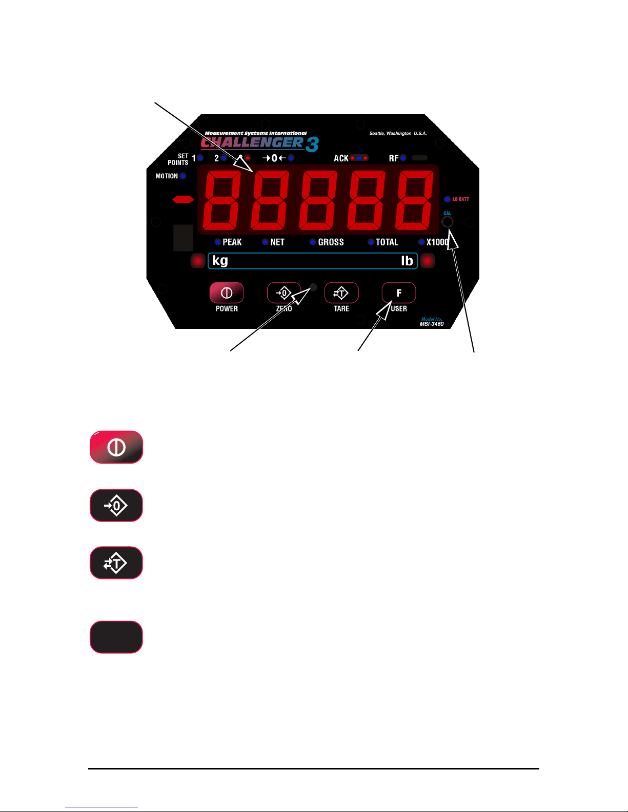
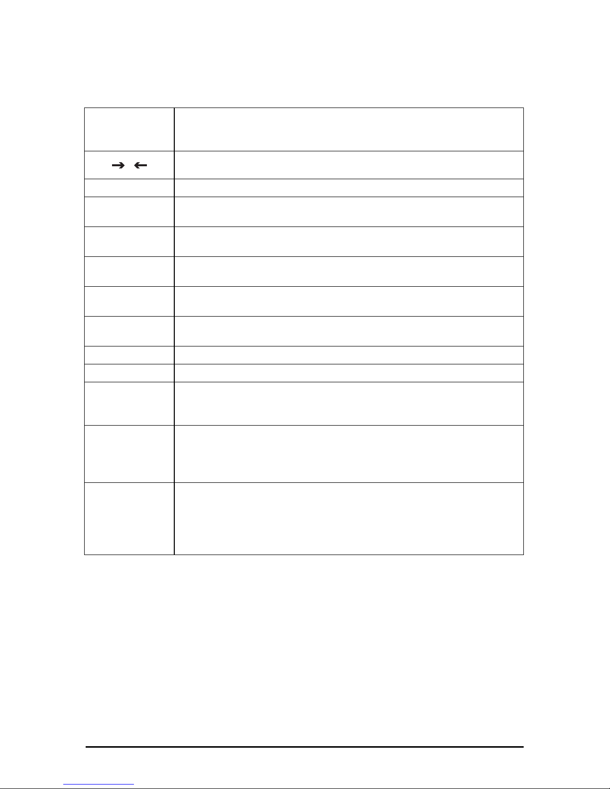
USER Programmable multifunction button for use as
TEST, TOTAL, UNIT, PEAK, NET/GROSS, VIEW TOTAL, LEARN
(for RF Remote Control), HI-RES
CAL Front panel calibration switch (located behind wire sealable screw)
Initiates full digital calibration procedure
Auto Zero
Maintenance
Standard, can be disabled internally
Auto-Off Mode Prolongs battery life by turning POWER off after 15, 30, 45 or 60
minutes (operator determined) of no scale activity
Auto-Sleep Mode Prolongs battery life by dimming LED display after 5, 15, or 30
minutes of no activity
Units kg, lb (other units available with custom calibrations)
Filtering Selectable: OFF, Low (LO), Medium (HI-1), High (HI-2)
Totalization Standard: Press button or automatic; TOTAL weight up to 99999 X
1000 kg or lb
Peak Uses unfiltered faster reading of A/D, (>220 readings per second)
Setpoints Three internal standard setpoints and three ultra bright LEDs on
front panel
Service Counter Two independent 32 bit registers; register 1 updated each time
weight exceeds 25% of capacity; register 2 updated each time
weight exceeds overload; when register 1 exceeds 16383 or
register 2 exceeds 1023, display reads “Cnt” for load cell counter;
Test function shows the two readings in order
Construction All of these features are housed in a single, low-profile, cast
aluminum housing consisting of three sections:
The front of the scale houses the display, controls and all
electronics
The center section contains the load cell, lifting eye and hook
The rear of the scale features a quick access battery compartment
Table 1-1. Specifications

Introduction 7
The MSI-3460 scale has a safe mechanical overload of 200%, and
an ultimate overload of 500%. Overloads greater than 500% may
result in structural failure and dropped loads. Dropped loads may
cause serious personal injury or death.
OPTIONS
Wireless Remote
Controler
50(15 m) typical range Light-of-Sight. Uses 418 MHz (USA)
handheld transmitter.
802.15.4 RF
Modem for
connectivity with
MSI-8000 RF
Remote Display
Integral 802.15.4 RF Modem for connectivity to Optional MSI-8000
RF Remote Display.
MSI-8000 RF
Remote Display
100(30 m) typical range line of sight. Uses 802.15.4, 2.4 GHz
transciever
WARNING
Table 1-1. Specifications

8 MSI-3460 Operator’s Manual
1.5 Features
• Designed to meet or exceed all U.S. and international standards.
• Typically 50 hours of weighing time utilizing automatic sleep mode.
• Automatic power off conserves battery life by sensing no activity after 15, 30, 45
or 60 minutes, determined by operator, and turns off power.
• Automatic Sleep Mode preserves battery life by dimming the LED display after
5, 15, or 30 minutes of no activity.
• Rugged construction throughout. Buttons are sealed and rated for over one
million operations.
• Precise high resolution (2500 division standard and up to 10,000 possible) 24 bit
A/D conversion coupled with advanced RISC micro controller provides world
class features and accuracy.
• Five large, 1.5 inch (38 mm) LED digits for clear weight readings from a
distance.
• Easy to maintain: full digital calibration assures reliable, repeatable
measurements. Can be calibrated without test weights using MSI R-Cal
technology.
• Selectable for kg/lb unless prohibited by LFT regulations.
• Automatic or manual weight totalization for loading operations.
• Easily customized for specialapplications.
• Hi speed PEAK mode for wire and rope stress analysis.
• Three setpoints can be set for any in-range weight for operator alerts or process
control.
• ScaleCore technology provides quick and easy software updates and calibration/
setup backup.
•Two service counters ensure load train safety by warning the user to perform a
load train safety check when the lift count gets high or the scale has been
overloaded repeatedly.
1.6 Options
Options which you may have ordered with your Challenger 3 may include the
following:
• RF remote controller
• RF modem for connectivity to MSI-8000 RF Remote Display
• MSI-8000 RF Display
• 85-265 VAC input power.
• Audible alarm (triggered by setpoint 1)
1.7 Unpacking
When unpacking the scale from the shipping container, ensure that all assembly parts
are accounted for. Check the scale for any visible damage and immediately report any
damage to your shipper. It is advisable to use the original shipping container when
shipping or transporting the Challenger 3.

Introduction 9
1.8 Assembly
Battery
Cotter
Load
Hook Clevis
Clevis
Figure 1-2. MSI-3460 Assembly
1. Slide hook clevis over load cell with open end of hook toward front of scale.
2. Align holes of clevis and load cell.
3. Slide the clevis pin through the clevis and load cell holes.
4. Lock clevis pin in place with cotter pin. Bend cotter pin.
WARNING
Scale will be unsafe for use if clevis pin is not properly secured with
the cotter pin.
5. Slide battery pack into battery compartment. The battery will automatically
engage with its connectors.
6. Secure battery pack by turning the two locking fasteners on access door
clockwise 1/4 turn.
7. The scale is now ready for use.

10 MSI-3460 Operator’s Manual
1.9 Ba tt e r y Pack
The MSI-3460 is powered by a six volt rechargeable battery. The battery door is part
of the battery pack.
Access Door Fastener Handle
Figure 1-3. Battery Pack Removal
To Remove the Battery Pack
1. Turn the two fasteners on the access door counter clockwise 1/4 turn,
2. Grasp handle and pull the battery pack straight out. The battery will
automatically disengage from its connectors.
The battery will operate for up to 100 hours (depending on LED brightness setting)
before requiring recharging. In order to conserve battery life, the scale includes an
automatic power off mode which senses operational status for no activity after 15, 30,
45, or 60 minutes, and turns the scale off. An additional battery saving feature is the
automatic sleep mode. This feature preserves battery life by dimming the display after
5, 15, or 30 minutes of no scale activity. Charging time for a completely discharged
battery is up to eight hours. A spare battery pack is recommended to keep the
Challenger 3 in continuous operation.
Note
To obtain maximum service life from your batteries they should be
stored between -4°F and 122°F (-20°C and +50°C). Stored batteries
should be recharged every three months. Battery is fully charged when
the status indicator is flashing.

Introduction 11
1.10 Battery Charger
1. Remove the battery from the scale.
2. Plug battery charger into an AC power receptacle. The input voltage is universal
from 115/230 VAC, 50/60 Hz. If the power input plug doesn’t match, contact
MSI for information on international plugs.
3. Slide the battery charger connector plate over the top of the battery until the
battery terminals mate with the charger connectors, as seen through the two
observation holes.
4. Approximately six to eight hours is required to recharge a fully discharged
battery. If a battery was deep discharged, more time might be required, but the
MSI-3460 prevents deep discharging. Partially discharged batteries will finish
the charge faster.
The charger is a three stage float charger that can be left on the battery indefinitely. It
has a dual color LED to indicate the charging state: RED- fast charge mode. GREEN-
charged or float charge.
Inside of charger
Observation
holes
Charger Connectors
Figure 1-4. Battery Charger
Note
To obtain maximum service life from your batteries, the manufacturer
suggests recharging after each 20 hours of use. Continuous deep
discharging will reduce maximum battery life cycle estimated at 2000
cycles.
A second battery is recommended to enable you to use your scale
continuously. Keep one on the charger while the other is in service.

12 MSI-3460 Operator’s Manual
2.0 Operation
2.1 Power
To turn on the power.
1. Press , the following will display in order:
• LED will light all segments at full brightness as a display test.
• Display brightness will change to the setting determined in the display menu.
• Software version number will display.
• The MSI-3460 is ready for use.
2.2 Zero
Sets the zero reading of the Scale. Use the ZERO key to take out small deviations in
zero when the scale is unloaded. See “TARE” for zeroing (Taring) package or pallet
weights.
1. Press
Note
The weight reading must be stable within the motion window for the
zero function to work.
The scale digits display 0 (or 0.0 or 0.00, etc).
The backup memory in the MSI-3460 stores the zero reading, and can
restore it even if the power fails.
Rules for Use:
• Works in GROSS mode or NET mode. Zeroing while in net mode will zero
the gross weight causing the display to show the negative tare value.
• The scale must be stable within the motion window. The scale will not zero
if the motion detect annunciator is on. The scale will “remember” that it has
a zero request for two seconds. If motion clears in that time, the scale will
zero.
• The scale will accept a zero setting over the full range of the scale (NTEP
and other Legal for Trade models may have a limited zero range). Zero
settings above 4% of full scale will subtract from the overall capacity of the
scale. For example if you zero out 100 lb. on a 1000 lb. scale the overall
capacity of the scale will reduce to 900 lb. plus the allowed over-range
amount.

Operation 13
2.3 Tare
Tare is typically used to zero out a known weight such as a packing container or pallet
and display the load in NET weight. A tare value is entered by pressing the TARE
key. The TARE function in the MSI-3460 is defined as a Tare-In, Tare-Out operation.
The first press of the TARE key stores the current weight as a tare value and then the
scale subtracts the tare value from the gross weight and changes the display to NET
mode. The next press of the TARE key will clear the tare value and revert the display
to GROSS mode.
To view the gross weight without clearing the tare value, program the USER key to
the function “NET/GROSS.” The RF remote control has a Net/Gross permanently
available.
To Tare and Display the Net Weight
1. Press
Note
The weight reading must be stable within the motion window for the
tare function to work.
The scale digits display 0 (or 0.0 or 0.00, etc) and the weight mode
changes to NET.
The backup memory in the
MSI-3460
stores the tare reading and can
restore it even if power fails.
To Clear the Tare and revert to Gross Weight
1. Press . The net annunciator will turn off and the gross annunciator will
turn on.
Tare - Rules for Use:
• Only positive gross weight readings can be tared.
• The motion annunciator must be off. The weight reading must be stable.
• Setting or changing the tare has no effect on the Gross zero setting.
• Taring will reduce the apparent over range of the scale. For example, taring a
100 lb container on a 1000 lb scale, the scale will overload at a net weight of
900 lb (1000-100) plus any additional allowed overload (usually ~4% or 9d).
• The scale stores the tare value in non-volatile memory and is restored when
power is cycled.

14 MSI-3460 Operator’s Manual
3.0 User Defined Function Keys
The following function descriptions are for optional user defined functions that are
programmed on the front panel USER key or the two function keys (F1 & F2) on the
RF remote control. The functions TOTAL, VIEW TOTAL, and NET/GROSS are
available full time on the RF remote control. To enable any of the USER key
functions, you must set up the USER keys following the procedures in Section 4.0.
TEST
The TEST function provides an LED test that lights all LEDs at once, next the SW
Model number followed by the software version number, the battery voltage, and then
performs a display test that counts from 00000 to 99999. Other internal tests are
performed and if any test fails, an error code will display. See Section 8.0 for a
description of all error codes. Press the USER key again within two seconds to enable
a single step through all the test functions. In the single step mode, use the USER key
to scroll through the available test functions and the TARE key to start or display the
individual tests. Use the ZERO key to exit individual tests. Use the ZERO key to exit
entirely from the TEST function.
CH3.5n – Challenger 3 software version number: Press TARE to see the software
version.
bAtt – Battery voltage: Press TARE to see the battery voltage.
d.tESt – Display test: Press TARE to have the display count up from 00000 to 99999.
C-CAL – Cal constant display: Press TAREto view the C-CAL value.
TOTAL
Note
The total mode must be programmed from the setup menus before
the USER key will function.
For accumulation of multiple weighments. The accumulator always uses the
displayed weight, so GROSS and NET readings can be added into the same TOTAL.
There are four modes of totalizing: manual and three auto modes. The manual mode
requires the TOTAL button be pressed with the weight on the scale. The weight will
be added to the previously accumulated value. This assures that a weight on the scale
is only added to the total once. Both the manual and three auto total modes require
that the weight on the scale return below 0.5% (relative to full scale) of GROSS
ZERO or NET ZERO before the next weighment can be added. Applied weight must
be ≥1% of full scale above GROSS ZERO or NET ZERO before it can be totaled.
MANUAL TOTAL
The USER key under the MANUAL TOTAL mode functions in this manner:
Weight is > 1% of Capacity and has not been totaled – Pressing the USERkey
will add the current weight to the TOTAL weight. The ACK LEDs blink to indicate
the weight was accepted. The TOTAL annunciator lights and the total weight is
displayed for five seconds and then the number of samples is displayed for two
seconds.
Current Weight has been totaled – Pressing the USER key will display the total
weight for five seconds (View Total) without changing the total value. The TOTAL
annunciator will light during the TOTAL weight display. After five seconds of total
weight display, the number of samples is displayed for two seconds.
Weight is <1% of Capacity – The USER key functions as “View Total” only and
functions as view total until the 1% threshold is exceeded to allow the next addition to
the total value.

User Defined Function Keys 15
AUTO TOTAL
The USER key under the AUTO TOTAL mode functions as Auto Total On / Auto
Total Off.
The auto mode has three variations which are programmed in the SETUP menu:
•AutoLoad – Any settled weight above the ‘Rise above’ threshold will be
automatically totaled. Then the scale must fall below the ‘Drop below’ threshold
before another total is allowed.
•AutoNorm – This mode takes the last settled weight to auto total with. The total
occurs only once the scale goes below the threshold. This allows the load to be
adjusted without a total occurring. Once the load is removed, the scale uses the
last settled reading for total.
•AutoHigh – Similar to the AutoNorm mode except the scale uses the highest
settled reading. Useful for loads that can’t be removed all at once.
View Total
The function key activates the total weight display followed by the number of
samples. While the display is showing the total, total is cleared by pressing ZERO.
Net / Gross
Switches the display between net and gross modes. Net weight is defined as gross
weight minus a tare weight.
To switch between net mode and gross mode:
1. Press the USER key (Setup to the Net/Gross function).
2. The NET/GROSSkey will only function if a tare value has been established.
3. Switching back to gross mode from net mode will not clear the tare value. This
allows the operator to use the gross mode temporarily without having to re-
establish the tare value. Only clearing the tare or setting a new tare will change
the tare value held before switching into gross mode.
OIML LFT units only: The NET/GROSS key is temporary action only. The gross
weight is displayed for two seconds and then the display returns to the net mode. The
only way to return to permanent gross readings is to clear the tare (see clear tare
procedure).
PRINT
If print option is installed this menu choice will appear. The setup of the print function
is covered in the option manual.
LEARN
Used for programming the RF remote control. This function is detailed in Section 6.0.
PEAK HOLD
Peak hold will only update the display when a higher peak weight reading is
established. The peak hold function uses a high speed mode of the A/D converter
allowing it to capture transient weights at a far higher rate than typical scales. Peak
hold is cleared and re-enabled with the USER key.
PEAK HOLD is not available on NTEP or OIML certified Legal for Trade scales.
UNIT
The function key will switch the weight units between pounds and kilograms.
UNIT switching is not available on OIML certified Legal for Trade scales.

16 MSI-3460 Operator’s Manual
4.0 Configuration
4.1 Menu Map
)YQF
IYQF
DII
6/((3
GLVSO
6W3W
6W3W
6W3W
WRWDO
ILOWU
81L7
2))
WHVW
WRWDO
YWWO
1(W U
/HDUQ
3+OG
8QLW
2II
II
/R
+L
+L
DYWR
/R
/R
+L
+L
kg lb
2))
UHDW
/(66
Number Entry
Off
Test Display
*Total
*View Total
*Net/Gross
Remote Learn
**Units
***Peak Hold
USER KEY
FUNCTIONS
TOTAL MODE
Total Off (default)
Total On Manual
Autototal on Load
Autototal Last
Autototal on High Load
2II
WWO2Q
$/R$'
$/$6W
$+L K
USER
F
Function User Key 1
Function User Key 2
Auto Off Time
Sleep Mode
Display Intensity
Set Point 1
Set Point 2
Set Point 3
Total Mode
**Weight Filter
***Weight Units
SETUP MENU
Disabled(default)
15 minutes
30 minutes
45 minutes
1 hour
AUTO OFF TIME
OFF (disabled)
Low (default)
High Filter
Very High Filter
SOFTWARE FILTER
LED DISPLAY INTENSITY
Auto by Light Sensor (default)
Dim(longest battery life)
Medium Dim
Medium Bright
Maximum Bright
POWER
*
Function always available on the RF Remote
**
Function not available or non-functional in OIML R76 & 1Unit modes
***
Function not available or non-functional in OIML R76 or NTEP HB44 modes
With the Power off, hold
down the USER key, then
turn the Power on.
Or press POWER and USER
simultaneously
USER
F
TARE
ENTER / SELECT
POWER
EXIT and Cancel Changes
ZERO
EXIT and SAVE
USER
FSCROLLs through
Menu Choices
Set Point Off (default)
Greater Than
Less Than
Totals on first stable load
Totals the last stable load before zero return
Totals the highest stable load
Totals by pressing the USER key
Autototal Last and Autototal High total when the scale is unloaded.
F2 is only on the RF Remote
2))
SLEEP DELAY
Off, Sleep disabled
5 Minutes
(default)
15 Minutes
30 Minutes
(default)
Figure 4-1. Setup Menu Map
Table of contents
Other MSI Scale manuals