A&D SB-30 User manual

S
SB
B
S
Se
er
ri
ie
es
s
D
Di
ig
gi
it
ta
al
l
B
Be
en
nc
ch
h
S
Sc
ca
al
le
es
s
Instruction Manual
Revision 1.3 April 5, 2000
SB-30
SB-70
SB-150

2 Revision 04/2001
ATTENTION:
To extend the life of your digital scale, do not drop items to be weighed onto the
platform or overload the scale beyond its rated capacity. Shock-loading and
overloading may damage the load cell and void the warranty.
Table of Contents
Introduction ..................................................................................................................................2
Installation and Wiring..................................................................................................................3
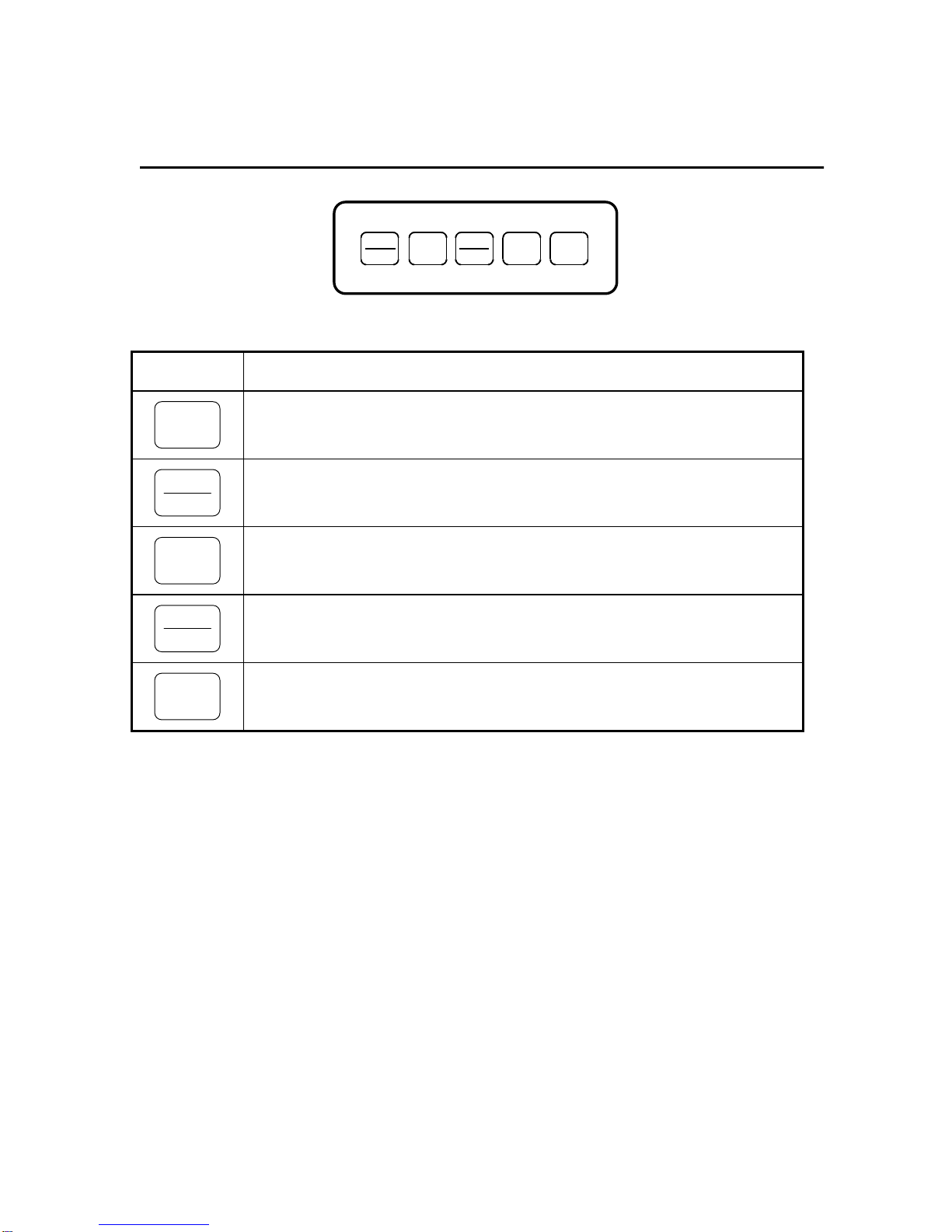
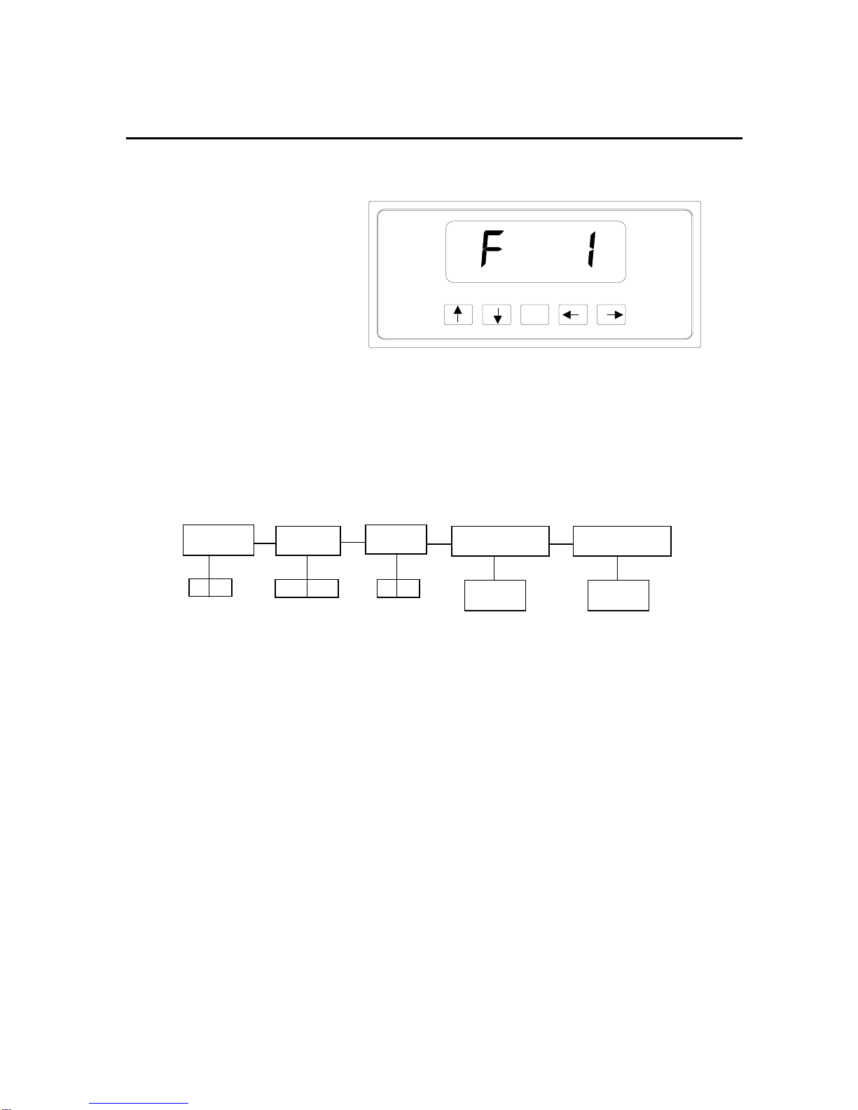
Display Overview..........................................................................................................................4
Keyboard Functions .....................................................................................................................5
User Menu Mode..........................................................................................................................6
Setup Menu Mode........................................................................................................................7
Calibration ....................................................................................................................................9
APPENDIX A: Specifications .......................................................................................................11
APPENDIX B: Troubleshooting the Serial Port ............................................................................12
APPENDIX C: Displayed Error Codes .........................................................................................13
APPENDIX D: Warranty and Service Information........................................................................14
Introduction
The SB-30/70/150 Digital Bench Scales are
compact bench scales with display and five
function keyboard. It is available in 30 lb (15
kg), 70 lb (30 kg) and 150 lb (70 kg) capaci-
ties. It comes standard with a bright LED
screen for easy readout, a removable stain-
less steel platform, and an RS-232C serial
communication port.
These scales can be configured to display
their divisions in two separate modes – non-
NTEP mode and NTEP mode. The scale is
shipped from the factory configured in NTEP
mode. The NTEP mode is supplied for
scales which need to comply with Handbook
44 requirements. To re-configure the scale,
please refer to the “Setup Menu Mode” sec-
tion of the manual.
SB-30/70/150 use full duplex RS-232C serial
format for communication with personal
computers or remote displays. Units can
transmit data on demand or continuously in
several popular data protocols.
Each scale’s serial communication parame-
ters are altered through the User menu The
“User Menu Mode” section of the manual
explains how to use the five front panel keys
to maneuver and save settings in this menu.

SB-30/70/150 Operation Manual 3
Installation and Wiring
The scale’s back panel comes equipped with
a female DSUB-9 connector for the RS-232
serial port, a jack for DC power input, a cali-
bration switch, a remote display connector
(SB-30 & SB-70 only) and an ON/OFF rocker
switch. To install the scale, simply plug the
enclosed AC Wall Adapter into the scale’s DC
power jack first, then into an AC outlet (115
VAC only). For SB-30 and SB-70 scales, plug
in the remote display/keyboard unit. Finally,
turn the rocker switch to the ON (“1”) position.
The scale is now ready for use.
ON/OFF
SWITCH
DC POWER
JACK
RS-232
PORT REMOTE
DISPLAY
ID TAG
CALIBRATION
SWITCH COVER (SB-30 & 70 ONLY)
CONNECTOR
SB-30/70/150 Back Panel
The female 9-Pin RS-232
connector is used to interface
to a PC. Shown at right are
the pin assignments for the
connector.
Pin No. Pin Name
2Receive Data
3Transmit Data
5Signal Ground
235
9-pin RS-232 connector (female)
Shown at right is the suggested cable diagram
for direct connection to a PC. Or, you can order
the optional pre-wired NMC-1 Null Modem Ca-
ble
TO SCALE TO PC
2 RXDRXD 2
TXD 3
S. GND 5
3TXD
5 S. GND
6 DSR
4DTR
8 CTS
DSUB9 DSUB9
FIGURE 1. Cable Diagram for Scale to IBM PC

4 Revision 04/2001
Display Overview
ZERO
TARE
NET
GROSS lb
STABLE
kg
SB-30/70/150 Display Area
ANNUNCIATOR MEANING
ZERO Better known as the “Center of Zero” annunciator, this light is active whenever the
displayed weight is within ± 0.25 divisions of true zero.
NET Indicates that the scale is displaying net weight.
GROSS Indicates that the scale is displaying gross weight.
TARE Indicates that the tare weight in the system was established by means of the push
button method.
lb and kg Indicates the unit of the displayed weight.
STABLE This light indicates that the scale is in equilibrium.

SB-30/70/150 Operation Manual 5
Keyboard Functions
NET
GROSS
ZERO
lb
kg TARE PRINT
SB-30/70/150 Series Keyboard
KEY FUNCTION
ZERO
Sets scale to display "0" only when a) in Gross mode, b) not in overload and c) not in
motion.
NET
GROSS
Toggles between Gross and Net weight display if a tare has been established.
TARE
Used to establish the weight on the platform as the tare weight. You cannot establish
zero or negative gross weight as a tare. Also, the scale must not be in motion or in
overload.
lb
kg
Toggles between lb and kg units if enabled in the User (“A”) Menu.
PRINT
Sends "Print" data to serial port if scale is not in motion or in overload.

6 Revision 04/2001
User Menu Mode
SB-30/70/150 includes a User menu which contains the scale's serial communication parameters.
It consists of 5 separate menu selections, each also with its own sub-menu of choices.
To change a listed parameter, you must first enter the User Menu mode. Once there, four of the
front panel keys become directional navigators to move around in the menus, and one key is used
to save or SET the selections.
To place the unit in User menu mode:
1. Turn the power off to the unit.
2. While holding down the lb/kg
key, turn the power back on.
3. When the display shows "A1",
the unit is in User Menu mode,
and you can release the lb/kg
key. Shown at right are the direc-
tional and SET key assignments SET
USER MENU CHART
A1
Baud Rate
1200 2400 4800 9600
A2
Data Bits, Parity
8n 7O 7E
A3
Transmission Mode
Cd
A4
Serial Data Format
A5
Enable lb/kg Key
01
012 345
7n 6
To place the unit back into the Normal Operating mode:
1. Turn off the scale. Turn the scale back on without pressing any keys.
2. The display will go through a digit check, then settle into Normal Operating mode. All front panel
keys will now return to their normal mode of operation.

SB-30/70/150 Operation Manual 7
User Menu Mode / Continued
USER MENU DESCRIPTIONS
NAME/CODE DESCRIPTION CODE/VALUE
A1
Baud Rate
Selects the baud rate for data transmission through the serial port. 1200 2400√
√√
√
4800 9600
A2
Data Bits and
Parity
Selects the number of data bits and parity of serial transmission.
"8n" = 8 data bits with no parity bit and one stop bit
"7O" = 7 data bits with odd parity bit and one stop bit
"7E" = 7 data bits with even parity bit and one stop bit
"7n" = 7 data bits with no parity bit and two stop bits
8n√
√√
√
7O
7E
7n
A3
Mode of Serial
Transmission
Selects when data will be sent out of the serial port to a printer or
computer:
"C" = Continuous mode; send data continuously
"d" = Demand mode; send data when a PRINT command is issued
from the printer, computer, or scale.
C
d√
√√
√
A4
Serial Data
Format
Selects the data format to be transmitted via the serial port to a
printer or computer.
"0" = Consolidated Controls Format
"1" = Toledo 8213 Format "2" = A&D/NCI/CAS Format
"3" = Transcell Technology Format
“4” = Detecto ASD Format “5” = Triner Format
"6" = Fairbanks 70-2453-4 Format
0
1
2
3√
√√
√
4
5
6
A5
Disable the
lb/kg Key
Allows the lb/kg key to be disabled so that an operator cannot acci-
dentally press the key and change the displayed units.
"0" = Disable the lb/kg key "1" = Enable the lb/kg key
0
1√
√√
√
Setup Menu Mode
SB-30/70/150 scale include a Setup menu which determines the scale’s display mode, allows
scale calibration and also contains the scale's adjustable functional parameters. It consists of 5
separate menu selections, each also with its own sub-menu of choices.
To change a listed parameter, you must first enter the Setup Menu mode. Once there, four of the
front panel keys become directional navigators to move around in the menus, and one key is used
to save or SET the selections.

8 Revision 04/2001
Setup Menu Mode / Continued
To place the unit in Setup menu mode:
1. Turn the power off to the unit.
2. Locate the calibration switch on
the scale’s back panel and toggle
to the opposite position.
3. While holding down both the
ZERO and PRINT keys, turn the
power back on.
4. When the display shows "F1",
the unit is in Setup Menu mode,
and you can release the two
keys. Shown at right are the di-
rectional and SET key assign-
ments
SET
SETUP MENU CHART
F1
Display Mode
F6
Zero Range
F9
Calib. Unit.
01
F11
Display Check
F12
Calibration
Press ZERO
key to begin
Press ZERO
key to begin
01 100% 1.9%
To place the unit back into the Normal Operating mode:
1. With the scale on or off, toggle the Calibration Switch back to its original position. Turn the scale
back on without pressing any keys.
2. The display will go through a digit check, then settle into Normal Operating mode. All front panel
keys will now return to their normal mode of operation.
3. There is an F13 sub-menu present that is for FACTORY USE ONLY!

SB-30/70/150 Operation Manual 9
Setup Menu Mode / Continued
SETUP MENU DESCRIPTIONS
NAME/CODE DESCRIPTION CODE/VALUE
F1
Display Mode
Selects display mode for the scale.
"0" = Non-NTEP mode
"1" = NTEP mode
0
1√
√√
√
F6
Zero Range
Selects the range within which the scale may be zeroed. Note that
the scale must be in standstill to zero the scale.
100%√
√√
√
1.9%
F9
Calib. Unit
Selects the primary base unit to be used in the calibration process.
Also the default unit for normal operation.
"0" = primary unit is lb. "1" = primary unit is in kg.
0√
√√
√
1
F11
Display Check
Actuates the function which illuminates all digit segments, decimal
points, and LCD annunciators in a test sequence. Pressing the
ZERO key to scroll down one level begins the test sequence.
Press ZERO key
to begin sequence
F12
Calibration
Places scale into the calibration routine. Scrolling down with the
ZERO key one level begins the procedure.
Press ZERO key
to begin sequence
F13
Factory Reset
This sub-menu will reset all parameters in the “F” and “A” menus to
the default settings. USE WITH CAUTION!!!!!
Press the ZERO
key twice to exe-
cute.
Calibration
ON/OFF
SWITCH
DC POWER
JACK
RS-232
PORT REMOTE
DISPLAY
ID TAG
CALIBRATION
SWITCH COVER
CONNECTOR
(SB-30 & 70 ONLY)
CALIBRATION MODE KEY FUNCTIONS
ZERO GROSS
NET TARE PRINT
SET
lb
kg
The scale can be calibrated by following the procedure shown below. The minimum test weight
and the recommended test weight depends on the scale’s capacity.
For the SB-30, the minimum test weight is 0.3 lb (0.15 kg) , and the recommended test weight is
20 lb (10 kg). For the SB-70, the minimum test weight is 0.7 lb (0.35 kg) , and the recommended
test weight is 47 lb (23 kg). For the SB-150, the minimum test weight is 1.5 lb (0.7 kg) , and the
recommended test weight is 100 lb (50 kg).

10 Revision 04/2001
Calibration / Continued
To calibrate the scale:
1. If you are already in Setup Menu Mode, scroll to “F 12” and press the ZERO key. Otherwise,
turn the scale off and set the Calibration Switch on the back panel to the opposite position.
Turn the unit back on.
The message "C 0" appears on the display briefly, followed by a value which remains on the
screen. Allow a 20 minute warm-up period for the load cell and other electronics to become
thermally stable.
2. Press
ZERO to zero the value, then press the NET/GROSS key to save the zero point value.
3. The display will momentarily prompt "C 1" for the span calibration, followed by "0.00" with one
digit flashing. Place the test weight on the platform.
4. Use the four directional keys to adjust the displayed value to the actual test weight value in
pounds. Increase the flashing digit by pressing the lb/kg key. Decrease the flashing digit by
pressing the ZERO key. The position of the flashing digit may be changed by pressing the
PRINT key or the TARE key.
5. After setting the exact value, press the NET/GROSS key to save the value.
6. If the calibration was successful, the display will show "ECAL" momentarily, then freeze. Exit
the Calibration mode and enter the Normal Operating Mode by positioning the Calibration
Switch back to its original position.
7. If the calibration was not successful, one of the error messages below will appear. Take the
indicated action to correct the problem, then perform a new calibration.
"Err0" - The calibration test weight or the adjusted keyed-in weight is larger than full scale.
Change the calibration test weight or check the keyed-in weight.
"Err1" - The calibration test weight or the adjusted keyed-in weight is smaller than 1% of full
scale. Change the calibration test weight or check the keyed-in weight.
"Err2" - Check keyed-in weight with the actual weight placed on platform.
To place the unit back into the Normal Operating mode:
1. Toggle the Calibration Switch back to its original position.
2. The display will go through a digit check, then settle into Normal Operating mode. All front
panel keys will now return to their normal mode of operation.

SB-30/70/150 Operation Manual 11
APPENDIX A: Specifications
MODEL Non Legal-for-trade Capacity
SB-30 0 - 5 x 0.005 lb (0 - 2 x 0.002 kg)
5 - 30 x 0.02 lb (2 - 15 x 0.01 kg)
Legal-for-trade Capacity
SB-70 0 - 5 x 0.005 lb (0 - 2 x 0.002 kg)
5 - 70 x 0.02 lb (2 - 30 x 0.01 kg)
SB-150 0 - 5 x 0.01 lb (0 - 2 x 0.005 kg)
5 - 70 x 0.02 lb (2 - 30 x 0.01 kg)
70 - 150 x 0.05 lb (30 - 70 x 0.02 kg)
0 - 30 x 0.01 lb (0 - 15 x 0.005 kg)
0 - 70 x 0.05 lb (0 - 30 x 0.02 kg)
0 - 150 x 0.05 lb (0 - 70 x 0.02 kg)
CONSTRUCTION:
Base: Steel and ABS
Platform: Stainless Steel
Feet: Non-skid Hard Rubber
DISPLAY:
6 Digit, 0.6", 7-Segment Green LED
OVER CAPACITY ANNUNCIATION:
102% of Full Scale Capacity
OPERATING TEMPERATURE RANGE:
32°F to 104°F (0°C to 40°C)
PLATTER SIZE:
SB-30/70: 10” x 13”
SB-150: 13” x 13”
POWER SOURCE:
AC Adapter, 12VDC, 500mA
WEIGHT:
Net Weight: 24.3 lb (11 kg)
Shipping Weight: 27.8 lb (12.6 kg)
PHYSICAL DIMENSIONS
13.0 in [330.2 mm]
4.4 in [112 mm]
ON/OFF
SWITCH
DC POWER
JACK
RS-232
PORT REMOTE
DISPLAY
ID TAG
CALIBRATION
SWITCH COVER
13.0 in [330.2 mm]
SB-150 Only
10.2 in [258.0 mm]
SB-30/70
CONNECTOR
(SB-30 & 70 ONLY)

12 Revision 04/2001
APPENDIX B: Troubleshooting the Serial Port
The scale’s serial port operation can be verified by following the procedure below. This procedure
makes use of HyperTerminal - a serial port communication program bundled with Windows 95
and Windows 98 operating systems. A HyperTerminal configuration file is available on the Tran-
scell website.
A comprehensive summary of the various Serial Data Formats (SDF’s) can be found in the SB
Series Service Manual.
To test the scale’s serial port for proper operation:
1. Connect the NMC-1 Null Modem Cable or equivalent between the scale and your PC. Make
sure to note which communication port (i.e. COM1, COM2) you are using on the PC.
2. On the scale, select the desired setting in the User Menu, including baud rate (A1), Data Bits
and Parity (A2), mode (A3), and serial data format (A4). Note that all Transcell scales have a
fixed parameter of one (1) stop bit.
3. On your PC, run HyperTerminal. Select the proper settings for the following using the scale’s
settings:
Baud Rate
Data Bits
Parity
Stop Bits = 1
4. Enable the CAPS LOCK key on your PC.
5. This test verifies that the scale is transmitting properly. If the scale is set to Demand mode,
pressing the PRINT key on the scale should echo the weight readout on the PC screen. If the
Continuous mode has been selected on the scale, the PC screen will overrun with weight in-
formation.
NOTE: The TOLEDO, A&D/NCI/CAS, FAIRBANKS and TRINER formats do not support a Con-
tinuous mode.
6. This test verifies that the scale is receiving properly. Use the table below to determine the
valid commands for your serial data format setting. For example the ‘P’ command is exe-
cuted by pressing the capital “P” key on your PC keyboard. Unless otherwise specified, you
do not need to press the ENTER key on your PC.
NOTE1: If the scale is set to Continuous mode, the print commands will be ignored.
NOTE2: If the scale is in motion, the print commands will be ignored for most SDF’s.
FUNCTION FORMAT(S) COMMAND
Print the weight CONSOLIDATED & TRANSCELL ‘P’
TOLEDO ‘W’
A&D/NCI/CAS & TRINER ‘W’ + <ENTER>
DETECTO ‘~’
FAIRBANKS <ENTER>

SB-30/70/150 Operation Manual 13
APPENDIX C: Displayed Error Codes
CODE MODE MEANING / POSSIBLE SOLUTION
Normal Operating Mode A weight greater than 102% of the scale’s capacity has
been applied to the scale. Remove the weight from the
platter. Try re-calibrating the scale if this doesn’t solve the
problem. Otherwise, possible load cell damage due to
overloading.
_ _ _ _ _ _ Normal Operating Mode Underrange condition. Platter has been removed. Re-install
platter. Try re-calibrating the scale if this doesn’t solve the
problem. Otherwise, possible load cell damage due to
shock loading.
– HI – Warmup Mode The scale has been turned on with a weight already present
on the platter. Remove the weight and then press the ZERO
key if necessary. Try re-calibrating the scale if this doesn’t
solve the problem. Otherwise, possible load cell damage
due to overloading.
– LO – Warmup Mode The scale has been turned on without the platter installed.
Install the platter and then press the ZERO key if neces-
sary. Try re-calibrating the scale if this doesn’t solve the
problem. Otherwise, possible load cell damage due to
shock loading.
Err 0 Calibration Mode Keyed-in weight value in Calibration Mode is less than 1%
of the scale’s capacity. Use a larger test weight or re-adjust
value.
Err 1 Calibration Mode Keyed-in weight value in Calibration Mode is larger than the
scale’s capacity. Use a smaller test weight or re-adjust
value.
Err 2 Calibration Mode Internal resolution is not high enough to process keyed-in
weight value in Calibration Mode. Verify test weight and
value.
Err 3 All Modes Diagnostics check error - EEPROM Read
Err 4 All Modes Diagnostics check error - EEPROM Write

14 Revision 04/2001
APPENDIX D: Warranty and Service Information
Seller warrants that each SB-30/70/150 will conform to written specifications, drawings, and
other descriptions made by the manufacturer, including any modifications thereof. Seller
warrants the goods against faulty workmanship and defective materials. If any goods fail to
conform to these warranties, Seller will, as its sole and exclusive liability hereunder, repair or
replace such goods if they are returned within the following warranty period: Two (2) years
from date of shipment. This warranty is made upon the express condition that:
1) Buyer notifies Seller of such non-conformity with detailed explanation of alleged deficiencies.
2) Product should not be returned without prior notice to Seller.
3) Other than setup functions & calibration, such goods have not been modified, altered, or
changed by any person other than the Seller or its duly authorized repair agents.
4) Examination of such goods by Seller discloses that the nonconformity actually exists and was
not caused by accident, misuse, neglect, alteration, improper installation improper or un-
authorized repair, or improper testing.
5) Seller will have a reasonable time to repair or replace such goods.
THESE WARRANTIES EXCLUDE ALL OTHER WARRANTIES, EXPRESS OR IMPLIED, ORAL OR WRIT-
TEN, INCLUDING WITHOUT LIMITATION WARRANTIES OF MERCHANTABILITY OR FITNESS FOR A
PARTICULAR PURPOSE. SELLER WILL NOT IN ANY EVENT BE LIABLE FOR INCIDENTAL OR CON-
SEQUENTIAL DAMAGES. IN ACCEPTING THIS WARRANTY, THE PURCHASER OR BUYER AGREES
TO WAIVE ANY AND ALL OTHER CLAIMS FOR RIGHT TO WARRANTY FROM A&D WEIGHING.
SHOULD THE SELLER BE OTHER THAN A&D WEIGHING, BUYER AGREES TO LOOK ONLY TO THE
SELLER FOR WARRANTY CLAIM OR CLAIMS.
No other terms, conditions, understanding, or agreements purporting to modify the terms of this warranty
shall have any legal effect unless made in writing and signed by a corporate officer of the Seller.
1555 McCandless Drive, Milpitas, CA 95035 •Tel: (800) 726-3364 / (408) 263-5333 •Fax: (408) 263-0119
Fax-on-Demand: (800) 726-7099, press 2 •Email: andweighing.com •Web: www.andweighing.com
This manual suits for next models
2
Table of contents
Other A&D Scale manuals
Popular Scale manuals by other brands

Silvercrest
Silvercrest SPWD 180 F1 Operating instructions and safety instructions

SRScales
SRScales SR416i-KG Operating and service manual

TScale
TScale s29 series Technical manual

TScale
TScale DR Series Technical guide

Silvercrest
Silvercrest 94301 Operation and safety notes

Proficook
Proficook PC-KW 1061 instruction manual

Concept2
Concept2 VO3000 manual

essentiel b
essentiel b EBC 10V user guide

Excell
Excell ELW Max user manual

parktool
parktool DS-2 quick start guide

Silvercrest
Silvercrest SBF 75 Operation and safety notes

Cambridge Scale Works, Inc.
Cambridge Scale Works, Inc. SS660-PT-OB Installation, Set-Up and Operation Manual