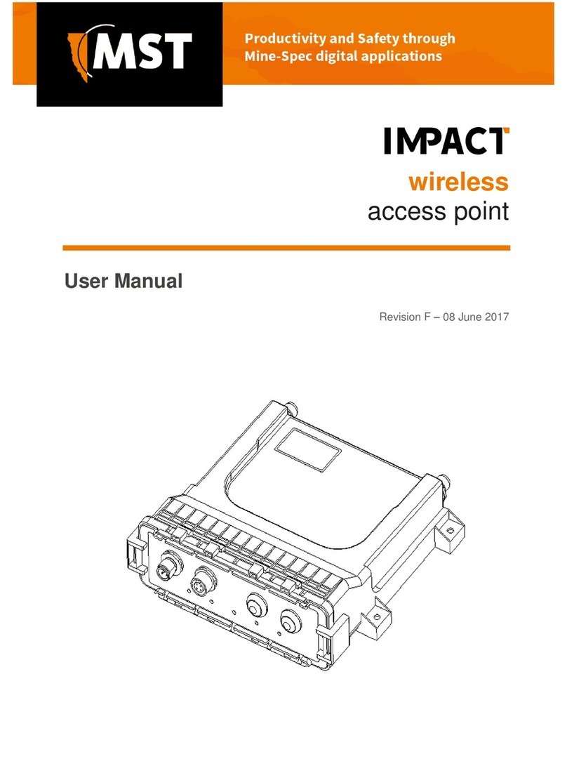
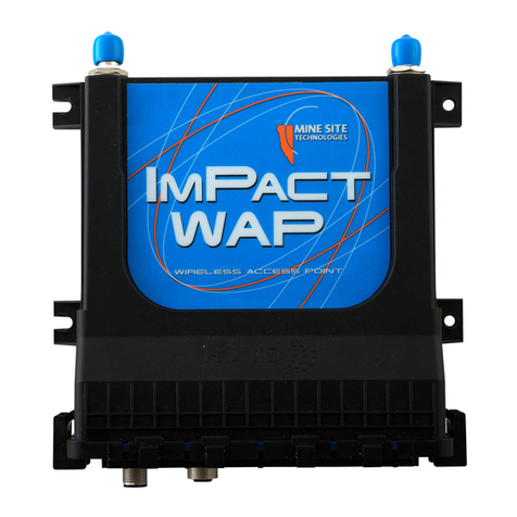
MST ImPact WAP User manual

Wireless Access Point
User Manual
Revision B


Contents
Revision History............................................................................................................................................5
Contact Information.......................................................................................................................................7
About This Manual........................................................................................................................................9
Chapter 1: Introduction...........................................................................11
1.1 Hardware Overview...................................................................................................................12
1.2 System Layout ..........................................................................................................................13
1.3 Connectivity...............................................................................................................................14
1.3.1 Ethernet Port...............................................................................................................14
1.3.2 Wireless Radio............................................................................................................14
Chapter 2: Installation..............................................................................15
2.1 Pre-installation Planning............................................................................................................16
2.2 WAP Mounting..........................................................................................................................16
2.3 Antenna Mounting Options.......................................................................................................17
2.4 Examples of WAP Installation Schemes....................................................................................18
2.4.1 Installation on Straight Drive.....................................................................................18
2.4.2 Wi-Fi Hotspot Installation..........................................................................................19
2.5 Ethernet Cable...........................................................................................................................20
2.6 Coaxial cable.............................................................................................................................22
Chapter 3: Conguration Using the Web Interface ..............................25
3.1 Logging onto the Web Browser Interface..................................................................................26
3.2 Conguration screen..................................................................................................................26
3.3 Status Tab...................................................................................................................................27
3.3.1 Obtaining Device Information....................................................................................27
3.3.2 Wireless Client Information........................................................................................28
3.3.3 Viewing System Logs.................................................................................................29
3.3.4 Viewing Network Trafc Statistics............................................................................30
3.3.5 Viewing Tracking Information...................................................................................31
3.3.6 Viewing Recent Tag Reports......................................................................................32
3.4 Tools Tab...................................................................................................................................33
3.4.1 Conguring Administrator and User Settings............................................................33
3.4.2 Setting the Time..........................................................................................................35
3.4.3 Rebooting or Restoring the Network Device..............................................................37
3.4.4 Upgrading Firmware...................................................................................................37
3.5 Settings Tab...............................................................................................................................40
3.5.1 Managing Automatic TFTP Conguration................................................................40
3.5.2 Conguring SNMP Settings.......................................................................................40
3.5.3 Setting Up the LAN....................................................................................................41
Wireless Access Point User Manual3Revision B

3.5.4 Conguring Wireless Radio.......................................................................................42
3.5.5 Conguring Wireless Networks.................................................................................45
3.5.6 Conguring EAP (Extensible Authentication Protocol)............................................47
3.5.7 WDS (Wireless Distribution System) settings............................................................49
3.5.8 Conguring Asset Tracking and Location Based Services........................................49
3.5.9 Enabling the MAC Address Filter..............................................................................51
3.5.10 Dening VLANs......................................................................................................52
3.5.11 Assigning VLANs to Wireless Networks.................................................................53
Chapter 4: Centralised Conguration Management ............................55
4.1 Device Management Overview.................................................................................................56
4.1.1 Site Conguration.......................................................................................................56
4.1.2 AP Cong Templates..................................................................................................56
4.1.3 Access Point...............................................................................................................58
4.2 TFTP Server Overview..............................................................................................................60
4.3 TFTP Parameters.......................................................................................................................61
Appendix A: Troubleshooting Guide.......................................................63
Appendix B: Using the Console Port to Supply Power..........................65
Appendix C: Ethernet Cable Specications...........................................67
Appendix D: Connecting a PC to an ImPact Network Device..............69
Appendix E: Device Discovery.................................................................73
Appendix F: Time Zone Indices and Offsets .........................................75
Appendix G: Repairs and Maintenance..................................................79
Appendix H: Acronyms............................................................................81
Appendix I: Hardware Warranty and Software License Agreement...83
I.1 Hardware Warranty....................................................................................................................83
I.2 Software End User License Agreement.....................................................................................83
Appendix J: Specications.......................................................................87
Revision B4Wireless Access Point User Manual

Revision History
DateChangeRevision
September 2011User Manual for WAP hardware Rev C and
rmware 2.22.4
A
December 2012Updated for rmware 2.24.2B
Copyright ©2012 Mine Site Technologies Pty Ltd. All rights reserved. Mine Site Technologies Pty Ltd
reserves the right to make changes to specications and information in this manual without prior notice.
Mine Site Technologies Pty Ltd accepts no responsibility for any errors or omissions contained in this
manual.
Wireless Access Point User Manual5Revision B


Contact Information
AUSTRALIA - Sydney
113 Wicks Road
North Ryde NSW 2113 AUSTRALIA
Tel: +61 2 9491 6500
CANADA - Sudbury
1085 Kelly Lake Road
Sudbury Ontario P3E 5P5 CANADA
Tel: +1 705-675 7468
CHINA - Hangzhou
4F, Building 1
1413 Moganshan Road
Hangzhou CHINA 310011
Tel: +86 571 85803320x206
UNITED STATES - Denver
13301 W 43rd Drive
Golden Colorado 80403 USA
Tel: +1 303-951 0570
GERMANY - Berlin
Mine Site Technologies (GmbH)
Uhlandstr. 20-25
10623 Berlin
GERMANY
Tel: +49 30 8861 4511
Wireless Access Point User Manual7Revision B


About This Manual
This manual describes features and functions of the ImPact Wireless Access Point (WAP) hardware. It
provides information about hardware, installation, conguration and how to troubleshoot any issues. You
will nd it easier to use the manual if you are familiar with networking systems and have an understanding
of electronics in a network environment.
Conventions used in the manual
This publication uses the following conventions to highlight and convey information:
• Text that requires input from an operator is boldfaced.
• Operator interface screen control names are boldfaced.
• Keyboard input keys are CAPITALISED.
Icons
Icons are used in the manual to highlight specic information as shown the table below.
DescriptionIcon
The Note icon indicates important information or references to the
user.
Note:
The Important icon contains information to prevent damage to the
product and injury to the user.
Important:
The Caution icon indicates to stop and pay attention or an action not
to be performed.
Caution:
Related Publications
ImPact Wireless Network Switch User Manual
Additional Support
For additional support please visit our website www.minesite.com.au.
Note: The information provided in this document ("Information") is presented in good faith and
believed to be correct as at the date of this document. MST makes no representations as to the
accuracy or completeness of the Information. The Information is supplied on the condition that the
recipient will make their own determination as to the suitability of the Information for their purposes
prior to use. Under no circumstances will MST be responsible for any damages whatsoever resulting
from the use of, or reliance upon, the Information.
Wireless Access Point User Manual9Revision B


Chapter
1
Introduction
This chapter presents the features and functions of ImPact Wireless
Access Point (WAP) and shows how it is integrated within a network.
Topics:
•Hardware Overview
Mine Site Technologies' ImPact WAP is a 802.11 b/g wireless access
point. It is used in conjunction with the ImPact Wireless Network
•System Layout
•Connectivity Switch, providing a wireless network for surface and hard rock mining
environments. The WAP forms part of the ImPact network
infrastructure where voice, tracking, video and process control
applications can be used to enhance mining safety and communications.
The WAP has the following features:
• 10/100 Ethernet port
• 802.11b/g wireless radio
• Rugged enclosure meeting IP66 standards
•AeroScout®Tag reading capability, allowing real time tracking of
assets and personnel
• Low power design, with a wide input voltage from 10-50VDC
•Simple Network Management Protocol (SNMP) support for remote
monitoring
• Wireless Distribution System (WDS) for wireless VLAN trunking
with other ImPact network devices.
For detailed specications on the WAP, refer to Specications on page
87.
Wireless Access Point User Manual11Revision B

1.1 Hardware Overview
The features and functions of the WAP are illustrated below.
FunctionDescriptionKey
Solid red indicates power is applied to the unit.Power indicator LED1
Revision B12Wireless Access Point User Manual
Introduction

FunctionDescriptionKey
Flashing red indicates normal operation.Status indicator LED2
Lit when the Ethernet link is established, and ashes when
data is transmitted or received.
Local Area Network (LAN)
indicator LED
3
Lit when the WLAN is active, and ashes when wireless
data is transmitted or received.
Wireless Local Area Network
(WLAN) indicator LED
4
Flashes when a Wi-Fi Tag is detected by the radio card.Data LED5
This LED has no function on the WAP.Auxiliary LED6
Ethernet port that receives power to the WAP (via 802.3af)
and transmits and receives network data.
Ethernet port (powered device)7
Mounting holes for attaching to a WAP mounting plate for
installation.
WAP mounting points8
Can be used for applying DC power to the unit if an 802.3af
power source is not available. Please refer to Using the
Console Serial port9
Console Port to Supply Power on page 65 for details on
how to apply power via this port.
RP-TNC jack for connecting an antenna.MAIN antenna port10
RP-TNC jack for connecting an antenna.AUX antenna port11
A protective cover when the antenna jack is not in use.RP-TNC antenna jack protective
cover
12
1.2 System Layout
The diagram below shows an example network layout in a mine incorporating WAPs. A mine will typically
deploy Wireless Network Switches (WNS, NS50 etc.) to form the main network infrastructure. WAPs
then connected and powered from the network switch using Power over Ethernet (PoE) to extend the
wireless network. They are positioned as network branches to improve coverage in conned areas such
as in refuge bays.
Wireless Access Point User Manual13Revision B
Introduction

1.3 Connectivity
The WAP has two types of network connections:
• Ethernet Port
• Wireless Radio
1.3.1 Ethernet Port
The WAP's Ethernet port is used for transferring data, and can also receive power from PoE enabled
switches. The WAP can operate over a wide voltage range of 10-50VDC, and is connected and powered
from the Network Switch, or using a PoE power supply.
Note: The Network Switch connected to the WAP needs to receive a minimum of 15VDC in order
to supply PoE power from its Ethernet Ports. Please consult your MST System Engineer in regards
to planning power distribution for your network.
1.3.2 Wireless Radio
Wireless connectivity is implemented using a Wireless Access Card (WAC), consisting of a wireless
network processor and an integrated mini PCI 802.11 b/g adapter.
The wireless network can be congured with up to four Service Set Identiers (SSIDs), each associated
with a different VLAN. This enables separation of applications such as voice, process control, video and
network management.
The wireless network settings can be congured through each device's web interface or by centralised
conguration management (using TFTP). For more information, see Centralised Conguration
Management on page 55.
Revision B14Wireless Access Point User Manual
Introduction

Chapter
2
Installation
This chapter describes the options for mounting and installation of
WAPs, antennas, and the connection of cables. Cable termination is
beyond the scope of this manual.
Topics:
•Pre-installation Planning
•WAP Mounting
Important: The electronic components in a WAP are designed
to be isolated from local electrical earth. This is known as
•Antenna Mounting Options
•Examples of WAP Installation
Schemes galvanic isolation and ensures there is no current passing between
grounds of different potential. In the event of a short circuit to
•Ethernet Cable earth, galvanic isolation prevents damage to devices in the
•Coaxial cable network as there are no loops for current to ow through.
Galvanic isolation must always be maintained, with antenna and
coaxial cable connections properly insulated.
Wireless Access Point User Manual15Revision B

2.1 Pre-installation Planning
A site inspection of a mine is conducted by an MST System Engineer to determine network requirements
and design before installation.
The following factors affect the conguration of the network required:
• Wireless coverage requirements of the mine
• Quantity and type of wireless client devices connected to the network
• Wired client devices connected to the network and their location
• Interconnection to the mines existing corporate network
• Policies for network protocols between networks
• Cabling requirements
• Antenna types to use with each unit and mounting method for each antenna
• Mounting location and installation method for each network device.
For more information about considerations in system design, refer to the user manual for your ImPact
Wireless Network Switch.
2.2 WAP Mounting
A WAP can be attached to a mounting plate with M6 nuts and bolts. The mounting plate allows various
mounting options as shown in the following table.
IllustrationDescriptionMounting
Option
The mounting plate has a
25mm hole for mounting
to a rock bolt in a mine.
The mounting plate is
secured to the rock bolt
with a 25mm nut.
Mounting the
WAP to a
rock bolt.
The four corner mounting
points on the mounting
plate can be cable-tied to
the mesh in a mine tunnel.
Mounting the
WAP to the
mesh.
Mounting the
WAP to the
mine roof.
1. A WAP with a
mounting plate can be
mounted to a nylon
mounting pole using
M10 U-bolts.
2. A threaded rod is
screwed into the nylon
pole.
3. A hole is drilled into
the mine roof and the
WAP is secured into
Revision B16Wireless Access Point User Manual
Installation

IllustrationDescriptionMounting
Option
the roof using chemset
adhesive.
Mounting the
WAP into the
rock face
1. A WAP can be directly
mounted to the rock
face using the
mounting plate and
two threaded metal
rods.
2. A threaded rod is
screwed to the
mounting point on the
back of the mounting
plate.
3. The second metal rod
is secured at the top of
the mounting plate
with two nuts.
4. Two holes are drilled
into the rock face and
the mounting plate is
inserted into the rock
face and secured with
Chemset adhesive.
2.3 Antenna Mounting Options
Antenna mounting is dependent on the location and coverage required. Examples of antenna installation
options are described and illustrated in the table below.
PictureDescriptionMounting Option
Mounting a Yagi
antenna or panel
antenna to the mine
tunnel roof.
1. The Yagi antenna is attached to
the mounting pole using
U-clamps and nuts.
2. A threaded metal bar is screwed
into the mounting pole.
3. A hole is drilled into the tunnel
roof and the mounting pole is
secured using chemset adhesive.
Wireless Access Point User Manual17Revision B
Installation

PictureDescriptionMounting Option
Mounting a Yagi
antenna or panel
antenna in a stope
or tunnel entrance.
1. The Yagi antenna or panel
antenna is attached to the
mounting pole using U-clamps
and nuts.
2. The mounting pole is bolted to
a metal bracket.
3. The metal bracket is bolted to a
mine tunnel entrance or roof
using three M12 Dynabolts.
This mounting method enables
angling of the antenna into a
mine tunnel or stope.
The panel antenna is cable tied the
mesh.
Mounting a panel
antenna on the
rockface.
2.4 Examples of WAP Installation Schemes
The installation and placement of antennas and WAPs in a mine will depend on the wireless coverage
type, rock type and tunnel topology. Some examples of installation schemes are described and illustrated
in the following sections.
2.4.1 Installation on Straight Drive
• A Yagi antenna is clamped to a mounting pole, and is chemically adhered into the mine roof.
• It is connected to the WAP and positioned down a drive to provide long range wireless coverage.
• The WAP is connected to the network and powered by the WAP in the next location.
• The WAP is attached to a mounting plate and is cable tied to the mesh.
Revision B18Wireless Access Point User Manual
Installation

2.4.2 Wi-Fi Hotspot Installation
• A WAP is mounted to the inside wall of a Cap Lamp room, powered and connected to the WAP in
the next location.
• A dipole antenna is connected to the WAP and is bolted on the roof of the Cap Lamp room.
• The dipole antenna provides omnidirectional wireless coverage in the area.
Wireless Access Point User Manual19Revision B
Installation

2.5 Ethernet Cable
The WAP3 is typically powered from an 802.3af (Mode A) Power over Ethernet (PoE) supply, which
sends power down the Ethernet cable. The WAP3 is normally connected and powered via an M12-to-RJ45
Ethernet cable from the WAP3's Ethernet port to an MST Wireless Network Switch (WNS, NS50), but
can also be powered by a separate PoE power supply. The Ethernet cable is required to meet specications
for use in a mining environment as described in Ethernet Cable Specications on page 67.
Revision B20Wireless Access Point User Manual
Installation
Table of contents
Other MST Wireless Access Point manuals