Aruba AP-80MB User manual

Aruba 80 Outdoor Wireless
Access Point
Models AP-80MB or AP-80SB
Professional Installation Guide

Copyright
Copyright © 2005 Aruba Wireless Networks, Inc. All rights reserved.
Specifications in this manual are subject to change without notice.
Originated in the USA.
Trademarks
ArubaOS, AirOS, Aruba 800, Aruba 2400, Aruba 5000, Aruba 60/61, Aruba 80, and Aruba 52 are trademarks of
Aruba Wireless Networks, Inc. in the United States and certain other countries.
Sygate On-Demand Agent and Sygate Enforcer are trademarks of Sygate Technologies.
Any other trademarks appearing in this manual are the property of their respective companies.
Legal Notice
The use of Aruba Wireless Networks Inc. switching platforms and software, by all individuals or corporations, to
terminate Cisco or Nortel VPN client devices constitutes complete acceptance of liability by that individual or
corporation for this action and indemnifies, in full, Aruba Wireless Networks Inc. from any and all legal actions that
might be taken against it with respect to infringement of copyright on behalf of Cisco Systems or Nortel Networks.

Package Checklist . . . . . . . . . . . . . . . . . . . . . . . . . . . . . . . . . . . . . 1
Package Contents . . . . . . . . . . . . . . . . . . . . . . . . . . . . . . . . . . 1
Optional Items . . . . . . . . . . . . . . . . . . . . . . . . . . . . . . . . . . . . . . 1
Chapter 1 Introduction . . . . . . . . . . . . . . . . . . . . . . . . . . . . . . . . . . . . . . . . 1
Overview . . . . . . . . . . . . . . . . . . . . . . . . . . . . . . . . . . . . . . . . . . . . . . 2
Front View. . . . . . . . . . . . . . . . . . . . . . . . . . . . . . . . . . . . . . . . . . 3
Rear View . . . . . . . . . . . . . . . . . . . . . . . . . . . . . . . . . . . . . . . . . . 5
The Aruba AP Setup Process . . . . . . . . . . . . . . . . . . . . . . . . . . . 6
System Configuration . . . . . . . . . . . . . . . . . . . . . . . . . . . . . . . . . . 6
Wall- and Pole-Mounting Bracket Kits . . . . . . . . . . . . . . . . 7
Aruba Discovery Protocol . . . . . . . . . . . . . . . . . . . . . . . . . . . . . . 9
Chapter 2 Provisioning Access Points. . . . . . . . . . . . . . . . . . . . . . .
9
Setting Aruba 80 Outdoor Wireless Access
Mounting the Aruba 80 Outdoor Wireless
AP Provisioning. . . . . . . . . . . . . . . . . . . . . . . . . . . . . . . . . . . . . . . 11
Point Parameters . . . . . . . . . . . . . . . . . . . . . . . . . . . . . . . . . . . . . 14
Access Point . . . . . . . . . . . . . . . . . . . . . . . . . . . . . . . . . . . . . . . . . 19
Chapter 3 AP Deployment . . . . . . . . . . . . . . . . . . . . . . . . . . . . . . . . . . . 19
Mounting the AP . . . . . . . . . . . . . . . . . . . . . . . . . . . . . . . . . . . . . 20
Using the Pole-Mounting Bracket . . . . . . . . . . . . . . . . . . . 20
Mount and Connect External Antennas . . . . . . . . . . . . . . . . 22
Connect Electrical Ground Wire to the AP . . . . . . . . . . . . . . 22
Connect Ethernet Cable to the AP . . . . . . . . . . . . . . . . . . . . . 22
Connect the Power Injector. . . . . . . . . . . . . . . . . . . . . . . . . . . . 23
Orient the Antennas. . . . . . . . . . . . . . . . . . . . . . . . . . . . . . . . . . . 24
Accessing the AP Support Prompt . . . . . . . . . . . . . . . . . . . . . 25
Remote Telnet Connection . . . . . . . . . . . . . . . . . . . . . . . . . 25
Appendix A Troubleshooting. . . . . . . . . . . . . . . . . . . . . . . . . . . . . . . . . . . 25
AP Support . . . . . . . . . . . . . . . . . . . . . . . . . . . . . . . . . . . . . . . . . . . 26
Access Levels . . . . . . . . . . . . . . . . . . . . . . . . . . . . . . . . . . . . . 26
User Commands . . . . . . . . . . . . . . . . . . . . . . . . . . . . . . . . . . . 26
Privileged Commands . . . . . . . . . . . . . . . . . . . . . . . . . . . . . . 26
Aruba 80 8-Pin DIN Ethernet Connector Pinout . . . . . . . . . 27
Aruba 80 8-Pin DIN to RJ-45 Cable Wiring. . . . . . . . . . . . . . 27
Appendix B Port Specifications . . . . . . . . . . . . . . . . . . . . . . . . . . . . . . . 27
Aruba 80 Power over Ethernet Injector Module
10/100BASE-TX Pin Assignments. . . . . . . . . . . . . . . . . . . . . . 28
Straight-Through Wiring . . . . . . . . . . . . . . . . . . . . . . . . . . . . . . . 29
Crossover Wiring. . . . . . . . . . . . . . . . . . . . . . . . . . . . . . . . . . . . . . 29
Appendix C Product Specifications . . . . . . . . . . . . . . . . . . . . . . . . . . . 31
Compliance . . . . . . . . . . . . . . . . . . . . . . . . . . . . . . . . . . . . . . . . . . . 31
Certifications . . . . . . . . . . . . . . . . . . . . . . . . . . . . . . . . . . . . . . . . . 33
Product Features . . . . . . . . . . . . . . . . . . . . . . . . . . . . . . . . . . . . . . 34
Ethernet Compatibility . . . . . . . . . . . . . . . . . . . . . . . . . . . . . . 34
Radio Characteristics . . . . . . . . . . . . . . . . . . . . . . . . . . . . . . . 34
Power Over Ethernet . . . . . . . . . . . . . . . . . . . . . . . . . . . . . . . 35
Aruba 80 Detachable Antennas . . . . . . . . . . . . . . . . . . . . . . . . 42
Related Documents . . . . . . . . . . . . . . . . . . . . . . . . . . . . . . . . . . . 43
Contacting Aruba Wireless Networks . . . . . . . . . . . . . . . . . . 44

Package Checklist
Package Contents
The Aruba 80 Outdoor Wireless Access Point package includes:
One Aruba 80 Outdoor Wireless Access Point (Models AP-80MB or AP-80SB)
Pole / Mast Mounting Hardware
Installation Guide (this manual)
Inform your supplier if there are any incorrect, missing or damaged parts. If possible, retain the
carton, including the original packing materials. Use them to repack the product in case there is a
need to return it.
Optional Items
The following optional items can also be ordered for the Aruba 80 Outdoor Wireless Access Point:
Detachable antennas (see Table C-3, “Detachable Antennas,” on page 42) Aruba 80 AC Power Adapter
Kit (TX) – Indoor (AP-AC-80-1)
Indoor Use Only Auto-sensing 110/240VAC to 48VDC Power over Ethernet Injector suitable for
use with all Aruba AP-80 Series Wireless Access Points.
100 foot Outdoor Ethernet cable (8Pin DIN to 10/100Base-T RJ-45).
Aruba Outdoor Antenna Cable Extension – 10’ (AP-CBL-1)
10’ long low-loss LMR 400 antenna extension cable for use with AP-80 Outdoor Access Points,
interfaces AP-80 N-Type Female interface to N-Type Male on antenna.
Aruba Antenna Lightning Arrester N-Type (AP-LAR-1)
The Lightning Surge Arrester for the AP-80 Series Access Points is a single, In-line lightning arrester
with N-type Male to N-type Female interface. Supports RF frequency pass through of 2Ghz – 6Ghz.
Check with your Aruba sales representative for the availability of optional items.

Overview
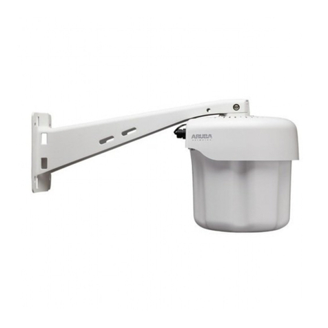
The Aruba 80 Outdoor Wireless Access Point is part of a comprehensive wireless network solution. The device
works in conjunction with the Aruba Mobility Controller and can act as a wireless access point or air monitor.
As a wireless Access Point (AP), the Aruba 80 Outdoor Wireless Access Point (also referred to asthe Aruba 80)
provides transparent, secure, high-speed data communications between wireless network devices (fixed,
portable, or mobile computers with IEEE 802.11a (country regulatory domain permitting) or IEEE 802.11b/g
wireless adapters) and the wired LAN.
As a wireless Air Monitor (AM), a feature unique to Aruba products, the Aruba 80 Outdoor Wireless Access Point
enhances wireless networks by collecting statistics, monitoring traffic, detecting intrusions, enforcing security
policies, balancing wireless traffic load, self-healing coverage gaps, and more.
NOTE—Installing the Aruba 80 requires setting the antenna power, which requires
professional training. The Aruba 80 installer must be trained to perform this
configuration.

Model 80SB
2.4GHz, N-Type, Female
Model 80MB
5 GHz, N-Type, Female
Model 80SB
2.4GHz, N-Type, Female
Model 80MB
2.4 GHz, N-Type, Female
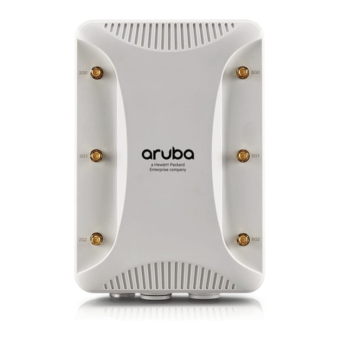
FIGURE 1-1 Aruba 80 Outdoor Wireless Access Point Front View

External Internal Antenna (2.4 GHz) Connector
For AP-80SB: 2.4 GHz, N-Type, Female connector
For AP-80MB: 5 GHz, N-Type, Female connector
External Internal Antenna (2.4 GHz) Connector
For AP-80SB: 2.4 GHz, N-Type, Female connector
For AP-80MB: 2.4 GHz, N-Type, Female connector
Internal 2.5 GHz 17.0 dBi, Directional Antenna (AP-80SB only)
FE Port
The wireless Access Point has one 10BASE-T/100BASE-TX 8-pin DIN port that connects to the power
injector module using the included Ethernet cable. The Ethernet port connection provides power to the
wireless Access Point as well as a data link to the local network.
The wireless Access Point appears as an Ethernet node and performs a bridging function by moving packets
from the wired LAN to the remote end of the wireless Access Point link.
NOTE: The power injector module does not support Power over Ethernet (PoE) based on the IEEE 802.3af
standard. The wireless Access Point unit must always be powered on by being connected to the
power injector module.
RSSI Connector
Not used.
Grounding Screw
Even though the wireless Access Point includes its own built-in lightning protection, it is important
that the unit is properly connected to ground. A grounding screw is provided for attaching a ground
wire to the unit.
NOTE: The Aruba 80 requires lightening protection. Aruba recommends the use of lightening arresters.
Failure to provide protection from lightening strikes will void the warranty for this product.
See Appendix B for port and cable specifications.

Rear View
Mounting bolts
Vertical mounting indicator
This is the vertical integrated antenna polarization indicator.
Horizontal mounting indicator.
This is the horizontal integrated antenna polarization indicator.
See Appendix B for port and cable specifications.

The Aruba AP Setup Process
Setting up an Aruba AP typically consists of four stages:
1 WLAN Planning—The administrator determines how many Aruba APs will be needed for their wireless network
strategy and where they will be deployed. This can be easily accomplished using Aruba’s automated RF Plan
site-survey software (available separately).
2 AP Provisioning—Provisioning provides each Aruba AP with initial settings that allow it to locate the host Aruba
Mobility Controller. Depending on the network topology and services, AP provisioning can be performed
manually for each AP or plug-and-play for batches of APs.
AP provisioning is discussed in “Provisioning Access Points”.
3 AP Deployment—Once provisioned, each AP can be physically installed at its intended place of operation.
AP deployment is covered in “Hardware Installation”.
4 AP Configuration—The administrator defines the operational behavior for each Aruba AP, such as RF
characteristics and security features.
For AP configuration information, refer to the ArubaOS Applications Configuration Guide.
System Configuration
The wireless Access Point receives power through a special cable (sold separately) to connect to the
non-802.3af-complaint Power over Ethernet injector module. The power injector module provides two
RJ-45 Ethernet ports, one for connecting to the wireless Access Point (Output), and the other for
connecting to a local LAN switch (Input).
At each location where a unit is installed, it must be connected to the local network using the
power injector module.
The Power over Ethernet injector module port uses an MDI (i.e., internal straight-through) pin
configuration. You can therefore use straight-through twisted-pair cable to connect this port to most
network interconnection devices such as a switch or router that provide MDI-X ports. However, when
connecting the access point to a workstation or other device that does not have MDI-X ports, you must
use crossover twisted-pair cable.

The wireless Access Point does not have a power switch. It is powered on when its Ethernet port is connected
to the power injector module, and the power injector module is connected to an AC power source. The power
injector includes one LED indicator that turns on when AC power is applied.
The power injector module automatically adjusts to any AC voltage between 100-240 volts at 50 or 60
Hz. No voltage range settings are required.
WARNING: The power injector module is designed for outdoor use only. Never mount the power injector
outside with the wireless Access Point unit.
Wall- and Pole-Mounting Bracket Kits
The wireless Access Point includes bracket kits that can be used to mount the Access Point to a wall, pole,
radio mast, or part of a tower structure.


The wireless bridge offers a variety of management options, including a web-based interface, a command line
interface (CLI), or using SNMP management software.
Most initial configuration steps can be made through the web browser interface using the Setup Wizard.
However, for units that do not have a preset country code, you must first set the country code using the CLI.
Note: Units sold in some countries are not configured with a specific country code. You must use the CLI to
set the country code and enable wireless operation.
The wireless bridge uses the IP address 192.168.1.1 by default. If this address is not compatible with your
network, you can first perform initial configuration using a PC that has IP settings compatible with this subnet
(for example, 192.168.1.2) and connecting it directly to the wireless bridge. When the basic configuration is
completed, you can set new IP settings for the wireless bridge before connecting it to your network.
Initial Setup through the CLI
The wireless bridge provides access to the CLI through a Telnet connection. You can open a Telnet session by
performing these steps:
1. From the host computer, enter the Telnet command and the IP address of the wireless bridge unit
(default 192.168.1.1).
2. At the prompt, enter “admin” for the user name.
3. The default password is null, so just press [Enter] at the password prompt.
The CLI will display the “Aruba Networks AP-80MB#” prompt to show that you are using executive access
mode (i.e., Exec).
Username: admin
Password:
Aruba Networks AP-80MB#

Initial Configuration Steps
Setting the Country Code – Regulations for wireless products differ from country to country. Setting the
country code restricts the wireless bridge to use only the radio channels and power settings permitted in the
specified country of operation. If the wireless bridge unit is shipped with a preset country code, you are not
permitted to change it, as required by country regulations. If the unit is set to the default “99,” you must set the
country code to the country of operation.
At the Exec prompt, type “country ?” to display the list of country codes. Check the code for your country, then
enter the country command again followed by your country code (e.g., IE for Ireland).
Aruba Networks AP-80MB#country ie
Aruba Networks AP-80MB#
Setting the IP Address – By default, the wireless bridge is configured with the IP address 192.168.1.1. You
may also use the CLI to assign an IP address that is compatible with your network.
Type “configure” to enter configuration mode, then type “interface ethernet” to access the Ethernet
interface-configuration mode.
Aruba Networks AP-80MB #configure
Aruba Networks AP-80MB (config)#interface ethernet
Aruba Networks AP-80MB (config-if)#
Type “ip address ip-address netmask gateway,” where “ip-address” is the wireless bridge’s IP address,
“netmask” is the network mask for the network, and “gateway” is the default gateway router. Check with your
system administrator to obtain an IP address that is compatible with your network.
Aruba Networks AP-80MB (if-ethernet)#ip address 192.168.2.2 255.255.255.0 192.168.2.254
Aruba Networks AP-80MB (if-ethernet)#
After configuring the wireless bridge’s IP parameters, you can access the management interface from
anywhere within the attached network. The command line interface can also be accessed using Telnet from
any computer attached to the network.

Using the Web-based Management Setup Wizard
There are only a few basic steps you need to complete to set up the wireless bridge for your network. The
Setup Wizard takes you through configuration procedures for the radio channel selection, IP configuration,
and basic WEP encryption for wireless security.
The wireless bridge can be managed by any computer using a web browser (Internet Explorer 5.0 or above, or
Netscape Navigator 6.2 or above). Enter the IP configured for the unit or the default IP address:
http://192.168.1.1
Logging In – Enter the default username “admin” and click LOGIN (there is no default password). For
information on configuring a user name and password.
The home page displays the Main Menu.
Launching the Setup Wizard – To perform initial configuration, click Setup Wizard on the home page, then
click on the [Next] button to start the process.

1. Service Set ID – Enter the service set identifier in the SSIDbox which all wireless clients must use to
associate with the access point. The SSID is case sensitive and can consist of up to 32 alphanumeric
characters (Default: DualBandOutdoor).
2. Radio Channel – You must enable radio communications for the 802.11a radio and set the operating
channel.

802.11a
Turbo Mode – If you select Enable, the wireless bridge will operate in turbo mode with a data rate of up
to 108 Mbps. Normal mode supports 13 channels, Turbo mode supports only 5 channels. (Default:
Disable)
802.11a Radio Channel – Set the operating radio channel number. (Default: 56ch, 5.280 GHz)
Auto Channel Select – Select Enable for automatic radio channel detection. (Default: Disable)
802.11b/g
802.11g Radio Channel: Set the operating radio channel number. (Range 1-11; Default: 1)
Available channel settings are limited by local regulations which determine which channels are available.
3. IP Configuration – Either enable or disable (Dynamic Host Configuration Protocol (DHCP) for
automatic IP configuration. If you disable DHCP, then manually enter the IP address and subnet
mask. If a management station exists on another network segment, then you must enter the IP
address for a gateway that can route traffic between these segments. Then enter the IP address for
the primary and secondary Domain Name Servers (DNS) servers to be used for host-name to IP
address resolution.
DHCP Client – With DHCP Client enabled, the IP address, subnet mask and default gateway can be
dynamically assigned to the access point by the network DHCP server. (Default: Disable)
If there is no DHCP server on your network, then the access point will automatically start up with its default IP
address, 192.168.1.1.
4. WDS Settings – To set up a wireless bridge link, you must configure the WDS forwarding table by
specifying the wireless MAC address of the bridge to which you want to forward traffic. For a Slave
bridge unit, you need to specify the MAC address of the wireless bridge unit at the opposite end of the
link. For a Master bridge unit, you need to specify the MAC addresses of all the Slave bridge units in
the network.

Set the distance value used to adjust timeout values to take into account transmit delays due to link
distances in the wireless bridge network. For a point-to-point link, specify the approximate distance
between the two bridges. For a point-to-multipoint network, specify the distance of the Slave bridge
farthest from the Master bridge.
5. Security – Set the Authentication Type to “Open System” to allow open access without
authentication, or “Shared Key” to require authentication based on a shared key. Enable Wired
Equivalent Privacy (WEP) to encrypt data transmissions.
Authentication Type – Use “Open System” to allow open access to all wireless clients without performing
authentication, or “Shared Key” to perform authentication based on a shared key that has been distributed to
all stations. (Default: Open System)
WEP – Wired Equivalent Privacy is used to encrypt transmissions passing between wireless clients and the
access point. (Default: Disabled)
Shared Key Setup – If you select “Shared Key” authentication type or enable WEP, then you also need to
configure the shared key by selecting 64-bit or 128-bit key type, and entering a hexadecimal or ASCII string of
the appropriate length. The key can be entered as alphanumeric characters or hexadecimal (0~9, A~F, e.g.,
D7 0A 9C 7F E5). (Default: 128 bit, hexadecimal key type)
64-Bit Manual Entry: The key can contain 10 hexadecimal digits, or 5 alphanumeric characters.
128-Bit Manual Entry: The key can contain 26 hexadecimal digits or 13 alphanumeric characters.
All wireless devices must be configured with the same Key ID values to communicate with the access point.
6. Click Finish.

7. Click the OK button to restart the access point.

This manual suits for next models
1
Table of contents
Other Aruba Wireless Access Point manuals

Aruba
Aruba 228 Series User manual

Aruba
Aruba AP-130-MNT-C2 User manual

Aruba
Aruba AP-207 User manual

Aruba
Aruba 518 Series User manual

Aruba
Aruba AP 70 User manual

Aruba
Aruba AP-303H Series User manual

Aruba
Aruba 324 User manual

Aruba
Aruba IAP-228 User manual

Aruba
Aruba 500 Series User manual

Aruba
Aruba AP-205H User manual

Aruba
Aruba 203H User manual

Aruba
Aruba Instant On AP12 User manual

Aruba
Aruba AP-504 RW User manual

Aruba
Aruba AP-92 User manual

Aruba
Aruba 310 Series User manual

Aruba
Aruba 200 Series User manual

Aruba
Aruba 530 Series User manual

Aruba
Aruba 303P Series User manual

Aruba
Aruba 220 Series User manual

Aruba
Aruba 300 series User manual