Copyright © 2016 Ruckus Wireless, Inc.
Published June 2016, Part Number 800-71267-001 Rev A Page 2 of 4
Figure 3. Complete the Setup Wizard to set up your Unleashed network
8Once the Setup Wizard is finished, a “Configuring system settings and rebooting”
progress screen appears. Wait until the process is complete. This process should
take approximately three minutes.
9Connect to the WLAN that you configured in the Setup Wizard, and click OK to
reconnect. You will be redirected to the Unleashed login screen.
10 Enter your Admin Name and Password to login.
11 Upon successful login you will be presented with the Unleashed Dashboard, which
displays an overview of your Ruckus Unleashed network.
Figure 4. : The Unleashed Dashboard
12 Click OK to save your changes.
Your changes are put into effect immediately. Continue with Step 4: Customize Your
Wireless LANs.
Step 4: Customize Your Wireless LANs
Once the Unleashed Master AP has been initialized, you can fine-tune the settings of your
first WLAN (that you created during the setup wizard), and create any additional WLANs
needed prior to attaching additional Unleashed member APs. Then, when you deploy
additional member APs in whatever order you prefer, they will automatically retrieve all
WLAN configuration settings (and any other settings you have configured) from the
Unleashed Master AP.
1From the Dashboard, click anywhere in the WiFi Networks section to expand the
display of your deployed WLANs.
2On the left side of the screen, select the WLAN box for the WLAN you would like to
configure, and click the Edit button to edit the configuration; or click Create to create
a new WLAN.
3If you made any changes to the original WLAN, you will be disconnected and will need
to reconnect once the changes have been deployed on the AP radios.
Congratulations! Your Unleashed network is now configured and ready for use. You may
now proceed to Step 5: Deploy Additional Unleashed Access Points.
Step 5: Deploy Additional Unleashed Access Points
Deploying additional Unleashed member APs is simply a matter of connecting them to the
same Layer 2 network (subnet) and providing power. They will discover the Unleashed
Master and join automatically. No additional steps are necessary.
PHYSICAL INSTALLATION
Step 1: Connecting and Sealing the RJ-45 Cables
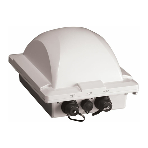
The Unleashed T710 may use zero, or one or two RJ-45 cables, one for Ethernet when
configured as a Root AP (RAP), and another when the Unleashed T710 is supplying PoE out
to a peripheral device, such as a small cell or micro cell radio. When the Unleashed T710
uses RJ-45 cables, connect and seal the cables using the M25 data cable glands as
shown in Figure 3.
WARNING: Do not use any PoE injector not tested and approved by Ruckus Wireless to
power the Unleashed T710 Access Point.
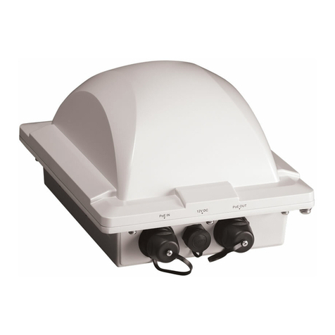
WARNING: Do not plug PoE IN power into the PoE OUT port. See Figure 2.
WARNING: If using PoE OUT, it is MANDATORY to use the custom Ruckus supplied
60W PoE injector (part #902-0180-XX00), or to use AC power.
WARNING: If using a PoE switch to supply power to the Unleashed T710, 30W MUST be
reserved for the Unleashed T710 on the switch. Failure to ensure a 30W supply may result
in unpredictable operation of the access point. Additionally, if using a PoE switch, the
Unleashed T710’s PoE OUT port cannot be used to power additional devices.
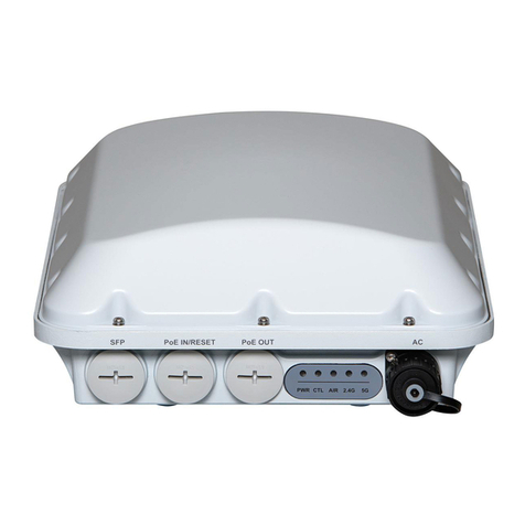
Figure 2: PoE IN and PoE OUT ports
1Feed the end of the cable through the sealing nut, rubber O-ring, clamping ring
assembly and cable gland base as shown in Figure 3.
Figure 3: RJ-45 cable and cable gland assembly
2Use a wide flat-blade screwdriver to remove the required (RESET/PoE OUT or PoE IN)
blanking cap from the Unleashed T710.
3Connect the cable to the Ethernet port in the Unleashed T710.
4Tighten the cable gland base into the Unleashed T710 chassis to 7 N.m or 62 in-lbs.
5Wrap the clamping ring assembly around the rubber O-ring. Make sure that the
clamping ring assembly fully encloses the rubber O-ring.
6Seat the clamping ring assembly and rubber O-ring in the cable gland base.
7Hand-tighten the sealing nut.
STEP 1A: CONNECTING THE SFP OPTIC MODULE TO
THE FIBER PORT
To connect to fiber backhaul, plug an SFP Optic module into the Fiber port. The SFP
module is hot-swappable and can be removed with fingers or simple tools.
NOTE: Recommended modules specified to work with this system are: Finisar GPON
FTGN2117P2TUN, Finisar EPON FTEN2217P1CUN-BC, Finisar 1000BaseLX
FTLF1318P3BTL, Xavi XO-3901 GPON ONT.
NOTE: The fiber cable must be a single diameter cable, not a zipcord.
Figure 4: SFP module cable gland assembly
STEP 2: ATTACHING THE U-JOINT BRACKET TO THE
MOUNTING BRACKET
1Position the U-joint bracket on the mounting bracket.
NOTE: Mount the U-joint bracket in any direction on the mounting bracket,
preferably to allow AP azimuth adjustments. Then the AP bracket allows
AP elevation adjustments.
Figure 5: U-joint bracket attached horizontally to the mounting bracket
2Use four 1/4-28 bolt and washer sets (A) to mount the U-joint bracket (B) to the
mounting bracket (C). Tighten the bolts to 9.5 N.m (7 ft-lbs).
3Continue with Step 3a: Attaching the Mounting Bracket to a Flat Surface or
Step 3b: Attaching the Mounting Bracket to a Metal Pole.
Cable gland base
Clamping ring assembly
Rubber O-ring
Sealing nut
