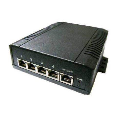
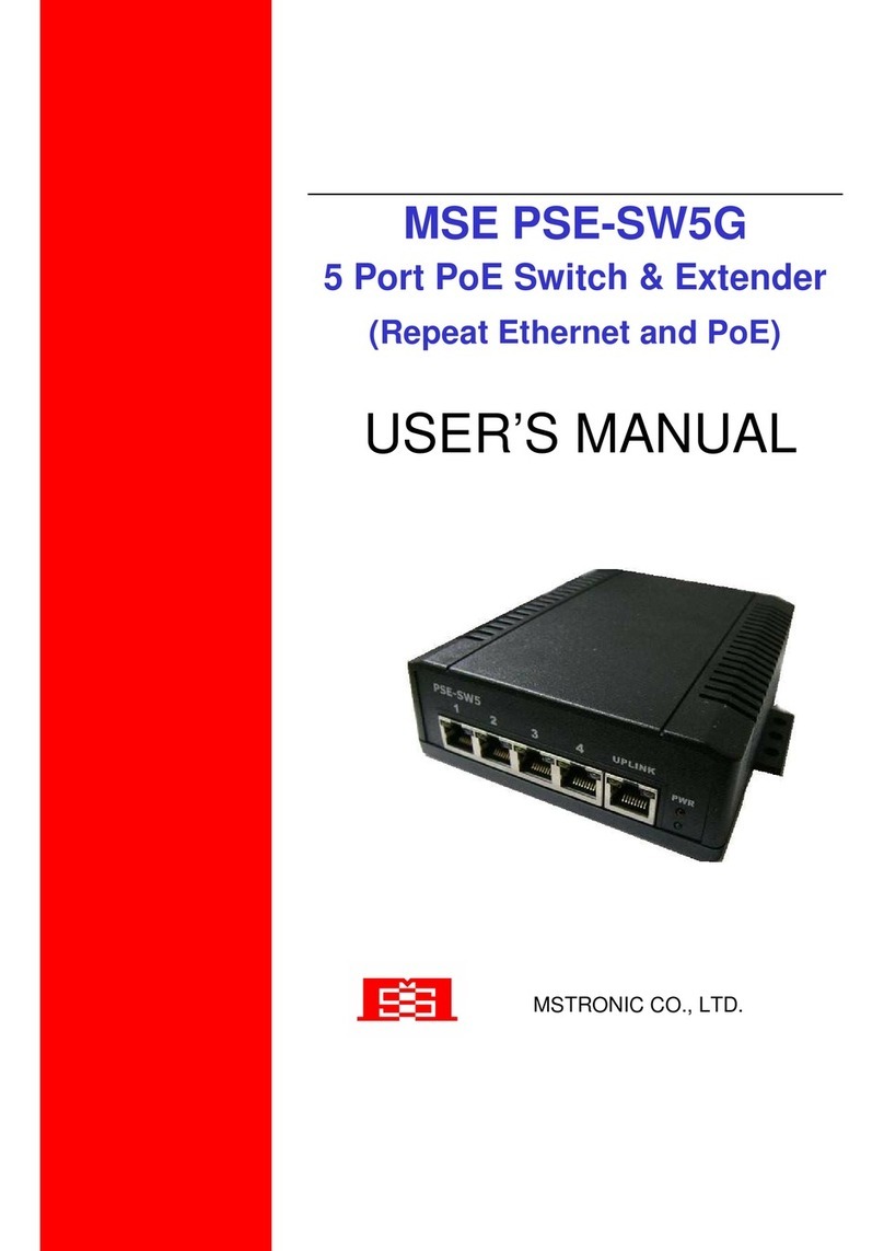
MSTRONIC DIN-SW5G44x4 User manual

USER’S MANUAL
MSTRONIC CO., LTD.
DIN-SW5G44x4
5 Port PoE Switch & Extender
(Repeat Ethernet and PoE)

User’s Manual
DIN-SW5G44x4 series
MSTRONIC CO., LTD.
2
1. General Information
The DIN-SW5G PoE (Power Over Ethernet) Switch family provi es four 10M/100M/1000M TX
ports with PoE PSE function plus one 10M/100M/1000M TX up-link port with PoE PD function. It
accepts power from PoE power souring equipment (PSE) an elivers power to PoE powere
evice (PD), which are compliant with IEEE802.3af an IEEE802.3at stan ar to receive an
eliver both Ethernet ata an DC power through the tra itional UTP or STP cable. The PoE
Switch can exten Ethernet ata an DC power up to 200 meters.
2. Hardware Description
*LED Indicator
There are 12 LEDs on the PoE switch to in icate the status of power an signal. The following
section escribes the functions of each LED in icator.
Front panel etail

User’s Manual
DIN-SW5G44x4 series
MSTRONIC CO., LTD.
3
*POWER LED
LED
STATUS
Description
Power
Green
LED ON when power input (DC IN on
top pane or UPLINK on front pane ) has
va id power supp ied.
Red The indicator is unused for the mode
Off No power supp ied.
*SWITCH LED (the upper indicator on each RJ45)
LED STATUS Description
P1~P4 and UPLINK
Link/Act
Green
A network device is detected (1000Mbps),
but no communication activity is detected.
Green
B inking
This port is transmitting to, or receiving
package from another device at 1000Mbps.
Ye ow A network device is detected (10Mbps or
100Mbps), but no communication activity
is detected.
Ye ow
B inking
This port is transmitting to, or receiving
package from another device at 10Mbps or
100Mbps.
Off No device is detected.
*PoE LED (the ower indicator on each RJ45)
P1~P4
PoE
Ye ow
A va id Powered Device (PD) is detected
and de ivering power on this port.
Off
No PD is detected on this port.
UPLINK
PoE
Ye ow
Power via another PoE
Powered on a 4 data pairs.

User’s Manual
DIN-SW5G44x4 series
MSTRONIC CO., LTD.
4
Ye ow
B anking
Powered on 2 data pairs. (1,2,3,6 or 4,5,7,8
are a acceptab e).
Off No power is detected on this port.
*Power wiring
The PoE switch fami y a ows it to be powered by another PoE source on port UPLINK as a PoE
repeater or extender. For DIN-SW5G44x4 is 44~57VDC.
For PoE operation, make sure your power supp y can offer at east 75W for 4x 802.3af PoE port, or
150W for 4x 802.3at PoE port.
If powered via the top termina , p ease make sure the input current is not over 10A. tota output 8A
maximum. If powered on port UPLINK, the input current is not over 2Amp. Tota output 2A
maximum.
Ports 1~4 wi de iver DC power over the Ethernet cab e as detai ed be ow:
Mode A:
* Data pair A p us V+ on ine 1 and 2
* Data pair B p us V- on ine 3 and 6
* Data pair C on ine 4 and 5
* Data pair D on ine 7 and 8
Mode B:
* Data pair A on ine 1 and 2
* Data pair B on ine 3 and 6
* Data pair C p us V+ on ine 4 and 5
* Data pair D p us V- on ine 7 and 8
Mode D (dua ,=A+B):
* Data pair A p us V+ on ine 1 and 2
* Data pair B p us V- on ine 3 and 6
* Data pair C p us V+ on ine 4 and 5
* Data pair D p us V- on ine 7 and 8

User’s Manual
DIN-SW5G44x4 series
MSTRONIC CO., LTD.
5
Port UPLINK may receive DC power over the Ethernet cable, as etaile below:
* Data pair A plus V+ /V- on line 1 an 2
* Data pair B plus V-/V+ on line 3 an 6
* Data pair C plus V+/V- on line 4 an 5
* Data pair D plus V-/V+ on line 7 an 8
The terminal block on the top panel shoul be wire as etaile below:
*For 48VDC typical mo el(DIN-SW5G44x4)
The input voltage must be in the range of 44 to 57VDC if running for 802.3af operation.
The input voltage must be in the range of 50 to 57VDC if running for 802.3at operation.
If the 48VDC typical mo el is not powere with the above esignate input voltage, it will only
function as an Ethernet switch without PoE output.

User’s Manual
DIN-SW5G44x4 series
MSTRONIC CO., LTD.
6
Model Input Voltage
(TOP)
Input Voltage
(Port
UPLINK)
Output voltage 802.3af at
Isolated
DIN-SW5G44A4
DIN-SW5G44B4
DIN-SW5G44D4
44-57VDC No input 44-57VDC
(non-regu ated) Yes No
No input 44-57VDC 44-57VDC
(non-regu ated) Yes No
44-57VDC 44-57VDC
Higher vo tage
output
(TOP or Port
UPLINK)
Yes No
*Ethernet Port Wiring
The PoE switch fami y supports one RJ-45 up ink (port UPLINK with PoE PD) and four RJ-45
ports (port 1~4 with PoE PSE) with automatic MDI/MDI-X crossover, auto-sense for speed and
dup ex for 10Base-T, 100Base-TX or 1000Base-T connection. Automatic MDI/MDI-X crossover
a ows you to connect to other devices (switches, hubs, or workstations etc.), without regard to
using straight-through or crossover cab ing.
Port 1 to 4 provides Power over Ethernet function that de ivers DC power through the data pairs C
& D (pin 4,5 and pin 7,8) (mode B) to the PD. Port UPLINK provides Power Device function that
receive power from 4 pairs or 2 pairs Ethernet cab e.
The fo owing tab es describe the wiring diagram of straight-through and crossover cab ing. The
crossover cab es simp y cross-connect the transmit ines at each end to the receive ines at the
opposite end.
Straight-through Cab ing
Pin 1 Pin 1
Pin 2 Pin 2
Pin 3 Pin 3

User’s Manual
DIN-SW5G44x4 series
MSTRONIC CO., LTD.
7
Pin 6 Pin 6
Pin 4 Pin 4
Pin 5 Pin 5
Pin 7 Pin 7
Pin 8 Pin 8
Cross-over Cab ing
Pin 1 Pin 3
Pin 2 Pin 6
Pin 3 Pin 1
Pin 6 Pin 2
Pin 4 Pin 7
Pin 5 Pin 8
Pin 7 Pin 4
Pin 8 Pin 5
Connect an Ethernet cab e into any switch port and connect the other side to your
attached device. The Link/Act LED (green or ye ow) wi ight up when the cab e is correct y
connected. Refer to the LED Indicator section for descriptions of each LED indicator.
If a port LED is off, go back and check for connectivity prob ems between that port and the network
device connected.
The maximum cab e ength for 10/100/1000BaseT with Cat 5 twisted pair cab es is typica y 100m
(328 ft.).
*PD Port Wiring
Port 1 to 4 provides PoE injection function with maximum 35W abi ity to power up the powered
device using the straight-through or cross-over Ethernet cab e.
The PoE switch fo ows the IEEE802.3af A ternative B mode connector assignment. The fo owing
tab e shows pin assignment of a ternative A and B for the Power Source Equipment.

User’s Manual
DIN-SW5G44x4 series
MSTRONIC CO., LTD.
8
Conductor Alternative A
(MDI-X)
Alternative A
(MDI)
Alternative B
(All)
1 Negative Vport Positive Vport
2 Negative Vport Positive Vport
3 Positive Vport Negative port
4 Positive Vport
5 Positive Vport
6 Positive Vport NegativeVport
7 Negative Vport
8 Negative Vport
Be sure the twisted pair cab e is bound with the standard RJ-45 pin, especia y the pins 4, 5, 7 and 8.
If the RJ-45 is bound with the wrong pin number, the PoE switch wi not recognize the PD and
won’t de iver DC power to the PD. The ye ow PoE LED wi ight up when the cab e is correct y
connected. Refer to the LED Indicator section for descriptions of each LED indicator. If a port
LED is off, go back and check for connectivity prob ems between that port and the network device
connected.

User’s Manual
DIN-SW5G44x4 series
MSTRONIC CO., LTD.
9
*Network Application
The PoE Switch can receive power from a PoE mi span an provi e power to the PD which
follows the IEEE 802.3af/at stan ar in the network. The PoE Switch can be installe in a more
appropriate position for better performance to exten Ethernet to 200 meters. The following figure
is an example of a network application for the PoE Switch.
3. Model Information
Model number Input Voltage Vout/pin out/Iout Output Wattage
Remark
DIN-SW5G44A4 44-5 VDC(DC)
44~5 VDC(POE)
Vi/1236/0.625A 35W/port 802.3at
DIN-SW5G44B4 44-5 VDC(DC)
44~5 VDC(POE)
Vi/45 8/0.625A 35W/port 802.3at
DIN-SW5G44D4 44-5 VDC(DC)
44~5 VDC(POE)
Vi/1236+45 8/0.625A 35W/port 802.3at

User’s Manual
DIN-SW5G44x4 series
MSTRONIC CO., LTD.
10
4. Technical Specifications
Standards IEEE802.3/IEEE802.3u standards/IEEE802.3ab (10
base-T/100base-TX/1000base-T)
Ports 5 ports with PoE (4 PSE & 1 PD), support auto-crossover &
auto-po arity
Transmission speed 1000Mbps (1000base-T).100 Mbps (100base-TX), 10 Mbps(10base-T)
Auto-negotiation
Switch techno ogy store-and-forward
Protoco s CSMA/CD
F ow contro IEEE802.3x (fu -dup ex), back pressure (ha f-dup ex)
Data transmission rate 1488000pps for1000base-T, 148800pps for 100base-T, 14880pps for
10base-T
Address tab e 2K MAC address tab e, se f- earning
Connect RJ-45
PoE port Port 1-4, PSE auto power management
Pin assignment:
*A mode:
data pair A p usV+(1,2),
data pair B p usV-(3,6),
data pair C (4,5),
data pair D (7,8)
*B mode:
data pair A (1,2),
data pair B (3,6),
data pair C p usV+(4,5),
data pair D p us V-(7,8)

User’s Manual
DIN-SW5G44x4 series
MSTRONIC CO., LTD.
11
*A+B mode:
data pair A p usV+(1,2),
data pair B p usV-(3,6),
data pair C p usV+(4,5),
data pair D p us V-(7,8)
Port UPLINK, 4 pairs PD
Maximum PoE power Port 1-4: IEEE802.3af – 16.8W
IEEE802.3at – 35W
Port UPLINK: 90W (802.3at 2 event c assification)
DIN disconnect mode DC disconnect
PoE auto detection IEEE802.3af & IEEE802.3at (2 event c assification signa ing)
PoE protection Over-temperature, over-current, over/under vo tage
LEDs *Link/Activity (Green ON/ Green B inking @1000Mbps,
Ye ow/Ye ow B inking @10M/100Mbps)
*PoE (Ye ow) port 1-4 ON - PD detect
Port UPLINK DIN-SW5G44x4
ON – 4 pair power, B inking-2 pair power
*POWER Green-norma , Red-a arm
Power input Port UPLINK (UPLINK) from network switch or midspan, or optiona
DC power supp y.
Power consumption ess than 5W when without PD oading
Input DIN-SW5G44x4
12V 0.190A
24V 0.104A
48V 0.061A
56V 0.056A
Power efficiency 85% at fu oad (@48V typica )

User’s Manual
DIN-SW5G44x4 series
MSTRONIC CO., LTD.
12
Operating temperature
-20℃~ +70℃
Operation humi ity 90% relative humi ity, non-con ensing
Storage temperature
-40℃~+85℃
Dimension 125mm(H)x46mm(W)x102mm(D) DIN RAIL Mounting
Table of contents
Other MSTRONIC Network Router manuals
Popular Network Router manuals by other brands

3Com
3Com NJ225 - IntelliJack FX-SC Switch user guide

ZyXEL Communications
ZyXEL Communications P-202H Plus v2 quick start guide

H3C
H3C MSR 5600 Command reference

Robustel
Robustel GoRugged R3000 Lite quick start guide

Draytek
Draytek Vigor3100 quick start guide

virtual access
virtual access GW9000 Series Installing