MTD Leaf Collection System User manual

5
CONTENTS OF CARTON
42”/46” Leaf Collection System
Before beginning installation, remove all parts from the carton to make sure
everything is present. Carton contents are listed below and shown in Figure 1.
The hardware pack(s) included in this kit are detailed at the end of this section.
• Cart Collection Support Assembly - 689-02019
• Mesh Cover - 764-05215
• Bagger Chute - 731-09329A
• Bag Vent - 731-12351B
• Hose End - 731-12353A
• Hose - 764-05335
• Hardware Pack - 689-00636
50”/54” Leaf Collection System
Before beginning installation, remove all parts from the carton to make sure
everything is present. Carton contents are listed below and shown in Figure 2.
The hardware pack(s) included in this kit are detailed at the end of this section.
• Cart Collection Support Assembly - 689-02019
• Mesh Cover - 764-05215
• Bagger Chute Assembly - 819-010964
• Bag Vent - 731-12351B
• Hose End - 731-12353A
• Hose - 764-05335
• Hardware Pack - 689-02199
U-Shape Tube Adjustment
Tube
Upright Tube
Corner Tube
Top/Bottom
Stop Plate
Center Stop
Plate
Bag Vent
Mount Tube
Figure 1
Upright Tube
Corner Tube
U-Shape Tube Adjustment
Tube
Top/Bottom
Stop Plate
Center Stop
Plate
Bag Vent
Mount Tube
Figure 2
Thank You
Thank you for purchasing this product. It was carefully engineered to provide excellent performance when properly operated and maintained.
Please read this entire manual prior to operating the equipment. It instructs you how to safely and easily set up, operate and maintain your equipment. Please be sure that you, and any other persons who will
operate the machine, carefully follow the recommended safety practices at all times. Failure to do so could result in personal injury or property damage.
All information in this manual is relative to the most recent product information available at the time of printing. Review this manual frequently to familiarize yourself with the equipment, its features and
operation. Please be aware that this Operator’s Manual may cover a range of product specifications for various models. Characteristics and features discussed and/or illustrated in this manual may not be
applicable to all models. We reserve the right to change product specifications, designs and equipment without notice and without incurring obligation.
If you have any problems or questions concerning this equipment, phone your local dealer or contact us directly. We want to ensure your complete satisfaction at all times.
Throughout this manual, all references to right and left side of the machine are observed from the operating position.

6
CONTENTS OF CARTON
Contents of Hardware Pack(s)
Please check your hardware pack(s) against the illustrations below. The quantities for each item are listed in parentheses.
42”/46” Hardware Pack 689-00636
738-1225 712-04064
(1)
747-06043
(2)(2)
(2)
712-04064
738-1225
747-06309
(2)
(1)
50”/54” Hardware Pack 689-02199

7
ASSEMBLY & INSTALLATION
NOTE: References to left, right, front and rear of the leaf collection system are from the operator’s
position, unless otherwise stated.
WARNING
Before beginning installation, place the mower on a firm and level surface,
set the parking brake, place the PTO in the disengaged (OFF) position, stop
the engine/motor and remove the key to prevent unintended starting.
Assemble the Leaf Collection System Frame
1. Lay one corner tube on a firm, level surface as shown in Figure 3.
2. For the left frame assembly, align one
upright tube with the corner tube using
the mounting hole and secure with one
pan head screw and one hex nut as shown
in Figure 3.
NOTE: When assembling the frame, it is best to not
fully tighten the hardware at this time. This will
facilitate the alignment process.
3. Align second upright tube to corner tube
and secure with one pan head screw and
one hex nut as shown in Figure 4.
4. Attach additional corner tube to free ends
of upright tubes, aligning with mounting
holes and secure with two pan head
screws and two hex nuts as shown in
Figure 5.
5. Tighten all of the hardware installed at
this time with torx tool and 1/2” wrench
as shown in inset of Figure 5.
6. For the right frame assembly, repeat steps
1-5 with remaining corner tubes, upright
tubes and associated hardware.
7. Attach bag vent mount tube to right
frame assembly, using two pan head
screws and two hex nuts as shown in
Figure 6.
8. Snap bag vent (731-12351B) in place
by rotating and placing the upper tab
as shown in Figure 7, then clipping the
bottom portion onto the bag vent mount
tube (see lower inset, Figure 7).
9. Align left and right frame assemblies as
shown in Figure 8.
10. Insert adjustment tube into bottom front
of left frame assembly as shown in inset
of Figure 8, turning until spring button
snaps into place in the hole farthest from
the edge.
11. Insert opposite end of adjustment
tube into bottom front of right frame
assembly, depress spring button to allow
tube to slide but do not snap into place.
12. Repeat process with bottom back of right
and left assembly with adjustment tube.
Once both sides are assembled, slide
adjustor tubes into right assembly until
spring buttons snap into the holes
farthest from the edge.
13. Install four adjustment tubes into the two
u-shape tubes, sliding until spring
buttons snap into the middle holes as
shown in Figure 9.
14. Insert u-shape tubes into left and right
frame assemblies by sliding adjustment
tubes into corner tubes as shown in
Figure 10.
Install Frame Assembly on
Cart
Install leaf collection frame assembly on cart
as follows:
1. Place assembled frame into cart with
the bag vent (731-12351B) in the right
upper corner facing the mower. See
Figure 11.
Figure 3
Figure 4
Figure 5
Figure 6
Figure 7
Figure 8
Figure 9
Figure 10
Figure 11

8
ASSEMBLY & INSTALLATION
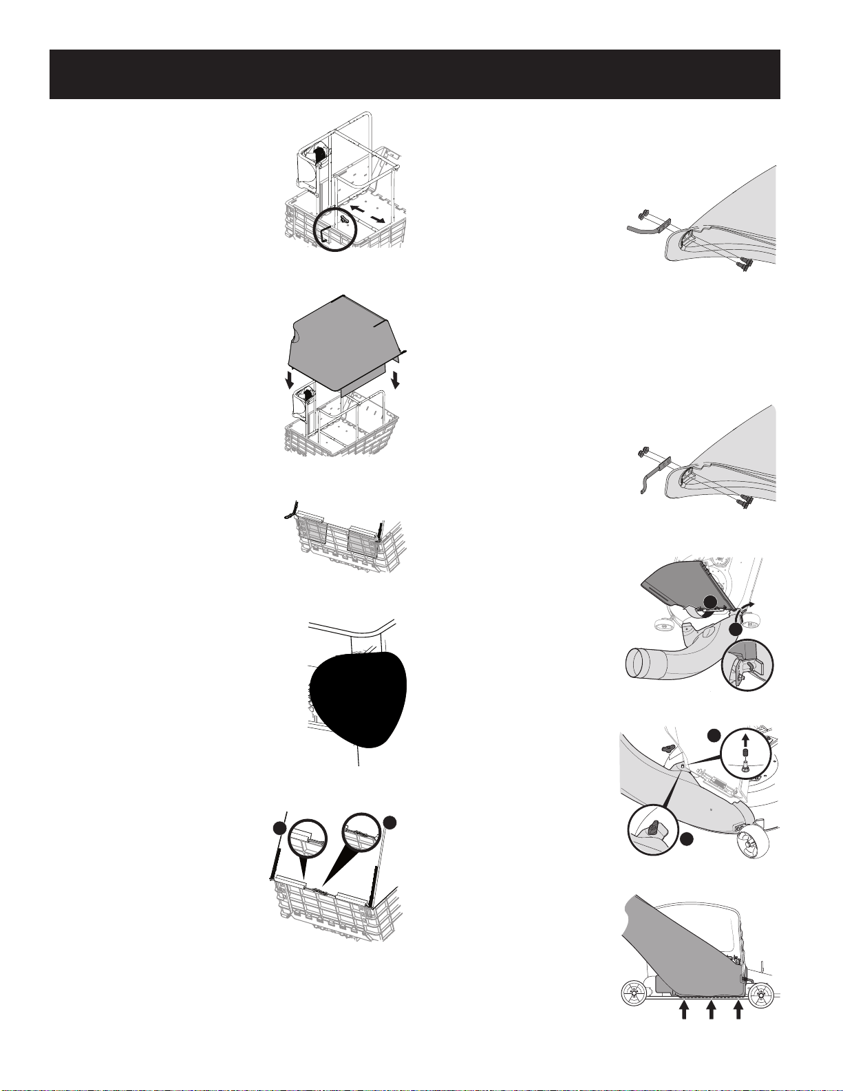
2. Adjust frame as necessary to fit width of cart
by depressing spring buttons on adjustor
tubes to adjust the width and length of
the frame, making sure the spring buttons
snap into place. See Figure 12.
3. Install vinyl cap to non-threaded end of
hook.
4. Use hook assembly to secure frame to
the cart by inserting the threaded arm of
the hook assembly through the left front
side of the frame, adjust the capped end
of the hook assembly to rest against the
outside wall of the cart and secure with
one wing knob, as shown in Figure 12.
5. Drape mesh cover (764-05215) over frame
assembly, aligning bag vent and mesh
cover opening. See Figure 13.
IMPORTANT: Be certain plastic panels on bottom
of mesh cover are located inside walls of cart, as
shown in Figure 14.
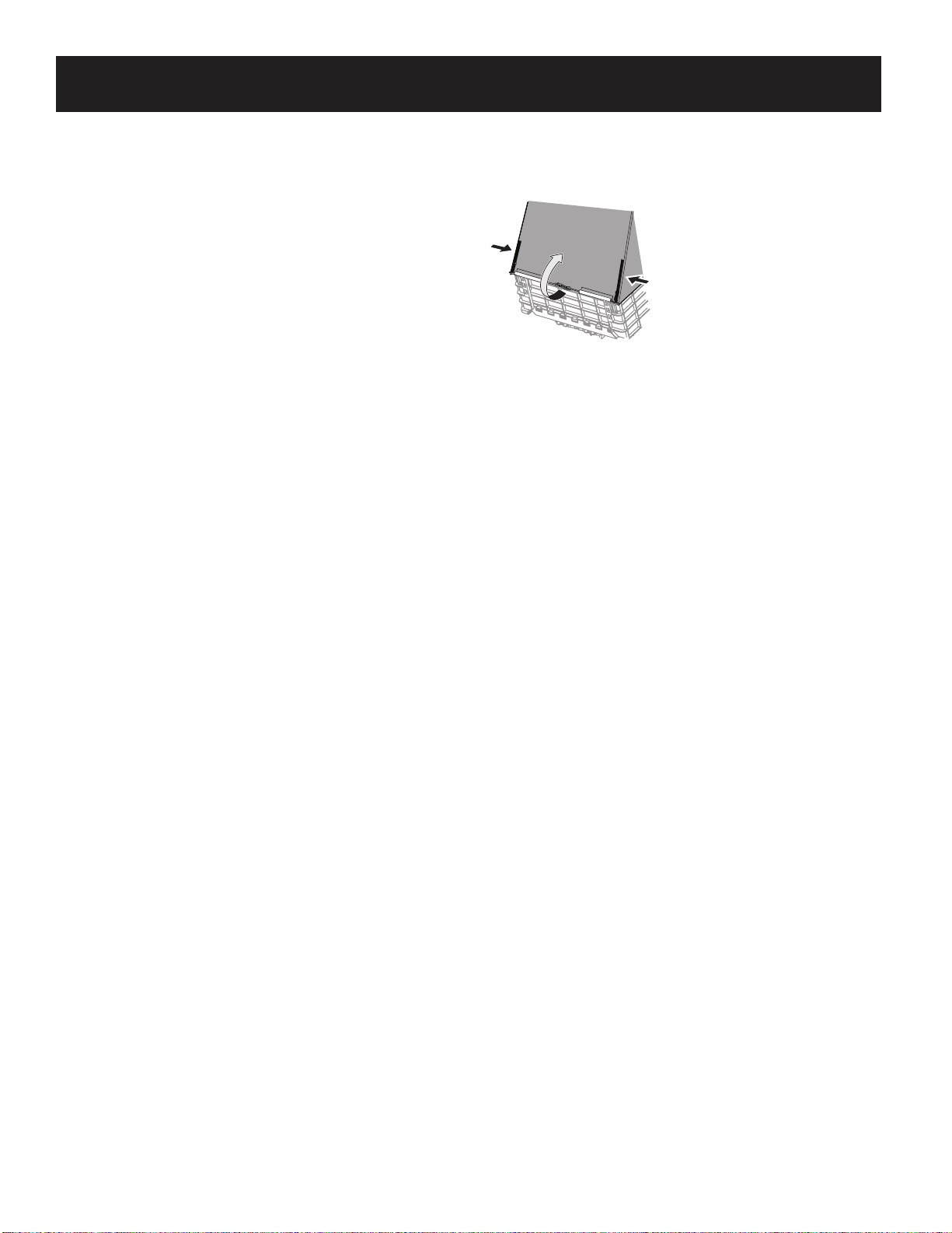
6. Stretch bottom edge of mesh cover to fit
over top of cart. Adjust mesh cover as
necessary to fit over assembled frame.
7. Stretch mesh cover opening to seal the
edges of the bag vent, as shown in Figure
15.
8. At rear of cart, pull bottom edges of mesh
cover towards the ground until cover
reaches below top lip of cart.
9. Stretch bungy cords located at back
right and left bottom of mesh cover
horizontally towards center until attached
carabiners meet. Slide bungy cords into
channels attached to bottom of mesh cover (1)
and click carabiners together (2), as shown in
Figure 16.
IMPORTANT: Be certain that bottom of mesh cover is secured
tightly to cart and that zippers are firmly closed in order to prevent
collected material escaping from the leaf collection system.
Installing the Boot Rod & Hardware
42”/46” Models:
1. From the inside of the boot, put
two hex head shoulder screws
(738-1225) through the holes at
the bottom front of the boot. See
Figure 17.
2. Put the mounting rod (747-
06043) in place over the hex head
shoulder screws. Make sure the
tip of the rod is facing out from
the boot. See Figure 17.
3. Begin threading the hex nuts
(712-04064) onto the hex head shoulder screws. See Figure 17.
4. Using a 7/16” wrench or socket on the screw and a 7/16” box wrench on the
hex nuts, tighten down so flange is flush to secure the assembly.
50”/54” Models:
1. From the inside of the boot, put
two hex head shoulder screws
(738-1225) through the holes at
the bottom front of the boot. See
Figure 18.
2. Put the mounting rod (747-
06309) in place over the hex head
shoulder screws. Make sure the
tip of the rod is facing out from
the boot. See Figure 18.
3. Begin threading the hex nuts
(712-04064) onto the hex head
shoulder screws. See Figure 18.
4. Using a 7/16” wrench or socket on
the screw and a 7/16” box wrench
on the hex nuts, tighten down
so flange is flush to secure the
assembly.
Installing the Bagger
Chute - 42”/46” Models
1. With the mower’s discharge chute
raised up and held open (1), install
the bagger chute by placing the
bagger chute mounting rod into
the bagger chute mounting tab
(2), as shown in Figure 19.
2. Secure the bagger chute to the
deck using a wing knob from
cart collection support assembly
689-02019. See Figure 20.
NOTE: If present, remove the protective
cap off of the mounting stud on the
mowing deck as shown in the upper inset
of Figure 20.
IMPORTANT: Be certain that the bottom
of the discharge chute is located inside of
the lip of the deck opening, as shown in
Figure 21.
Figure 12
Figure 13
Figure 14
Figure 15
12
Figure 16
Figure 17
Figure 18
1
2
Figure 19
1
2
Figure 20
Figure 21

9
ASSEMBLY & INSTALLATION
Installing the Bagger Chute - 50”/54” Models
When installing the bagger chute, two different installation instructions exist. For
the 50” and 54” fabricated deck units, the bagger chute mounts directly onto the
cutting deck. For the 50” and 54” stamped decks, an adapter must first be installed.
Be sure to follow the instructions that pertain to the unit you are installing this
bagger on.
On 50”/54” Fabricated Deck
Units:
1. Raise the deck to its highest
position.
2. Raise the discharge chute (1 in
Figure22) on the deck and hold
it while you position the bagger
chute over the discharge chute
opening.
3. Insert the bagger chute mounting
rod (2) into the hole provided in
the deck wheel mount as shown
in the inset of Figure 22.
4. Pivot the bagger chute rearward
until the hole in the bagger chute
aligns with the pin on the deck.
Move the bagger chute down
onto that pin as shown in 3 of
Figure 22.
5. Secure the bagger chute to the
cutting deck using a wing knob
from cart collection support
assembly 689-02019. Refer to
Figure 23.
On 50”/54” Stamped Decks:
1. Raise the deck to its highest
position.
2. Remove the deck pin rubber
protective cap (1) in Figure 24.
3. Raise the discharge chute (2 in
Figure 24) on the deck and hold
it while you install the bagger
chute adapter (3) onto the deck as
shown in Figure 24.
4. Insert the bagger chute mounting
rod (1) into the hole provided in
the deck wheel mount as shown
in the inset of Figure 25.
5. Pivot the bagger chute rearward
until the hole in the bagger chute
elbow aligns with the pin on the
bagger chute adapter. Move the
bagger chute down onto that pin
as shown in 2 of Figure 25.
6. Secure the bagger chute elbow to
the cutting deck using a wing
knob from cart collection support
assembly 689-02019. Refer to
Figure 26.
Installing the Hose
1. Thread end of hose (764-05335) without
hose end (731-12353A) securely into the
bag vent. There are two tabs on the lower
inside part of the bag vent to allow for
secure threading. See Figure 27.
NOTE: The hose and bag vent are left-hand
threaded. Thread counterclockwise until secure.
2. Lift by the hose end handles. Slide the hose
over the bagger chute mounted on the
cutting deck, as shown in Figure 28.
3. Make sure the connection is
secure and there are no gaps
between the hose and the bagger
chute.
NOTE: If open, zip the mesh cover of
the leaf collection system closed prior to
operation.
Installing the
Jackknife Plate Assembly
WARNING
Before beginning installation, place the mower on a firm and level surface,
set the parking brake, place the PTO in the disengaged (OFF) position, stop
the engine/motor and remove the key to prevent unintended starting.
1. Stack top/bottom stop plates and center stop
plate as shown in Figure 29. Secure with two hex
head screws and two hex nuts.
2. Using a 9/16” wrench or socket on the screws
and a 9/16” box wrench on the nuts, tighten to
secure.
3. If cart is attached to mower, remove bowtie clip
from mounting pin and remove pin from mower
hitch.
4. Slide jackknife assembly on hitch, aligning holes.
NOTE: Top plate should be above hitch and bottom plate
should be below hitch.
5. Lay tongue of cart on top of
jackknife plate assembly, aligning
hole in tongue with the holes in
the jackknife plate assembly.
6. Insert mounting pin and secure
with bowtie clip as shown in
Figure 30.
1
2
3
Figure 22
Figure 23
1
3
2
Figure 24
1
2
Figure 25
Figure 26
Figure 27
Figure 28
Figure 29
Figure 30

10
OPERATION
Leaf Collection System Usage
NOTE: When leaf collection system is full, place the mower, cart and leaf collection system on a firm,
level surface, disengage the PTO, turn the mower engine (motor) off and set the parking brake.
1. Carefully release the dump mechanism on the cart, if one is present.
IMPORTANT: If using bed tilt feature to dump cart, remove hose from chute elbow prior to raising
cart bed to prevent damage to hose.
2. Open mesh cover by unzipping the two zippers upwards, and lifting the rear
flap of the mesh cover as shown in Figure 31.
3. Empty the leaves/grass clippings at a proper disposal site, using a rake to
pull the contents through the rear of the cart.
4. Close the rear flap by zipping the two zippers downwards, ensuring the
plastic flaps are tucked inside the cart, restart your towing device, release
parking brake and resume leaf/grass clipping collection.
Figure 31
Table of contents
Other MTD Lawn Mower Accessories manuals