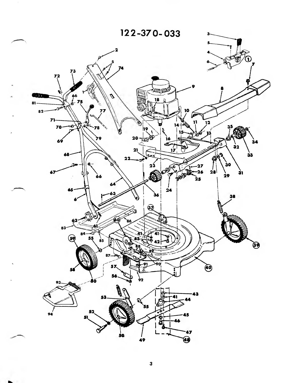
MTD 122-370-033 User manual

SAFE
OPERATION
PRACTICES
-
WALK
BEHIND
MOWERS
TRAINING
1.
Read
the
Operating
and
Service
Instruction
Manual
carefully.
Be
thoroughly
familiar
with
the
controls
and
proper
use
of
the
equipment.
2.
Never
allow
children
to
operate
a
power
mower.
3.
Keep
the
area
of
operation
clear
of
all
persons,
particularly
small
children,
and
pets.
PREPARATION
1.
Thoroughly
inspect
the
area
where
the
equipment
is
to
be
used
and
remove
all
stones,
sticks,
wire,
bones
and
other
foreign
objects.
Do
not
operate
equipment
when
barefoot
or
wearing
open
sandals.
Always
wear
substantial
footwear.
3.
Check
fuel
before
starting
engine.
Do
not
fill
gasoline
tank
indoors,
when
engine
is
running,
or
while
engine
is
still
hot.
Wipe
qff
any
spilled
gasoline
before
starting
engine.
4.
Disengage
self-propelled
mechanism
or
drive
clutch
on
units
so
equipped
before
starting
engine
(motor).
5.
Never
attempt
to
make
a
wheel
height
adjustment
while
engine
(motor)
is
running.
6.
Mow
only
in
daylight
or
in
good
artificial
light.
,
7.
Never
operate
equipment
in
wet
grass.
Always
be
sure
of
your
footing;
keep
a
firm
hold
on
the
handle
and
walk;
never
run.
i
OPERATION
1.
Do
not
change
engine
governor
settings
or
overspeed
engine.
2.
Do
not
put
hands
or
feet
near
or
under
rotating
parts.
Keep
clear
of
discharge
opening
at
all
times.
3.
Stop
blade(s)
when
crossing
gravel
drive,
walks
or
roads.
4.
After
striking
a
foreign
object,
stop
the
engine
(motor),
remove
wire
from
spark
plug,
thoroughly
inspect
the
mower
for
any
damage,
and
repair
the
damage
before
restarting
and
operating
the
mower.
5.
If
the
equipment
should
start
to
vibrate
abnormally,
stop
the
engine
(motor)
and
check
immediately
for
the
cause.
Vibration
is
generally
a
warning
of
trouble.
6.
Stop
engine
(motor)
whenever
you
leave
the
equipment,
before
cleaning
mower
housing,
and
when
making
any
repairs
or
inspections.
7.
When
cleaning,
repairing
or
inspecting,
make
certain
blade
and
all
moving
parts
have
stopped.
Disconnect
spark
plug
wire
and
keep
wire
away
from
plug
to
prevent
accidental
starting.
8.
Do
not
run
engine
(motor)
indoors.
9.
Shut
engine
(motor)
off
and
wait
until
blade
comes
to
a
complete
stop
before
removing
grass
catcher
and/or
unclogging
chute.
10.
M
ow
across
the
face
of
slopes,
never
up-and-down.
Exercise
extreme
caution
when
changing
direction
on
slopes.
Do
not
mow
excessively
steep
slopes.
11.
Always
disconnect
electric
mowers
(line
operated)
before
cleaning,
repairing,
or
adjusting.
12.
N
ever
operate
mower
without
proper
guards,
plates
or
other
safety
protective
devices
in
place.
13.
K
eep
washout
ports
and
other
mower
housing
service
openings
closed
when
mowing.
MAINTENANCE
AND
STORAGE
1.
Check
blade
and
engine
mounting
bolts
at
frequent
intervals
for
proper
tightness.
2.
Keep
all
nuts,
bolts,
and
screws
tight
to
be
sure
equip¬
ment
is
in
safe
working
condition.
3.
Never
store
equipment
with
gasoline
in
the
tank
inside
of
a
building
where
fumes
may
reach
an
open
flame
or
spark.
Allow
engine
to
cool
before
storing
in
any
enclosure.
4.
To
reduce
fire
hazard
keep
engine
free
of
grass,
leaves
or
excessive
grease.
5.
Check
grass
catcher
bags
frequently
for
wear
or
deterio¬
ration,
Replace
with
new
bags
for
safety
protection.
MTD
PRODUCTS
INC
.
5389
WEST
130th
STREET
.
P.
0.
BOX
2741
CLEVELAND
OHIO
44111
FORM
NO.
770-2522

ASSEMBLY
INSTRUCTIONS
NOTE:
Follow
Instructions
starting
with
number
1
and
continue
through
number
14.
13.
Assemble
bottom
of
handle
panel
to
handle.
2


I
s
PARTS
LIST
FOR
ROTARY
MOWER
MODEL
NO.
122-370-033
REF.
NO.
PART
NO.
DESCRIPTION
REF.
NO.
PART
NO.
DESCRIPTION
1
11597
Throttle
Control
Complete
48
10769
Blade
Adapter
Kit
2
710-473
Truss
Hd.
Mach.
Screw
10-24
x
W
Lg.
49
742-125
Blade
22"
3
305-7470
Knob—Throttle
Control
50
748-125
Sintered
Bearing—Front
4
11600
Throttle
Control
Bracket
51
711-430
Axle
Bolt—Front
Only
5
710-407
Slotted
Hex
Hd.
Self
Tap
Scr.
8-32
x
.50"
Lg.
52
736-160
Flat
Washer*
7
710-148
Hex
Hd.
Slotted
Thd.
Cut
Sew.
8-32
x
%"
Lg.*
53
10379
Link
Assembly
8
10913
Drive
Cover
55
736-300
Flat
Washer
%
Sew.*
9
____
Engine
56
710-107
Hex
Centerlock
Nut
14-20
Thd.*
10
712-324
Elastic
Stop
Nut
Thd.*
57
310-8405
Reinforcement
Plate
11
736-300
Flat
Washer
58
738-213
Axle
Bolt—Rear
Only
12
712-116
Elastic
Locknut
%-24
Thd.*
59
501-9392
Rear
Wheel
Complete
13
10395
Clutch
Rod
60'
310-8388
Handle
Mount
Bracket—R.H.
14
732-184
Extension
Spring
61
714-507
Cotter
Pin*
15
10394
Link
62
10430
Handle
Stop
Bracket
16
714-365
Hi
Pro
Key
63
715-110
Roll
Pin
3/16-Dia.
x
114"
Lg.*
17
10381
Engine
Bracket
Assembly
64
310-8398
Lower
Handle
18
710-158
Hex
Hd.
Cap
Sew,
5/16-24
x
1V4"
Lg.*
65
746-128
Cable
Clip
19
10377
Sprocket
Assembly
66
712-107
Hex
Center
Lock
Nut
14-20
Thd.*
20
748-183
Bearing
Support
67
710-106
Hex
Hd.
Cap
Sew.
14-20
x
114"
Lg.*
21
736-222
External
Lock
Washer
W*
Sew.*
68
310-9364
Upper
Handle
22
710-441
Hex
Hd.
Cap
Sew.
14-28
x
’/a"
Lg.*
69
710-256
Carriage
Bolt
14-20
x
114"
lg.*
23
10370
Pivot
Plate
70
712-324
Elastic
Stop
Nut
14-20
Thd.*
24
711-110
Shoulder
Bolt—Special
71
10474
Lockout
Bracket
25
713-135
Chain
W/Master
Link
#48
x
26"
Lg.
72
712-526
Speed
Nut
26
10378
Sprocket
Assembly
73
305-7071
Grip—Black
27
715-247
Roll
Pin
3/16
Dia.
x
1"
Lg.*
74
11605
Handle
Panel
28
748-227
Hex
Bearing
75
310-8169
Lock
Out
Lever
Assembly
29
736-860
Flat
Washer*
76
305
8132
Ball—Knob
_
„
30
716-106
"E"-Ring
%
Shaft
77
711
£17
Lock
Out
Rod
i
»7
,
?£9
31
10372
Drive
Support
78
712-^87
Hex
Nut
14-20
Thd.*
32
310-2265
Sleeve
79
736-222
External
Lock
Washer
14
Sew.*
33
10914
Drive
Pinion
80
305-7006
Fortiflex
Bearing—Rear
34
716-106
"E"-Ring
%
Shaft
81
310-7861
Throttle
Clamp
35
748-227
Hex
Bearing
82
710-606
Hex
Hd.
Cap
Screw
14-20
x
1
Vi"
Lg.*
36
711-435
Shaft
83
11163
Protective
Shield
37
310-8389
Handle
Mount
Bracket—L.H.
84
726-106
Push-on
Flange
Palnut
38
732-181
Extension
Spring
85
711-554
Hinge
Pin
39
503-9392
Front
Wheel
Complete
86
11145
Hinge
Rod
40
11659
Deck
Assembly
87
710-513
Hex
Hd.
Cap
Scr.
14-28
x
%"
Lg.
(NYLock)
41
736-119
Spring
Lock
Washer
5/16
Sew.*
88
11130
Adapter
Plate
42
710-442
Hex
Hd.
Cap
Sew.
5/16-18
x
114"
Lg.*
89
711-555
Pivot
Pin
43
712-123
Hex
Nut
5/16-24
Thd.*
90
710-289
Hex
Hd.
Cap
Scr.
14-20
x
.50"
Lg.*
44
748-189
Blade
Adapter
91
712-107
Hex
Center
Locknut
14-20
Thd.
45
736-217
Spring
Lock
Washer
%
Screw
Heavy
Duty*
92
11152
Internal
Bar
46
710-459
Hex
Hd.
Cap
Sew.
%-24
x
\W
Lg.
Heat
Treated
93
732-253
Torsion
Spring
47
710-117
Hex
Hd.
Cap
Sew.
5/16-24
x
1"
Lg.
Heat
Treated
94
11141
Chute
Deflector
350—Highland
Green
When
ordering
parts,
if
color
or
finish
is
important,
use
the
appropriate
color
code
shown
above
(e.g.
Highland
Green—11659
(350)).
4

The
engine
is
not
under
warranty
by
the
mower
manufacturer.
If
repairs
or
service
is
needed
on
the
engine,
please
contact
your
nearest
authorized
engine
service
outlet.
Check
the
“Yellow
Pages”
of
your
telephone
book
under
“Engines
-
Gasoline.”
This
mower
should
be
broken
in
following
the
procedure
described
in
the
break-in
instructions.
The
added
effort
here
will
double
the
service
life
of
the
unit.
Particular
attention
should
be
paid
to
the
notes
on
alignment.
When
operating
this
mower,
unnecessary
or
excessive
en¬
gaging
of
the
drive
pinions
with
the
wheels
should
be
avoided.
This
is
achieved
by
minimizing
the
raising
and
lowering
of
the
handle
during
the
mowing
operation.
Failure
to
observe
is
in
the
forward
position,
the
drive
pinions
engage
with
the
gear
tread
tires
and
forward
drive
results.
6.
Temporary
free
wheeling
is
achieved
by
depressing
the
handle
and
raising
front
wheels
slightly
off
the
ground.
Self-propelled
drive
is
resumed
when
handle
is
released...
Engine
is
stopped
by
placing
control
lever
on
handle
into
“Stop”
position.
this
operating
rule
can
reduce
the
service
life
of
the
front
tires
and
drive
pinions
substantially.
When
engaging
the
self-
propelled
mechanism,
a
slight
forward
push
on
the
mower
as
the
drive
pinions
and
the
gear
tread
tires
mesh
will
add
to
smoother
and
quieter
operation.
In
addition
to
a
smoother
operation,
it
will
add
substantially
to
the
service
life
of
both
the
tires
and
the
drive
pinions.
HANDLE
ASSEMBLY
PRECAUTIONS
Although
the
handle
is
of
a
simple
design,
difficulty
has
been
encountered
in
its
assembly.
Certain
precautions
con¬
cerning
its
assembly
must
be
heeded.
The
handle
must
be
assembled
as
shown
in
the
diagram.
Trouble
arises
when
certain
parts
are
put
together
improperly.
A.
Lockout
control
lever
must
be
mounted
as
shown
in
the
illustration.
LUBRICATION
IMPORTANT:
Always
stop
engine
and
disconnect
spark
plug
wire
before
cleaning,
lubricating
or
doing
any
kind
of
work
on
lawn
mower.
WHEELS
—
The
bearing
on
the
rear
wheels
of
your
lawn
mower
are
made
of
Lifetime
Fortiflex.
No
lubrication
is
re¬
quired.
Lubricate
front
wheel
bearing
as
needed.
THROTTLE
—
Periodically
lubricate
throttle
control
lever
and
throttle
wire
assembly
with
a
few
drops
of
light
oil
(S.A.E.
No.
10
or
20)
for
ease
of
operations.
BRONZE
BEARINGS
—
Periodically
lubricate
all
bronze
bearings
with
a
few
drops
of
light
oil
(S.A.E.
No.
10
or
20)
to
minimize
friction.
ENGINE
—
Follow
Engine
Manual
for
lubrication
instructions.
B.
The
lockout
control
lever
bracket
must
be
mounted
CHUTE
DEFLECTOR
—
The
torsion
spring
and
pivot
with
the
projection
up
ward
as
shown
in
the
illustration.
point
should
be
lubricated
periodically
with
oil
to
prevent
C.
If
lower
handle
is
too
narrow
to
lock
into
handle
any
rast
or
bindmg
up
'
I)eflector
must
work
freel
y-
bracket,
spread
as
needed.
BREAK-IN
INSTRUCTIONS
PROTECTIVE
SHIELD
-
The
pivot
points
on
the
pr0
_
tective
shield
should
be
lubricated
periodically
with
oil
to
prevent
any
rust
or
binding
up.
1.
Before
starting
the
engine,
lubricate
all
the
bronze
bear¬
ings
on
the
drive
shaft.
The
same
oil
which
is
used
for
the
engine
may
be
used
for
this.
Check
the
lockout
control
for
proper
operation.
See
HANDLE
ASSEMBLY
PRECAUTIONS.
Check
drive
assembly
alignment.
When
the
lockout
con¬
trol
lever
is
moved
to
the
Self-Propelled
position
(as
shown
in
diagram),
the
black
nylon
drive
pinions
should
mesh
simultaneously
with
the
gear
tread
tires.
The
lock¬
out
control
lever
should
move
from
Self-Propelled
posi¬
tion
easily.
ADJUSTMENTS
CAUTION:
Do
not
at
any
time
make
any
adjustment
to
lawn
mower
without
first
stopping
engine
and
disconnecting
spark
plug
wire.
CHAIN
ADJUSTMENT
1.
Loosen
(do
not
remove)
two
hex
head
cap
screws.
(See
illustration
below.)
2.
Pull
pivot
plate
forward.
3.
Tighten
cap
screws
and
check
chain
tension.
Repeat
adjustment
if
necessary.
OPERATION
1.
Service
engine
with
gas
and
oil.
See
Engine
Manual
packed
with
lawn
mower
for
complete
instructions
for
care
and
maintenance
of
engine.
READ
DIRECTIONS
CARE¬
FULLY.
2.
Lubricate
bronze
bearings
on
drive
shaft.
3.
Check
drive
assembly
for
correct
alignment
(see
break-in
instructions.)
4.
When
ready
to
start
engine,
place
lockout
control
lever
into
free
wheeling
position.
This
is
done
by
snapping
the
lockout
control
lever
back.
Start
engine
in
accordance
with
instructions
in
Engine
Manual.
After
engine
starts,
move
throttle
control
lever
on
handle
to
the
desired
engine
speed.
5.
Lockout
control
lever
may
now
be
moved
forward
for
self-propelled
operation.
When
the
lockout
control
lever

I
CUTTING
HEIGHT
—
Adjustment
may
be
made
by
removing
and
moving
wheel
studs
to
desired
position.
Cutting
heights
will
be
raised
as
wheel
studs
are
moved
to
a
lower
hole
and
lowered
as
wheel
studs
are
moved
to
a
higher
hole
in
the
deck.
All
wheel
studs
must
be
mounted
in
a
relative
position
to
the
deck.
THROTTLE
—
If
adjustment
becomes
necessary,
the
throttle
control
wire
assembly
can
be
reset
as
follows.
1.
Loosen,
but
do
not
remove,
screw
securing
throttli
control
wire
assembly
at
engine.
2.
Move
throttle
control
lever
on
handle
to
“Fast”
position.
3.
Move
lever,
to
which
control
wire
is
fastened
at
engine,
to
full
open
position
and
retighten
screw
to
secure
throttle
control
wire
assembly.
LOCKOUT
ROD
ADJUSTMENT
1.
Engage
lockout
control
lever.
(See
illus.
below.)
All
ten¬
sion
should
be
released
from
spring.
2.
If
tension
still
remains
on
spring,
disconnect
spring
from
pivot
link,
slide
spring
up
the
lockout
rod
and
back
elastic
stopnut
off
one
turn.
3.
Reassemble
tension
spring
and
again
check
to
be
sure
spring
is
free
from
tension.
Repeat
step
3
until
the
correct
condition
is
obtained.
MAINTENANCE
CUTTING
BLADE
-
The
blade
may
easily
be
removed
for
grinding
or
replacement
as
follows:
1.
Remove
bolt
and
lockwasher
holding
blade
and
blade
adapter
to
engine
crankshaft.
2.
Remove
blade
and
blade
adapter
from
engine
crankshaft,
3.
Remove
two
bolts,
lockwashers
and
nuts
bolding
blade
When
sharpening
blade,
follow
the
original
angle
of
grind
as
a
guide.
It
is
extremely
important
that
each
cutting
edge
receives
an
equal
amount
of
grinding
to
prevent
an
unbal¬
anced
blade.
An
unbalanced
blade
will
cause
excessive
vibration
when
rotating
at
high
speeds
and
may
cause
damage
to
the
mower.
Upon
reassembly,
make
certain
all
parts
are
assembled
properly
and
tightened
securely.
DECK
—
The
underside
of
mower
deck
should
be
cleaned
after
each
period
of
use
as
grass
clippings,
leaves,
dirt
and
other
matter
will
accumulate.
This
accumulation
of
grass
clippings,
etc.,
is
undesirable
as
it
will
invite
corrosion
and
cause
an
uneven
discharge
of
grass
clippings
at
the
next
cutting.
The
deck
may
be
cleaned
by
tilting
the
mower
forward
or
on
its
left
side
and
scraping
clean
with
a
suitable
tool
or
by
washing
with
a
stream
of
water
from
a
garden
hose.
CAUTION:
Do
not
direct
the
stream
of
water
at
a
hot
engine
as
damage
to
the
engine
may
result.
STORAGE
—
The
following
steps
should
be
taken
to
prepare
lawn
mower
for
storage.
1.
Clean
and
lubricate
mower
thoroughly
as
described
in
the
preceding
instructions.
2.
Refer
to
engine
manual
for
correct
engine
storage
instructions.
3.
Coat
mower’s
cutting
blade
with
chassis
grease
to
prevent
rusting.
4.
Place
blocks
under
deck
to
raise
tires
clear
of
floor.
5.
Store
mower
in
a
dry,
clean
area.
USING
YOUR
ROTARY
MOWER
For
best
results
do
not
cut
wet
grass
because
it
tends
to
stick
to
the
underside
of
the
mower
thus
preventing
proper
discharge
of
grass
clippings.
If
wet
grass
must
be
cut,
reduce
engine
speed
and
walking
speed
to
help
distribute
the
clippings
more
effectively.
New
grass
should
be
treated
as
wet
grass,
otherwise
a
normal
walking
speed
is
about
the
right
pace
for
efficient
mowing.
The
best
mowing
pattern
is
one
that
allows
the
clippings
to
discharge
towards
the
uncut
part
of
the
lawn.
This
permits
recutting
of
the
clippings
to
further
pulverize
them.
When
cutting
high
weeds,
discharge
towards
cut
portion
then
recut
at
right
angles
to
first
direction.
Lawn
should
be
cut
in
the
fall
as
long
as
there
is
growth.
6

GRASS
CATCHER
Model
No.
192-003
is
available
as
optional
equip¬
ment
for
the
mower
shown
in
this
manual.
WARNING.
1.
The
mower
should
not
be
operated
without
the
entire
grass
catcher
or
chute
deflector
in
place.
2.
The
mower
should
not
be
operated
without
the
protective
shield
on
the
rear
of
the
deck
in
place.
NOTE:
Under
normal
usage
bag
material
is
subject
to
wear,
and
should
be
checked
periodically.
Be
sure
any
replacement
bag
complies
with
the
mower
manufacturer's
recommendations.
For
replacement
bags,
use
only
factory
authorized
replacement
bag
No.
764-119.
♦
IMPORTANT
After
striking
a
foreign
object,
stop
the
engine
(motor),
remove
wire
from
spark
plug.
Throughly
inspect
the
mower
for
any
damage,
and
repair
the
damage
before
restarting
and
operating
the
mower.
WARRANTY
For
one
year
from
date
of
purchase,
MTD
Products
Inc
will
replace
for
the
original
purchaser,
free
of
charge,
F.O.B.
factory
or
authorized
service
firm,
any
part
or
parts
found
to
be
defective
in
material
or
workmanship.
All
transportation
charges
on
parts
submitted
for
replacement
under
this
warranty
must
be
paid
by
the
purchaser.
This
warranty
does
not
include
replacement
of
parts
which
become
inoperative
through
misuse,
excessive
use,
accident,
neglect,
improper
maintenance
or
alterations
by
unauthorized
persons.
This
warranty
does
not
include
the
engine,
motor,
battery,
battery
charger
or
any
component
parts
thereof.
For
service
on
these
units
refer
to
the
applicable
manufacturer’s
warranty.
The
above
warranty
will
apply
only
to
the
original
owner
and
will
be
effective
only
if
the
warranty
card
has
been
properly
processed.
It
will
not
apply
where
the
unit
has
been
used
commercially.
Warranty
service
is
available
through
your
local
authorized
service
dealer
or
distributor.
UNDER
NO
CIRCUM¬
STANCES
WILL
THE
RETURN
OF
A
COMPLETE
UNIT
BE
ACCEPTED
BY
THE
FACTORY
UNLESS
PRIOR
WRITTEN
PERMISSION
HAS
BEEN
EXTENDED.
7

PARTS
INFORMATION
MOWER,
TILLER,
SNOW
THROWER
AND
TRACTOR
PARTS
Mower,
tiller,
snow
thrower
and
tractor
parts
are
available
through
the
authorized
service
firms
listed
below.
All
orders
should
specify
the
model
number
of
your
unit,
parts
numbers,
description
of
parts
and
the
quantity
of
each
part
required.
ENGINE
PARTS
AND
SERVICE
Engine
parts
and
service
should
be
handled
by
your
nearest
authorized
engine
service
firm.
Check
the
yellow
pages
of
your
telephone
directory
under
the
listing
Engines
—
Gasoline,
Briggs
and
Stratton
or
Tecumseh
Lauson
—
Power
Products.
A
1
Engine
&
Mower
Co.
327
East
9th
Street
Salt
Lake
City,
Utah
84102
American
Electric
Ignition
Co.
124
N.
W.
8th
Street
Oklahoma
City,
Oklahoma
73102
Auto
Electric
&
Carburetor
Co.
2625
4th
Avenue,
S.
P.
O.
Box
1948
Birmingham,
Alabama
35233
Automotive
Equipment
Service
Co.
3117
Holmes
Street
Kansas
City.
Missouri
64109
Bailey's
Rebuild
Inc.
1325
E.
Madison
Street
Seattle,
Washington
98102
Brown
Equipment
Distributor
Inc.
110
Beech
Street
Corydon.
Indiana
47112
Bullard
Supply
2409
Commerce
Street
Houston,
Texas
77003
Center
Supply
Company
6867
New
Hampshire
Avenue
Takoma
Park,
Maryland
20012
R.
T.
Clapp
Co.
2016
Magnolia
Ave.,
N.
E.
Knoxville,
Tennessee
37917
W.
B.
Clements
400
Salem
Avenue
Roanoke,
Virginia
24016
Morton
B.
Collins
Co.
300
Birnie
Avenue
Springfield,
Massachusetts
01107
Dixie
Sales
Company
P.
O.
Box
1408
327
Battleground
Avenue
Greensboro,
North
Carolina
27402
East
Point
Cycle
&
Key
Shop
1617
Whiteway
East
Point,
Georgia
30044
Gamble
Distributors
West
End
Avenue
Carthage,
New
York
13619
Garden
Equipment
Co.,
Inc.
6600
Cherry
Avenue
Long
Beach,
California
90805
Henzler,
Inc.
2015
Lemay
Ferry
Road
St.
Louis,
Missouri
63125
Frank
E.
Ives
&
Son
1101
Lincoln
Avenue
Prospect
Park,
Pennsylvania
19076
J.
W.
Jewett
Co.
981
Folsom
Street
San
Francisco,
California
94107
Kenton
Supply
8216
North
Denver
Avenue
Portland,
Oregon
97217
Kimber's
Inc.
615
W.
Genesee
Street
Syracuse,
New
York
13204
Marr
Brothers
423
E,
Jefferson
Dallas,
Texas
75203
Mathews
Auto
Electric
Co.
420
East
2nd
Street
Tul*
s,
Oklahoma
74120
McClure
Lawn
&
Garden
Supply
1114
Lexington
Avenue
Mansfield,
Ohio
44907
Memphis
Cycle
&
Supply
Co.
421
Monroe
Avenue
Memphis,
Tennessee
38103
Moz-AII
of
Florida,
Inc.
365
Greco
Avenue
Coral
Gables,
Florida
33146
National
Central,
Div.
of
Joe
Sterling,
Inc.
Drawer
"D”
687
Seville
Rd.
Wadsworth,
Ohio
44281
Power
Equipment
Distributor
36463
So.
Gratiot
Avenue
Mt.
Clemens,
Michigan
48043
Parts
&
Sales
I
nc.
335
West
St.
Charles
Road
Villa
Park,
Illinois
60181
Power
Lawn
&
Garden
Equip.
Co.
2551-2571
J.
F.
Kennedy
Road
Dubuque,
Iowa
52001
Raub
Supply
Company
James
&
Mulberry
Sts.
Lancaster,
Pennsylvania
17604
Radco
Distributors
2403
Market
Street
P.
O.
Box
3216
Jacksonville,
Florida
32206
Richmond
Battery
&
Ignition
P.
O.
Box
25369
-
957
Myers
St.
Richmond,
Virginia
23260
Smith
Hardware
Company
515
N.
George
Street
Goldsboro,
North
Carolina
27530
South
Denver
Lawn
Equip.
Co.
527
West
Evans
Denver,
Colorado
80223
Suhren
Engine
8330
Earhort
Blvd.
New
Orleans,
Louisiana
70118
Sutton's
Lawn
Mower
Shop
Route
4,
Box
343
North
Little
Rock,
Arkansas
72117
Warner
Equipment
7520
Lyndale
Avenue,
So.
Minneapolis,
Minnesota
55423
FORM
NO.
770-2522
8
PRINTED
IN
U.S.A.
Table of contents
Other MTD Lawn Mower manuals

MTD
MTD GT1822 Owner's manual

MTD
MTD R Series User manual

MTD
MTD 3000 User manual

MTD
MTD 122-232R000 User manual

MTD
MTD 120-220 User manual

MTD
MTD 132-415 Installation and operating instructions

MTD
MTD 121-336-300 User manual

MTD
MTD 11A-414E729 User manual

MTD
MTD 113-112 User manual

MTD
MTD CVT 900 Series User manual