MTD Yard Machines 12A-463E500 User manual

IMPORTANT: Read Safety Rules and Instructions Carefully
PRINTED IN CANADA OG-1703
Owner’s Manual
¨SET-UP ¨OPERATION ¨MAINTENANCE

2
CALLING CUSTOMER SUPPORT
•LOCATE YOUR MODEL NUMBER AND SERIAL NUMBER which appears on your unit and
record the information in the space provided below.
IMPORTANT: You must have these numbers, along with the date and proof of
purchase to receive warranty or service.
•If you are having difficulty assembling this product or if you have any questions regarding the
controls, operation or maintenance of this unit, please call the Customer Support Department.
•Customer Support can be reached by dialing: 1-800-668-1238
•Please have your model number and serial number ready when you call.
NOTE: Although both numbers are important, you will be asked to enter only your
serial number before your call can be processed.
This is where your model number will be,
record Model Number here:
This is where your serial number will be,
record Serial Number here:
For more details about your unit, visit our website at www.mtdcanada.com
TABLE OF CONTENTS
CALLING CUSTOMER SUPPORT.............................................2
TABLE OF CONTENTS ....................................................2
IMPORTANT SAFE OPERATION PRACTICES ....................................3
SLOPE GAUGE ..........................................................6
UNPACKING ............................................................7
CONTENTS OF HARDWARE PACK ...........................................7
CONTROLS............................................................11
OPERATION ...........................................................11
ADJUSTMENT ..........................................................12
LUBRICATION .........................................................13
MAINTENANCE .........................................................13
OFF SEASON STORAGE INSTRUCTIONS .....................................15
REPLACEMENT PARTS ...................................................16
WARRANTY............................................................20

GENERAL OPERATION
•Read, understand, and follow all instruc-
tions on the machine and in the manual(s)
before attempting to assemble and operate.
Keep this manual in a safe place for future
and regular reference and for ordering re-
placement parts.
•Be familiar with all controls and their proper
operation. Know how to stop the machine
and disengage them quickly.
•Never allow children under 14 years old to
operate this machine. Children 14 years old
and over should read and understand the
operation instructions and safety rules in
this manual and should be trained and su-
pervised by a parent.
•Never allow adults to operate this machine
without proper instruction.
•To help avoid blade contact or a thrown ob-
ject injury, keep bystanders, helpers,
children and pets at least 75 feet from the
machine while it is in operation. Stop ma-
chine if anyone enters the area.
•Thoroughly inspect the area where the
equipment is to be used. Remove all
stones, sticks, wire, bones, toys and other
foreign objects which could be tripped over
or picked up and thrown by the blade.
Thrown objects can cause serious personal
injury.
•Plan your mowing pattern to avoid dis-
charge of material toward roads, sidewalks,
bystanders and the like. Also, avoid dis-
charging material against a wall or
obstruction which may cause discharged
material to ricochet back toward the opera-
tor.
•Always wear safety glasses or safety gog-
gles during operation and while performing
an adjustment or repair to protect your
eyes. Thrown objects which ricochet can
cause serious injury to the eyes.
•Wear sturdy, rough-soled work shoes and
close-fitting slacks and shirts. Shirts and
pants that cover the arms and legs and
steel-toed shoes are recommended. Never
operate this machine in bare feet, sandals,
slippery or light weight (e.g. canvas) shoes.
•Many injuries occur as a result of the
mower being pulled over the foot during a
fall caused by slipping or tripping. Do not
hold on to the mower if you are falling; re-
lease the handle immediately.
•Never pull the mower back toward you
while you are walking. If you must back the
mower away from a wall or obstruction first
look down and behind to avoid tripping and
then follow these steps:
a) Step back from the mower to fully extend
your arms.
b) Be sure you are well balanced with sure
footing
c) Pull the mower back slowly, no more
than half way toward you.
d) Repeat these steps as needed.
•Do not operate the mower while under the
influence of alcohol or drugs.
•Do not put hands or feet near rotating parts
or under the cutting deck. Contact with the
blade can amputate hands and feet.
•A missing or damaged discharge cover can
cause blade contact or thrown object inju-
ries.
•Do not engage the self-propelled mecha-
nism on units so equipped while starting
engine.
•Never attempt to make a wheel or cutting
height adjustment while the engine is run-
ning.
3
This unit has been inspected against the manufacturers quality check list. In case of a discrep-
ancy, please call us. We will make every effort to ship the part(s) by courier within one working
day of your call.
IMPORTANT SAFE OPERATION PRACTICES
WARNING: This symbol points out important safety instructions which, if not fol-
lowed, could endanger the personal safety and/or property of yourself and others.
Read and follow all instructions in this manual before attempting to operate this
machine. Failure to comply with these instructions may result in personal injury.
When you see this symbol— heed its warning.
DANGER: This machine was built to be operated according to the rules for safe op-
eration in this manual. As with any type of power equipment, carelessness or error
on the part of the operator can result in serious injury. This machine is capable of
amputating hands and feet and throwing objects. Failure to observe the following
safety instructions could result in serious injury or death.

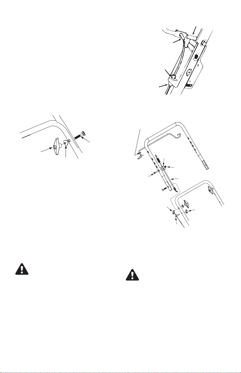
•The blade control handle is a safety device.
Never attempt to bypass its operation.
Doing so makes the safety device inopera-
tive and may result in personal injury
through contact with the rotating blade. The
blade control handle must operate easily in
both directions and automatically return to
the disengaged position when released.
•Never operate the mower in wet grass. Al-
ways be sure of your footing. A slip and fall
can cause serious personal injury. If you
feel you are losing your footing, release the
blade control handle immediately and the
blade will stop rotating within three sec-
onds.
•Mow only in daylight or in good artificial
light. Walk, never run.
•Stop the blade when crossing gravel drives,
walks or roads.
•If the equipment should start to vibrate ab-
normally, stop the engine and check
immediately for the cause. Vibration is gen-
erally a warning of trouble.
•Shut the engine off and wait until the blade
comes to a complete stop before removing
the grass catcher or unclogging the chute.
The cutting blade continues to rotate for a
few seconds after the engine is shut off.
Never place any part of the body in the
blade area until you are sure the blade has
stopped rotating.
•Never operate mower without proper trail
shield, discharge cover, grass catcher,
blade control handle or other safety protec-
tive devices in place and working. Never
operate mower with damaged safety de-
vices. Failure to do so, can result in
personal injury.
•Muffler and engine become hot and can
cause a burn. Do not touch.
•Only use parts and accessories made for
this machine by the manufacturer. Failure to
do so, can result in personal injury.
•If situations occur which are not covered in
this manual, use care and good judgment.
Contact your customer support department.
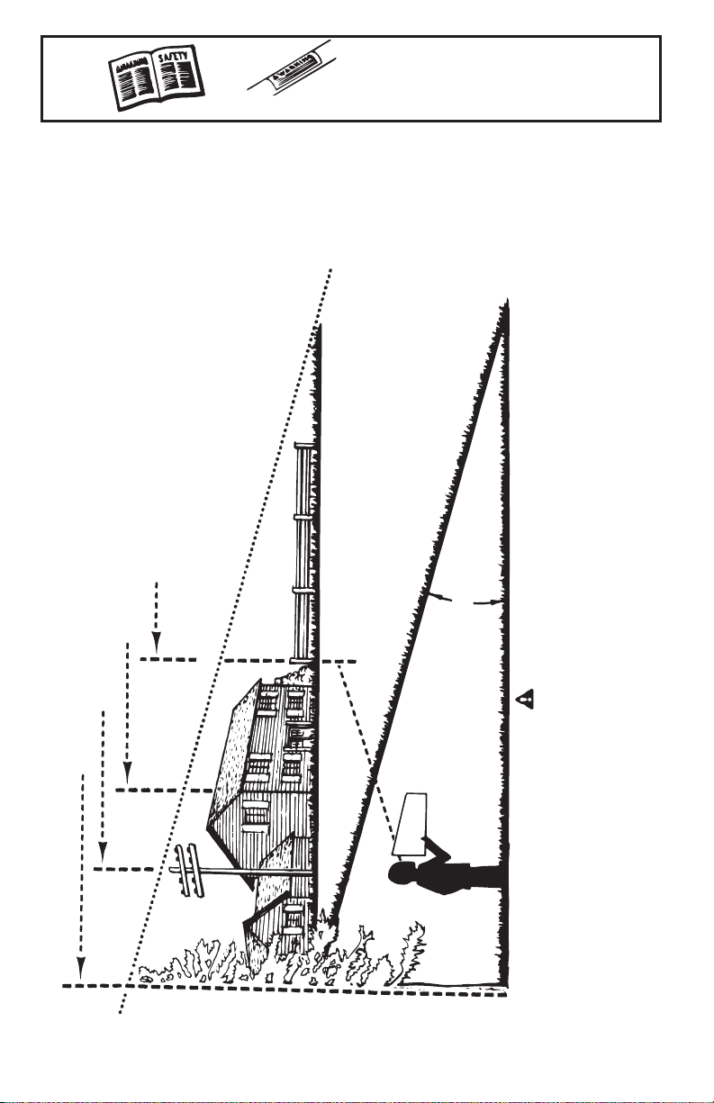
SLOPE OPERATION
Slopes are a major factor related to slip and
fall accidents which can result in severe in-
jury. Operation on slopes requires extra
caution. If you feel uneasy on a slope, do
not mow it. For your safety, use the slope
gauge included as part of this manual to
measure slopes before operating this unit on
a sloped or hilly area. If the slope is greater
than 15 degrees, do not mow it.
DO:
•Mow across the face of slopes; never up
and down. Exercise extreme caution when
changing direction on slopes. Watch for
holes, ruts, bumps, rocks, or other hidden
objects which can cause you to slip or trip.
Tall grass can hide obstacles. Always be
sure of your footing. A slip and fall can
cause serious personal injury. If you feel
you are losing your balance, release the
blade control handle immediately, and the
blade will stop rotating within 3 seconds.
DO NOT:
•Do not mow near drop-offs, ditches or em-
bankments, you could lose your footing or
balance.
•Do not mow slopes greater than 15 degrees
as shown on the slope gauge.
•Do not mow on wet grass. Unstable footing
could cause slipping.
CHILDREN
•Tragic accidents can occur if the operator is
not alert to the presence of children. Children
are often attracted to the mower and the
mowing activity. They do not understand the
dangers. Never assume that children will re-
main where you last saw them.
a) Keep children out of the mowing area
and under the watchful care of a respon-
sible adult other than the operator.
b) Be alert and turn mower off if a child en-
ters the area.
c) Before and while moving backwards,
look behind and down for small children.
d) Use extreme care when approaching
blind corners, doorways, shrubs, trees,
or other objects that may obscure your
vision of a child who may run into the
mower.
e) Keep children away from hot or running
engines. They can suffer burns from a
hot muffler.
•Never allow children under 14 years old to
operate a power mower. Children 14 years
old and over should read and understand
the operation instructions and safety rules in
this manual and should be trained and su-
pervised by a parent.
SERVICE SAFE HANDLING OF GASOLINE:
•To avoid personal injury or property dam-
age use extreme care in handling gasoline.
Gasoline is extremely flammable and the va-
pors are explosive. Serious personal injury
can occur when gasoline is spilled on your-
4

self or your clothes which can ignite. Wash
your skin and change clothes immediately.
a) Use only an approved gasoline con-
tainer.
b) Never fill containers inside a vehicle or
on a truck or trailer bed with a plastic
liner. Always place containers on the
ground away from your vehicle before
filling.
c) When practical, remove gas-powered
equipment from the truck or trailer and
refuel it on the ground. If this is not pos-
sible, then refuel such equipment on a
trailer with a portable container, rather
than from a gasoline dispenser nozzle.
d) Keep the nozzle in contact with the rim
of the fuel tank or container opening at
all times until fueling is complete. Do not
use a nozzle lock-open device.
e) Extinguish all cigarettes, cigars, pipes
and other sources of ignition.
f) Never fuel machine indoors.
g) Never remove gas cap or add fuel while
the engine is hot or running. Allow en-
gine to cool at least two minutes before
refueling.
h) Never over fill fuel tank. Fill tank to no
more than ½ inch below bottom of filler
neck to provide space for fuel expan-
sion.
I) Replace gasoline cap and tighten se-
curely.
j) If gasoline is spilled, wipe it off the engine
and equipment. Move unit to another
area. Wait 5 minutes before starting the
engine.
k) Never store the machine or fuel container
inside where there is an open flame,
spark or pilot light as on a water heater,
space heater, furnace, clothes dryer or
other gas appliances.
l) To reduce fire hazard, keep machine free
of grass, leaves, or other debris
build-up. Clean up oil or fuel spillage
and remove any fuel soaked debris.
m) Allow machine to cool at least 5 minutes
before storing.
GENERAL SERVICE:
•Never run an engine indoors or in a poorly
ventilated area. Engine exhaust contains car-
bon monoxide, an odorless and deadly gas.
•Before cleaning, repairing, or inspecting,
make certain the blade and all moving parts
have stopped. Disconnect the spark plug
wire and ground against the engine to pre-
vent unintended starting.
•Check the blade and engine mounting bolts
at frequent intervals for proper tightness.
Also, visually inspect blade for damage
(e.g., bent, cracked, worn) Replace blade
with the original equipment manufacturer’s
(O.E.M.) blade only, listed in this manual.
“Use of parts which do not meet the original
equipment specifications may lead to im-
proper performance and compromise
safety!”
•Mower blades are sharp and can cut. Wrap
the blade(s) or wear gloves, and use extra
caution when servicing them.
•Keep all nuts, bolts, and screws tight to be
sure the equipment is in safe working con-
dition.
•Never tamper with safety devices. Check
their proper operation regularly.
•After striking a foreign object, stop the en-
gine, disconnect the spark plug wire and
ground against the engine. Thoroughly in-
spect the mower for any damage. Repair
the damage before starting and operating
the mower.
•Grass catcher components, discharge
cover, and trail shield are subject to wear
and damage which could expose moving
parts or allow objects to be thrown. For
safety protection, frequently check compo-
nents and replace immediately with original
equipment manufacturer’s (O.E.M.) parts
only, listed in this manual. “Use of parts
which do not meet the original equipment
specifications may lead to improper perfor-
mance and compromise safety!”
•Do not change the engine governor setting
or overspeed the engine. The governor con-
trols the maximum safe operating speed of
the engine.
•Maintain or replace safety and instruction la-
bels, as necessary.
•Observe proper disposal laws and regula-
tions. Improper disposal of fluids and
materials can harm the environment. SI-102
1.17.02
5

6
15º
USE THIS SHEET AS A GUIDE TO DETERMINE SLOPES WHERE YOU MAY NOT OPERATE SAFELY.
A CORNER OF A BUILDING
FOLD ON DOTTED LINE, REPRESENTING A 15
o
SLOPE
OR A FENCE POST
SIGHT AND HOLD THIS LEVEL WITH A VERTICAL TREE
A POWER POLE
DANGER
Do not mow on inclines with a slope in excess excess of 15 degrees ( a rise of approximately 2½ feet every
10 feet). A riding mower could overturn and cause serious injury. If operating a walk-behind mower on such a
slope, it is extremely difficult to maintain your footing and you could slip, resulting in serious injury.
Operate RIDING mowers up and down slopes, never across the face of slopes.
SLOPE GAUGE
(Keep this sheet in a safe place for future reference.)
OWNER'S
MANUAL
SAFETY LABEL WARNING - Your Responsibility:
Restrict the use of this power machine to persons
who read, understand and follow the warnings and
instructions in this manual and on the machine.

It is suggested that this manual be read in its
entirety before attempting to assemble or
operate. Keep this manual in a safe place for
future reference and for ordering
replacement parts.
This unit is shipped WITHOUT GASOLINE
or OIL. After assembly, service engine with
gasoline and oil as instructed in the separate
engine manual packed with your unit.
Tools Required for Assembly
(1) 3/4" Wrench (2) 7/16" Wrenches
UNPACKING
•Remove the lawn mower and all parts from
the carton. Make certain all parts and litera-
ture have been removed from the carton
before the carton is discarded.
CAUTION: DISCONNECT SPARK
PLUG WIRE. IF THE WIRE IS NOT
EQUIPPED WITH A RUBBER BOOT,
SEE SEPARATE ENGINE MANUAL
FOR GROUNDING PROCEDURE.
CAUTION: DO NOT BEND OR KINK
CONTROL WIRE.
•Refer to "Contents of the Hardware Pack" for
hardware identification, Figure 1.
ATTACHING THE LOWER HANDLE
(Hardware A)
•There is an off-set hole in the lower handle to
provide you with two handle height adjust-
ments. Handles mounted with the notch (see
inset, Figure 2) forward or upward will be
lower then handles mounted with the notch
towards the rear of the unit.
7
Figure 1
CONTENTS OF HARDWARE PACK
Lay out the hardware according to the illustration for identification purposes. Part numbers are
shown in parentheses.
Figure 2
Lower Handle
Handle Mounting
Bracket
Hairpin
Clip
Notch
Hole

•Place the lower handle assembly on the
mower. The holes in the handle fit over the
pins on the deck bracket.
•Secure with cotter pins in the inner holes in
the weld pins. See Figure 2.
ATTACHING THE UPPER HANDLE
(See Hardware B)
•Place the upper handle in position over the
lower handle. The blade control must be on
the upper side of the handle.
•Secure the upper handle to the lower handle
using curved carriage bolts, saddle washers
and large wing nuts, see Figure 3.
NOTE: Wing nuts should be mounted
on the inside
ATTACHING THE CABLES
Brake Control Cable
•The brake cable is attached to the engine,
and has a “Z” fitting on the loose end. Route
the brake cable over the lower handle. Place
end of cable through the hole in the cable
support bracket as shown in Figure 4. Push
the plastic fitting until it locks into the hole.
•Move the blade control handle away from
the upper handle. Hook the “Z” end of the
brake cable into the hole in the blade con-
trol handle from the outside to the inside as
shown in Figure 4.
WARNING: Brake cable must be as-
sembled as shown for proper blade
brake operation.
Drive Control Cable (Hardware F)
•The drive control cable is attached to the
transmission and has a spring on the loose
end. Route the drive around the outside
and above the lower handle so it does not
interfere with attaching the grass bag.
•Hook the spring of the drive cable into the
hole in the lower drive bail handle from the
outside to the inside as shown in Figure 5.
•Secure the support bracket to the upper
handle using hex screw and hex nut, see
Figure 5.
CAUTION: DO NOT BEND OR KINK
CONTROL WIRE.
ATTACHING THE STARTER ROPE
(Hardware C)
•The starter rope is inside the top of the en-
gine. Additional rope may be wound around
the starter handle. If so, unwind the rope from
the handle.
•With the spark plug wire disconnected and
grounded as instructed in the separate engine
manual, hold the blade control handle against
the upper handle and pull the rope out of the
engine.
8
Figure 3
Large
Wing Nut Saddle
Washer
Carriage
Bolt
Figure 4
Hole in
bracket
Plastic Fitting
"Z" Fitting
Blade Control Handle
Figure 5
Hook drive cable
spring here
Hex
Screw
Support
Bracket
Hex Nut
Drive
Cable
Starter Rope
Rope Guide
Small
Wing Nut

•Place the rope guide around the starter han-
dle, so the opening in the rope guide is
toward the front of the mower as shown. In-
sert the rope guide into the right side of the
handle.
•Secure with small wing nut. See Figure 5.
NOTE: If the starter rope becomes dis-
connected from rope guide on handle,
disconnect and ground the spark plug
wire. Depress the blade control handle
and pull the starter rope out from engine
slowly. Slip the starter rope into the
rope guide bolt on handle.
SECURING THE CABLES (Hardware D)
Secure the cable to the left side of the han-
dle as follows.
WARNING: When attaching the con-
trol cables, the cables must be
routed to avoid contact with all
sharp edges and hot surfaces to
prevent damage to the cables,
which will render the control inoper-
ative.
•Insert posts on cable ties into holes pro-
vided on the lower handle. The holes may
be either on the inside or outside of the han-
dles. See Figure 6A.
•Secure the cables with the cable ties. See
Figure 6B. Trim excess ends of cable tie
ASSEMBLY OF CHUTE DEFLECTOR
(Optional) (Hardware F)
•Slide the rod into the upper edge of the
chute deflector so the tab on the rod is to-
ward the left side of the chute deflector.
When assembled correctly, the rod will ex-
tend further to the left side than the right
side. See Figure 7.
•Slide the push nut onto the right side of the
rod to secure.
ATTACHING CHUTE DEFLECTOR TO
MOWER
Lift the rear discharge door con the mower.
Place the ends of the rod into the slots in the
handle bracket assemblies. See Figure 8.
Release the rear discharge door.
To remove the chute deflector, lift the rear
discharge door on the mower. Lift the chute
deflector up, out of the slots in the handle
bracket assemblies. Release the rear dis-
charge door.
CAUTION: Do not run your lawn
mower without chute deflector or an
approved grass catcher in place.
The deflector will deflect a
projectile thrown by the blade into
the lawn.
FINAL ASSEMBLY OF MOWER
Make certain all nuts and bolts are tightened
securely.
ASSEMBLY OF GRASS CATCHER
(Soft Grass Bag)
NOTE: Make certain the grass bag is
turned right side out before assembling
(warning label will be on the outside).
•Join the rear frame and front frame assem-
bly as shown in Figure 9A.
9
AB
Figure 6
Post on
Cable Tie
Figure 8
Rear
Discharge
Door
Slot in Handle
Bracket Assembly
Figure 7
Tab
Chute
Deflector Push
Nut
Rod

•Place bag over frame (black plastic side is
the bottom of bag.) Slip the openings in the
side of the plastic channel on bag over the
hooks on the grass catcher frame.
•Secure bag to frame by working the plastic
channels on bag over frame as shown in
Figure 9B. All of the plastic channels except
center top of bag attach from the outside of
bag. Center top of bag attaches from the in-
side of bag.
ATTACHING GRASS CATCHER TO
MOWER
•Lift the rear discharge door on the mower,
and remove the rear mulching plug. See
Figure 10.
NOTE: Make certain cables are routed
to the outside of the handle so they are
not in the way when attaching the grass
catcher.
•Place the hooks on the grass catcher into
the slots in the handle bracket assemblies.
See Figure 11. Release the rear discharge
door.
TO REMOVE THE GRASS CATCHER
•Lift the rear discharge door on the mower.
Lift the grass catcher up and off the rear
door hinge rod. Release the rear discharge
door.
WARNING: Never operate the
mower unless the hooks on the
grass catcher are seated in the
slots on the handle bracket assem-
blies, and the rear discharge door
rests firmly against the top of the
grass catcher.
CONVERTING TO SIDE DISCHARGE
If your unit is equipped with a side discharge
deflector, you can convert to a side discharge
mower as follows:
•Lift the rear discharge door and install the rear
mulching plug . See Figure 10.
•On the side of the mower deck, lift the hinged
mulching plug. See Figure 12.
•Slide the two hooks on the side discharge de-
flector under the hinge pin on the hinged
mulching plug assembly.
•Lower the hinged mulching plug.
NOTE: Do not remove the hinged mulch-
ing plug at any time, even when you are
not mulching.
WARNING: All mowers are equipped
with a rear protective guard. The
guard helps eliminate projectiles
thrown by the blade from injuring the
operator. DO NOT REMOVE THIS
GUARD.
10
A
B
Figure 9
Rear
Frame
Front
Frame
Assembly
Hook
Plastic
Channels
Bag
Figure 10
Rear
Mulching
Plug
Figure 11
Slot in
Handle
Bracket
Assembly
Rear
Discharge
Door

CONTROLS
BLADE CONTROL HANDLE
WARNING: This control mechanism
is a safety device. Never attempt to
bypass its operations.
The blade control handle is located on the up-
per handle of the mower. See Figure 13. The
blade control handle must be depressed in or-
der to operate the unit. Release the blade
control handle to stop the engine and blade.
WARNING: The blade will be rotating
whenever the engine is running.
RECOIL STARTER
The recoil starter handle is attached to the
handle. See Figure 13. Stand behind the unit
in the operating position to start the unit.
DRIVE CLUTCH CONTROL
Squeezing the drive clutch control engages
the drive system. Releasing the clutch control
disengages the drive system. Release the
clutch control to slow down when negotiating
an obstacle, making a turn or stopping.
OPERATION
Service the engine with gasoline and oil as
instructed in the separate engine manual
packed with your mower. Read instructions
carefully.
WARNING: Never fill fuel tank in-
doors, with engine running or until
the engine has been allowed to cool
for at least two minutes after run-
ning.
BEFORE STARTING
Before each use, check for proper drive
clutch operation by performing the following
before starting the engine:
With the drive clutch control released, push
mower forward. It should move freely.
If it does not and the rear wheels tend to
lock up, the clutch may not be releasing
completely. Do not start the engine until cor-
rections have been made. Check the control
cable for severe bend, kinks and binding, or
grass build-up in the pulley groove. Refer to
the Adjustment section.
•Attach spark plug wire to spark plug. If unit
is equipped with a rubber boot over the end
of the spark plug wire, make certain the
metal loop on the end of the spark plug wire
(inside the rubber boot) is fastened securely
over the metal tip on the spark plug. See
Figure 14.
TO START ENGINE AND ENGAGE BLADE
WARNING: When starting the unit
for the first time, place mower in
first speed (slow) position. Face the
mower against a solid object such
as a wall, fence, etc. Start the unit,
and if it shows any signs of motion
with the drive clutch control disen-
gaged, shut the engine off immedi-
ately. Make certain the drive clutch
control is adjusted so the drive belt
is as loose as possible,. Refer to
the Adjustment Section.
11
Figure 13
Recoil
Starter
Handle
Blade Control
Handle
Drive Clutch
Control
Figure 14
Metal
Loop
on Spark
Plug
Wire Rubber Boot
Figure 12
Hinged Mulching Plug
Side
Chute
Deflector

•If your unit is equipped with a primer, prime
engine as instructed in the separate engine
manual packed with your unit.
•If your unit is equipped with a two speed
control on engine refer to the separate en-
gine manual packed with your unit.
•Standing behind the unit, depress the blade
control handle and hold it against the upper
handle, See Figure 13.
•Grasp the recoil starter handle as shown in
Figure 13 and pull up rapidly. Return it
slowly to the rope guide bolt.
•To engage the drive, squeeze the drive
clutch control handle (see Figure 13) to-
wards the upper handle. Release the drive
clutch control to slow down when negotiat-
ing an obstacle, making a turn, or stopping.
NOTE: The blade control handle must
be depressed in order to operate the
unit. Release the blade control handle
to stop the engine and blade.
TO STOP ENGINE :
•Release the blade control handle to stop the
engine and blade.
•Disconnect and ground the spark plug wire
as instructed in the separate engine manual
to prevent accidental starting while equip-
ment is unattended.
WARNING: The blade continues to
rotate for a few seconds after the
engine is shut off.
FOR THE BEST RESULTS WHEN MULCHING:
Clear lawn of debris. Be sure that the lawn is
clear of stones, sticks, wire or other foreign ob-
jects which could damage the lawnmower. Such
objects could be accidentally thrown out by the
mower in any direction and cause serious per-
sonal injury to the operator and others as well
as damage to property and surrounding objects.
Do not cut wet grass. For effective mulching
do not cut wet grass because it tends to stick to
the underside of the deck preventing proper
mulching of the grass clippings.
Cut no more than 1/3 the length of the grass.
The recommended cut for mulching is 1/3 the
length of the grass. Ground speed will need to
be adjusted so the clippings can be dispersed
evenly into the lawn. For especially heavy cutting
in thick grass it may be necessary to use one of
the slowest speeds in order to get a clean well
mulched cut. When mulching long grass you
may have to cut the lawn in two passes, lower-
ing the blade another 1/3 of the length for the
second cut and perhaps cutting in a different
pattern than was used the first time. Overlapping
the cut a little on each pass will also help to
clean up any stray clippings left on the lawn.
The mower should always be operated at full
throttle to get the best cut and allow it to do the
most effective job of mulching.
Clean underside of deck. Be certain to clean
the underside of the cutting deck after each use
to avoid a build-up of grass, which would pre-
vent proper mulching.
Mulching Leaves. The mulching of leaves can
also be beneficial to your lawn. When mulching
leaves make sure they are dry and are not lay-
ing too thick on the lawn. Do not wait for all the
leaves to be off the trees before you mulch.
It is recommended keeping driveways and side-
walks on the operators right while moving.
Continue mowing using this pattern, having the
left side of your lawnmower next to the uncut
grass. Mulching with the cutting area of the
mower on the lawn avoids grass clippings in un-
desirable areas.
WARNING: If you strike a foreign ob-
ject, stop the engine. Remove wire
from spark plug, thoroughly inspect
the mower for any damage, and repair
the damage before restarting and op-
erating the mower. Extensive vibration
of the mower during operation is an
indication of damage. The unit should
be promptly inspected and repaired.
DECK
The underside of the mower deck should be
cleaned after each use to prevent a buildup of
grass clippings, leaves, dirt or other matter. If
this debris is allowed to accumulate, it will invite
rust and corrosion, and may prevent proper
mulching.
The deck may be cleaned by tilting the mower
and scraping clean with a suitable tool (make
certain the spark plug wire is disconnected).
ADJUSTMENT
CAUTION : DO NOT AT ANY TIME
MAKE ANY ADJUSTMENT TO
LAWNMOWER WITHOUT FIRST
STOPPING THE ENGINE AND
DISCONNECTING THE SPARK
PLUG WIRE
MODELS WITH NINE POSITION HEIGHT
ADJUSTERS: (See Figure 15).
•Stop mower and disconnect spark plug cable
before changing mower cutting height.
12

•The wheel adjusters give you nine (9) different
cutting positions. Medium is the best for most
mowers.
•To change the height of cut, squeeze adjuster
lever toward the wheel, moving up or down to
selected height.
NOTE: All wheels must be in the
same height of cut.
•When cutting in heavy or moist grass, the rear
of lawnmower may be raised higher to allow
better discharge of the grass.
HANDLE HEIGHT ADJUSTMENT
Your mower is shipped with the handle in
the higher height position. To lower the han-
dle height, proceed as follows.
•Remove the starter rope and the rope guide.
•Remove the upper handle by removing the
handle knobs and carriage bolts. Lay the
upper handle out of the way, being careful
not to bend or kink the cables.
•Remove the hairpin clips from the weld pins
on the handle brackets. Press out on the
legs of the lower handle. Remove lower
handle from the mower.
•Turn the lower handle around so the notch
on the bottom of the lower handle is facing
forward as shown in Figure 2. Reassemble,
placing the bottom holes in the handle over
the weld pins in the handle mounting
bracket.
•Reassemble the upper handle to the lower
handle.
•Place the hairpin clips in the inner holes in
the weld pins and attach the starter rope
and rope guide as instructed in the “Set-Up”
section of this manual.
LUBRICATION
CAUTION: DISCONNECT SPARK
PLUG WIRE BEFORE SERVICING
WHEELS - Lubricate the ball bearings in
each wheel at least once a season with a
light oil. Also, if the wheels are removed for
any reason, lubricate the surface of the axle
bolt and the inner surface of the wheel with
light oil. Engine oil may also be used.
ENGINE - Follow engine manual for lubrica-
tion instructions.
BLADE CONTROL - Lubricate the pivot
points on the blade control handle and the
brake cable at least once a season with light
oil. The blade control must operate freely in
both directions.
REAR and SIDE DISCHARGE DOORS -
The torsion springs and pivot points should
be lubricated periodically with light oil to pre-
vent any rust or binding. Door must work
freely.
TRANSMISSION - The transmission is
pre-lubricated and sealed at the factory and
does not require lubrication on a regular ba-
sis as part of maintenance. However, if you
disassemble the transmission for any reason,
refill with two ounces of Alvania grease (part
number 737-0168) as part of reassembly.
MAINTENANCE
For best results your blade should be sharp.
The blade may be resharpened by removing it
and either grinding or filing the cutting edge
keeping as close to the original bevel as possi-
ble.
Improper blade balance will result in excessive
vibration causing eventual damage to the en-
gine and mower. Be sure to carefully balance
blade after sharpening.
After prolonged use, especially in sandy soil
conditions, the blade will become worn and
lose some of the original shape. Cutting effi-
ciency will be reduced and the blade should be
replaced. Replace with an approved factory re-
placement blade only. Possible damage
resulting from blade unbalance condition is not
the responsibility of the manufacturer.
NOTE: Tip mower as specified in sep-
arate engine manual. If not specified
tip with carburetor up.
CUTTING BLADE
CAUTION: Cutting grass in sandy
soil condition causes abrasive wear
to the blades.
When removing the cutting blade for sharpen-
ing or replacement, protect hands by using
heavy gloves or a rag to grasp the cutting
blade.
13
Figure 15

•Remove the bolt and bell washer which hold
the blade-pulley assembly to the engine crank-
shaft. Remove the assembly from the
crankshaft.
•Remove the two bolts and lock nuts from the
assembly and remove the blade from the
blade adaptor and pulley.
•Before reassembling the blade-pulley as-
sembly to the unit, lubricate the engine
crankshaft and the inner surface of the blade
adapter with light oil (or engine oil). Lubri-
cating the bolt holes, bolts and inner surface
of the nuts is also recommended.
Installing the blade
•Install the pulley over the blade adapter with
the “star” away from the pulley. Refer to Figure
16.
•Place the blade on the
adapter with the side of
he blade marked bot-
tom (or with part
number) facing away
from the adapter.
•Secure the blade to the assembly with two
hex bolts and lock nuts. Tighten the hex
bolts to the torque listed in the “Blade
Mounting Torque” Section below.
•Install the blade assembly up on the crank-
shaft. Secure with the hex bolt and cupped
washer (cupped side of washer to blade) and
tighten to torque listed in the “Blade Mounting
Torque” section below.
IMPORTANT: The bolt, used to secure the
blade to the engine, is especially
heat-treated. Do not substitute. To order re-
placement bolt, refer to the parts listed in the
middle of this manual.
Blade Mounting Torque
Blade Adapter Bolts:120 in. lbs. min., 150 in.
lbs. max.
Center Bolt: 450 in. lbs. min., 600 in. lbs.
max.
To ensure safe operation of your unit, all
nuts and bolts must be checked periodically
for correct tightness.
ENGINE
Refer to the separate engine manual for engine
maintenance instructions.
Maintain engine oil as instructed in the separate
engine manual packed with your unit. Read
and follow instructions carefully.
Service air cleaner as per separate engine
manual under normal conditions. Clean every
few hours under extremely dusty conditions.
Poor engine performance and flooding usually
indicates that the air cleaner should be ser-
viced. To service the air cleaner, refer to the
separate engine manual packed with your unit.
The spark plug should be cleaned and the gap
reset once a season. Spark plug replacement
is recommended at the start of each mowing
season; check engine manual for correct plug
type and gap specifications.
NOTE: This spark ignition system meets
all requirements of the Canadian Interfer-
ence-Causing Equipment Regulations.
Clean the engine regularly with a cloth or
brush. Keep the cooling system (blower hous-
ing area) clean to permit proper air circulation
which is essential to engine performance and
life. Be certain to remove all grass, dirt and
combustible debris from muffler area.
REAR FLAP REPLACEMENT
The rear flap is attached to the back of the
mower deck, and is designed to minimize the
possibility that objects will be thrown from the
rear of the mower toward the operator. If the
rear flap becomes damaged, replace as fol-
lows.
To remove the old rear flap, cut off the flat end
of the wire rod which secures it to the deck us-
ing a pair of side-cutters. Attach the new rear
flap using the new rod provided with the rear
flap, bending the ends of the rod over to secure.
BELT REMOVAL AND REPLACEMENT
•Remove two shoulder screws securing the front
drive cover to the mower deck. See Figure 17.
•Press inward on the sides of the front drive
cover and release the tabs that secure the
front drive cover to the height adjuster
14
Figure 16
Hex Bolt
Cupped
Washer
Hex Bolt
Hex Bolt
Blade
Blade
Adapter
Pulley
Assembly
Locknut Locknut
Crowned
Side
Cupped
Side

brackets. Remove drive cover from the
mower.
•Using a torx wrench, loosen the screw hold-
ing the belt tension spring to the
transmission. See Figure 17. Do not remove
the screw completely. As you loosen the
screw, the tension on the belt will be re-
leased.
•Push the transmission up a little and slide
the belt off the transmission pulley.
•Lift the mower to access the belt from the
underside of the mower.
•Slide the belt off the engine pulley and
around the blade. See Figure 18.
•Replace with the new belt, working around
the blade. Make sure the belt is firmly
seated on the engine pulley while pulling
from the other side and sliding it around the
transmission pulley.
•Put the mower down with all four wheels
firmly placed on one level.
•Tighten the screw, loosened earlier, to se-
cure the belt tension spring to the
transmission, and reassemble the front drive
cover.
OFF SEASON STORAGE
INSTRUCTIONS
The following steps should be taken to pre-
pare lawn mower for storage.
•Clean and lubricate mower thoroughly as
described in the lubrication instructions.
•Refer to engine manual for correct engine
storage instructions.
•Coat mower’s cutting blade with chassis
grease to prevent rusting.
•Store mower in a dry, clean area.
NOTE: When storing any type of power
equipment in an unventilated or metal
storage shed, care should be taken to
rust-proof the equipment. Using a light
oil or silicone, coat the equipment, es-
pecially cables and all moving parts.
NOTE: Be careful not to bend or kink
cables.
NOTE: If the starter rope becomes dis-
connected from rope guide on handle,
disconnect and ground the spark plug
wire. Depress the blade control handle
and pull the starter rope out from en-
gine slowly. Slip the starter rope into
the rope guide bolt on handle.
15
Figure 17
Loosen this nut.
Drive
Belt
Front Drive
Cover
Shoulder
Screw
Transmission
Shoulder
Screw
Figure 18
Right
Front
Wheel
Left
Front
Wheel
Remove belt from around
pulley and blade
Engine
Pulley

16
REPLACEMENT PARTS/PIÈCES DÉTACHÉES
For models with 8" rear wheels/
Pour modèles à pneu arrière de 8 po

REF PART
NO. NO.
N° DE N° DE
RÉF PIÈCE DESCRIPTION DESCRIPTION
1 747-2136 Lower Bail Handle Étier de suspension-inférieur
2 747-0824 Control Lever Barre de commande
2 647-0004 Control Handle Guidon de la commande
3 749-1230A-637 Upper Handle Guidon-supérieur
4 710-1270 Oval C-Sunk Scr 1/4-20 X 1.31" Lg. Vis à tête noyée 1/4-20 X 1,31 po de lg.
5 746-0883 Cable Housing Logement du câble
6 712-0324 Hex Ins. Locknut 1/4-20 Gr. 8 Nylon Écrou hex. 1/4-20 Qte 8 nylon
7 746-0551 Control Cable 43" Black Câble de la commande 43 po noir
7 746-0555 Control Cable 55" Orange Câble de la commande 55 po orange
8 749-0928A-637 Lower Handle Guidon-inférieur
9 746-04026 Drive Cable Câble d’entraînement
10 710-0606 Hex Scr 1/4-20 X 1.50 Vis à tête hexagonale 1/4-20 X 1,50
11 710-1174 Carriage Bolt 5/16-18 x 2.0 Boulon ordinaire 5/16-18 x 2.0
12 720-0284 Wingnut Knob, 5/16-18 Bouton 5/16-18
13 736-0451 Saddle Wash. .320 ID X .93 OD Rondelle selle ,320 DI X ,93 DE
14 720-0279 Knob - ERS Guide 1/4-20 Bouton - 1/4-20
15 710-1205 Rope Guide Bolt Boulon de guidage de cordon
16 782-5004A Right Rear Baffle Deflecteur de arriere droit
17 712-0431 Flanged Lock Nut Ecrou de blocage
18 631-0075B Engine Spacer Assembly Entretoise de la moteur
23 714-0104 Int. Cotter Pin .072 X 1.13" Lg. Goupille fendue ,072 X 1,13 po. de lg.
24 731-1236 Rear Flap 17.69 Abattant de protection arrière 17.69
25 732-0700 Wire Fil
26 720-0275 Knob Bouton
27 710-0192 Truss Mach Scr #10-24 X .38 Vis de renforcement usinée no 10-24 X .38
28 732-0677 LH Torsion Spring Ressort de torsion CG
29 782-5003A Left Rear Baffle 21" Côté de la goulotte arriere gauche 21 po
30 710-1017 Torx Mach. Scr. 1/4-14 X .625" Vis torx AB 1/4-14 X ,625 po de lg
31 732-0678 RH Torsion Spring Ressort de torsion CD
32 710-0896 Hex Wash Scr 1/4-14 X .625 Vis taraudée 1/4-14 x 0,625
33 720-0426 Knob Bouton
34 736-0105 Bell. Wash .375 ID X .870 OD X .063 Rondelle Bell ,375 DI X ,870 DE X ,063
35 634-0020 Wheel Assembly 8 x 1.75 Ensemble de roue 8 x 1.75
734-1978 Wheel Assembly8x2(Ball Brg) Ensemble de roue 8 x 2.0 (roulement à
billes)
36 738-0102 Axle Bolt Boulon de l’essieu
37 720-0249 Hub Cap - Grey Moyeu de chapeau - gris
37 731-0981A Hub Cap Grey Radial Moyeu de chapeau - gris
38 682-0513 Handle Brkt. Ass’y -LH Support du guidon - gauche
38 682-0514 Handle Brkt. Ass’y -RH Support du guidon -droite
39 14766 Pivot Bar LH SP Barre de pivot - Gauche
39 14765 Pivot Bar RH SP Barre de pivot - Droit
40 732-0706 Spring Lever RH Levier de ressort CD
40 732-0707 Front Lever LH Levier de ressort-CG
41 738-0507B Shoulder Screw .50 Dia. Vis à épaulement .50 Dia.
42 726-0240 Cable Tie Attache caâble
43 720-0294 Foam Grip Poignée
44 712-0431 Hex Nut 3/8-16 Gr. 2 Écrou hex 3/8-16 Qté. 2
45 736-0356 Bell. Washer .38 ID X 1.38 OD X .06 Rondelle Bell. .38 DI X 1.38 DE X .06
46 732-1043 Belt Tension Spring Ressort de tension de la courroie
47 782-0080A Rear Discharge Deck 21" Corps 21 po.
48 754-0637 V-Belt 3/8 X 35.68" Courroie trapezoïdale 3/8 X 35,68 po
49 731-1404A Mulching Plug Obturateur de dechiquetage
50 751B224437 Muffler Guard (Quantum Only) Déflecteur de silencieux (Quantum seul.)
51 751B224511 Flywheel Guard (Quantum/Intek only) Déflecteur du volant du moteur
(Quantum/Intek)
53 782-5002A Front Baffle 21" Côté de la goulotte arrière
54 618-0657 Transmission Assembly Complete Transmission complet
55 7510042824 Screw #12 x .457 Vis no. 12 x .457
56 731-2600 Front Drive Cover-Yellow Couvercle-jaune
Continued on next page/Suite à la page prochaîne
17

REF PART
NO. NO.
N° DE N° DE
RÉF PIÈCE DESCRIPTION DESCRIPTION
56 731-1937A Front Drive Cover-Black Couvercle-noir
57 715-0169 Roll Pin Goupille-ronde
58 736-0331 Bell. Washer .39 ID x 1.12 OD12 OD Rondelle Bell. .39 DI X 1.12 DE
59 748-0355 Bearing Support Support du roulement
60 736-0447 Wave Washer Rondelle ondulee
61 782-0511A Height Adj. Plate LH Réglage de hauteur-plaque CG
61 782-0512B Height Adj. Plate RH Réglage de hauteur-plaque CD
62 682-0509 Height Adj. Pivot Plate Ass’y Pivot du plaque -réglage de hauteur
63 756-1146A Drive Pulley Poulie d’entraînement
64 748-0411 Blade Adapter Adaptateur de lame
65 742-0741 21" Mulching Blade Lame dechiquetage 21 po
65 742-0641 Standard Blade 21" Lame ordinaire 21 po.
66 712-0324 Hex Ins. Locknut 1/4-20 Gr. 8 Nylon Écrou hex. 1/4-20 Qté 8 nylon
67 710-0216 Hex Cap Screw 3/8-16 X .75 Vis à chapeau à six pans de 3/8-16 X .75
68 715-0221 Pin Goupille
69 717-1762 Spur Gear 14T RH Engrenage 14 dents droite
69 717-1761 Spur Gear 14T LH Engrenage 14 dents gauche
70 714-0101 Internal Cotter Pin Goupille fendue - Int.
71 736-3013 Flat Washer .53 x 1.0 x .03 Rondelle plate .53 x 1.0 x .03
72 716-0865 Snap Ring .50 Dia. Joint ,50 Dia.
73 782-7551 Wheel Dust Cap Cache-poussiere
74 716-0102 Snap Ring for 1.0" shaft Jonc d’arrêt pour arbre 1.0 PO
75 736-0474 Flat Washer ‘DD’ 1.5 OD x .03 Rondelle plate 1.5 DE x .03
76 756-1231 Input Pulley Poulie puissance
77 710-1257 Hex Bolt 3/8-24 x 2.5" Lg. Boulon hex. 3/8-24 c 2.5 po de lg.
78 736-0452 Belleville Washer .396 X 1.14 X .095 Rondelle Belleville ,396 X 1,14 X ,095
82 750-1166 Sleeve Spacer LH Entretoise CG
82 750-1165 Sleeve Spacer RH Entretoise CD
83 682-0516A Handle Brkt Ass'y RH Comp. Support du poignée-droit
84 682-0515A Handle Brkt Ass''ly LH Comp. Support du poignée-gauche
85 782-7000 RB Chute Door Porte de goulotte
86 731-2623 Bail Cover Couvercle-guidon de commande de la lame
87 732-0731 Torsion Spring Ressort de torsion
88 732-0417A Spring Lever SP Ressort de levier
89 710-1008 Hex L-Wash TT Scr. 3/8-16 X 1.875 Vis taraudee 3/8-16 X 1.875
90 682-0512A Height Adj. Assembly RH Complete Réglage de hauteur complet-CD
91 682-0511A Height Adj. Assembly LH Complete Réglage de hauteur CG complet
92 710-1248 Weld Pin Goupille à soudure
93 634-0021C Wheel8X2X1.75 Ensemble de roue8X2X1,75
734-1983A Wheel 8 x 2 (Link/Ball Brg) Ensemble de roue8x2(Link/roulement à
billes)
94 764-0310 Rear Catcher Frame Tube Tuyau du bâti du sac récuperateur
95 782-9011 Hardtop Mounting Bracket Support du montage
96 710-0286 Truss Mach Scr 1/4-20 X .50 Vis de renforcement à tête cintrée 1/4-20 X
.50
97 712-0324 Hex Ins. Locknut 1/4-20 Gr. 8 Nylon Écrou hex. 1/4-20 Qté 8 nylon
98 731-1322A Hardtop Cover w/o Logo: Black Couvercle-noir (sans logotype)
98 731-1876 Hardtop Cover w/Logo: Black Couvercle-noir (avec logotype)
98 764-0433 Grassbag for Hardtop Assembly Sac récuperateur
99 764-0476A Grass Bag: Soft Top w/Logo Sac récuperateur (avec logotype)
99 764-0309 Grass Bag: Soft Top w/o Logo Sac récuperateur (sans logotype)
100 782-5007A Mulching Plug Déflecteur de dechiquetage
101 726-0201 Push Speed Nut Écrou rapide d’enfoncer
102 711-0996 Rod Tige
103 731-1405 Side Discharge Adapter Adapteur-goulotte à èjection
104 764-0311 Catcher Lower Frame Sac récuperateur - bâti infèrieur
105 190-104-000 Chute Deflector Complete Goulotte à éjection complet
440-450
12.19.02
18

19
Engine Shroud Chart
NOTE: This chart shows all the optional engine shrouds for the lawn mowers covered in this
manual. To order replacement parts, please refer to the shroud and hardware applicable to
your lawn mower unit.
Tableau des capots de moteur
REMARQUE : Ce tableau représente tous les capots en option proposés pour les tondeuses
mentionnées dans cette notice. Pour commander un capot de rechange, veuillez indiquer le
capot et la quincaillerie correspondant à votre modèle de tondeuse.
* Part No./Node pièce
** Colour/Couleur
*
**
751B281439
Dark Red/Rouge foncé
751B281440
Black/Noir
*
**
731-1395A
Red/Rouge
731-1396A
***
731-1402A Yellow/Jaune
731-1694 Black/Noir
731-1695 Silver/Argent
731-1394 Charcoal/Charbon de
bois
***
731-1585B Black/Noir
*** 710-1274
***
7510143208 Black/Noir
*** 7510042823
***
731-1586B Black/Noir
731-1612A Red/Rouge
***
7511681311 Black/Noir
7511681911 Red/Rouge
7511682011 Grey/Gris
***
751B281451 Grey/Gris
*** 710-1256
***
751B281476 Black/Noir
751B281777 Yellow/Jaune

TWO YEAR LIMITED WARRANTY
For TWO YEARS from the date of retail purchase within Canada, MTD PRODUCTS
LIMITED will, at its option, repair or replace, for the original purchaser, free of charge, any
part or parts found to be defective in material or workmanship.
This warranty does not cover:
1. Any part which has become inoperative due to misuse, commercial
use, abuse, neglect, accident, improper maintenance or alteration; or
2. The unit if it has not been operated and/or maintained in accordance
with the owner’s instructions furnished with the unit; or
3. The engine or motor or component parts thereof which carry separate
warranties from their manufacturers. Please refer to the applicable
manufacturer’s warranty on these items; or
4. Batteries and normal wear parts except as noted below. Log splitter
pumps, valves and cylinders or component parts thereof are covered
by a one year warranty; or
5. Routine maintenance items such as lubricants, filters, blade sharpening
and tune-ups, or adjustments such as brake, clutch or deck; or
6. Normal deterioration of the exterior finish due to use or exposure.
Full Ninety Day Warranty on Battery: For ninety (90) days from the date of retail pur-
chase, if any battery included with this unit proves defective in material or workmanship
and our testing determines the battery will not hold a charge, MTD PRODUCTS LIMITED
will replace the battery at no charge to the original purchaser.
Additional Limited Thirty Day Warranty on Battery: After ninety (90) days but within
one hundred twenty (120) days from the date of purchase, MTD PRODUCTS LIMITED will
replace the defective battery, for the original purchaser, for a cost of one-half (1/2) of the
current retail price of the battery in effect at the date of return.
Full Sixty Day Warranty on Normal Wear Parts: Normal wear parts are defined as belts,
blade adapters, blades, grass bags, seats, tires, rider deck wheels and clutch parts (fric-
tion wheels). These parts are warranted to the original purchaser to be free from defects
in material and workmanship for a period of sixty (60) days from the date of retail pur-
chase.
How to Obtain Service: Warranty service is available, with proof of purchase, through
your local authorized service dealer or distributor. If you do not know the dealer or dis-
tributor in your area, please call, toll free 1-800-668-1238. The return of a complete unit
will not be accepted by the factory unless prior written permission has been extended by
MTD PRODUCTS LIMITED.
Transportation Charges: Transportation charges for the movement of any power equip-
ment unit or attachment are the responsibility of the purchaser. Transportation charges
for any part submitted for replacement under this warranty must be paid by the purchaser
unless such return is requested in writing by MTD PRODUCTS LIMITED.
Other Warranties: All other warranties, express or implied, including any implied war-
ranty of merchantability is limited in its duration to that set forth in this express limited
warranty. The provisions as set forth in this warranty provide the sole and exclusive rem-
edy of MTD PRODUCTS LIMITED obligations arising from the sale of its products.
MTD PRODUCTS LIMITED will not be liable for incidental or consequential loss or dam-
age.
20
Table of contents
Languages:
Other MTD Lawn Mower manuals

MTD
MTD Bolens 13AP616H565 User manual

MTD
MTD 112-638A User manual

MTD
MTD 122-250 User manual

MTD
MTD 11A-54MY229 User manual

MTD
MTD 190-800-000 User manual

MTD
MTD AutoDrive 13AU604H402 User manual

MTD
MTD 030 thru 062 User manual

MTD
MTD 549 Series User manual

MTD
MTD Series A4 User manual

MTD
MTD 134-395-000 User manual