MTD Cub Cadet 221 HP User manual

Professional Shop Manual
221 HP/LHP Snow Throwers
NOTE: These materials are for use by trained technicians who are experienced in the service and repair of outdoor power
equipment of the kind described in this publication, and are not intended for use by untrained or inexperienced individuals.
These materials are intended to provide supplemental information to assist the trained technician. Untrained or inexperi-
enced individuals should seek the assistance of an experienced and trained professional. Read, understand, and follow all
instructions and use common sense when working on power equipment. This includes the contents of the product’s Oper-
ators Manual, supplied with the equipment. No liability can be accepted for any inaccuracies or omission in this publication,
although care has been taken to make it as complete and accurate as possible at the time of publication. However, due to
the variety of outdoor power equipment and continuing product changes that occur over time, updates will be made tothese
instructions from time to time. Therefore, it may be necessary to obtain the latest materials before servicing or repairing a
product. The company reserves the right to make changes at any time to this publication without prior notice and without
incurring an obligation to make such changes to previously published versions. Instructions, photographs and illustrations
used in this publication are for reference use only and may not depict actual model and component parts.
© Copyright 2011 MTD Products Inc. All Rights Reserved


I
Chapter 1: Introduction ......................................................................................................1
Professional Service Manual Intent . . . . . . . . . . . . . . . . . . . . . . . . . . . . . . . . . . . . . .1
Safety . . . . . . . . . . . . . . . . . . . . . . . . . . . . . . . . . . . . . . . . . . . . . . . . . . . . . . . . . . . . .1
Fasteners . . . . . . . . . . . . . . . . . . . . . . . . . . . . . . . . . . . . . . . . . . . . . . . . . . . . . . . . . .3
Assembly instructions. . . . . . . . . . . . . . . . . . . . . . . . . . . . . . . . . . . . . . . . . . . . . . . . 3
Description of the High Performance Single Stage Snow Thrower. . . . . . . . . . . . . 3
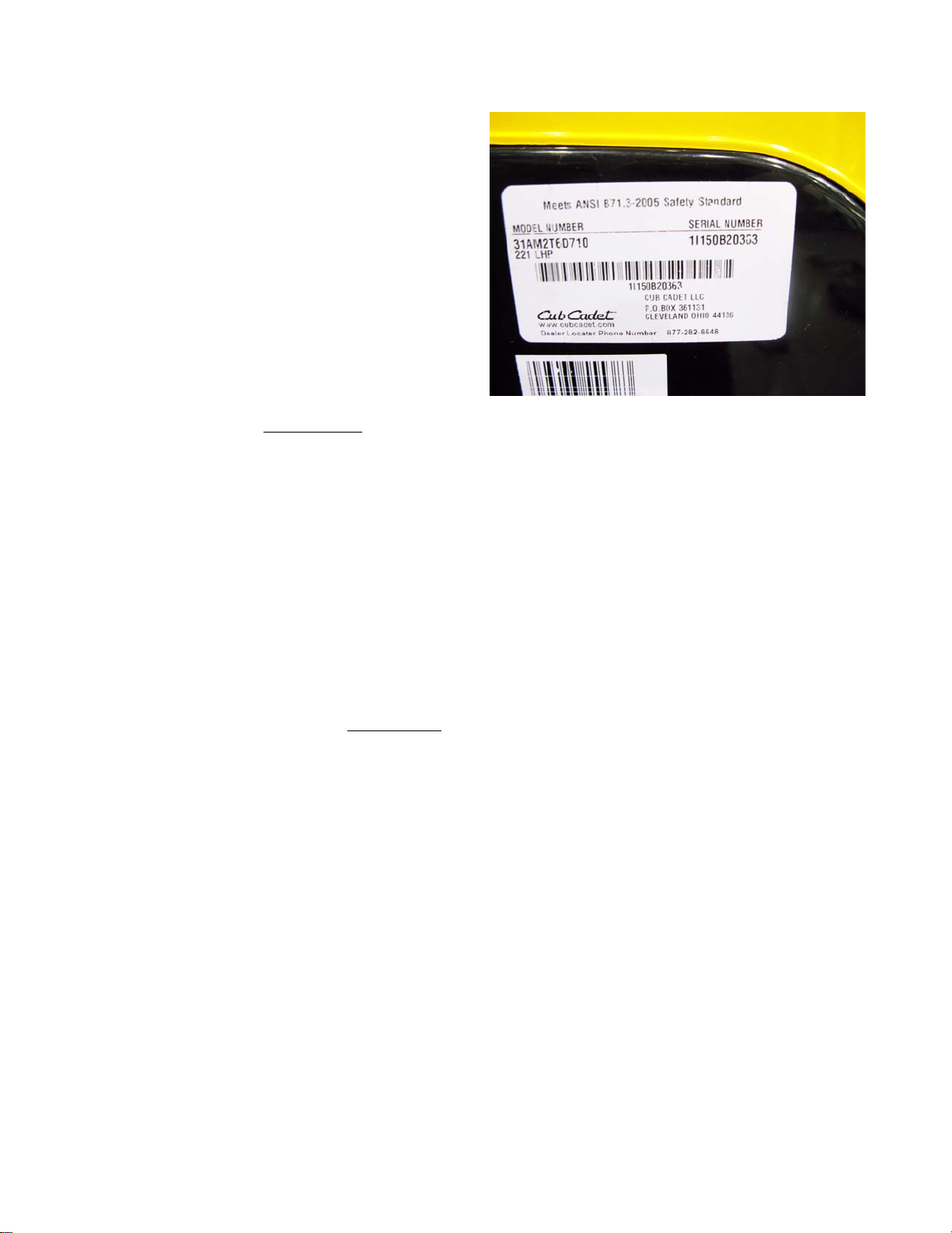
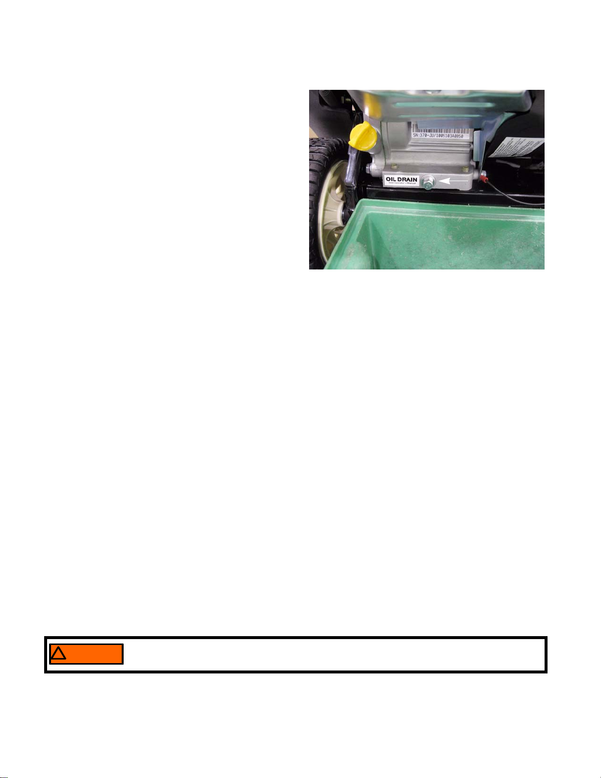
Understanding model and serial numbers . . . . . . . . . . . . . . . . . . . . . . . . . . . . . . . . 4
Chapter 2: Engine................................................................................................................ 5
Maintenance . . . . . . . . . . . . . . . . . . . . . . . . . . . . . . . . . . . . . . . . . . . . . . . . . . . . . . . .5
Spark plugs . . . . . . . . . . . . . . . . . . . . . . . . . . . . . . . . . . . . . . . . . . . . . . . . . . . . . . . .5
Oil change . . . . . . . . . . . . . . . . . . . . . . . . . . . . . . . . . . . . . . . . . . . . . . . . . . . . . . . . .6
Fuel . . . . . . . . . . . . . . . . . . . . . . . . . . . . . . . . . . . . . . . . . . . . . . . . . . . . . . . . . . . . . .6
Valve lash . . . . . . . . . . . . . . . . . . . . . . . . . . . . . . . . . . . . . . . . . . . . . . . . . . . . . . . . .7
Rear engine cover . . . . . . . . . . . . . . . . . . . . . . . . . . . . . . . . . . . . . . . . . . . . . . . . . . .9
Top engine cover . . . . . . . . . . . . . . . . . . . . . . . . . . . . . . . . . . . . . . . . . . . . . . . . . . .10
Fuel tank . . . . . . . . . . . . . . . . . . . . . . . . . . . . . . . . . . . . . . . . . . . . . . . . . . . . . . . . .13
Engine removal . . . . . . . . . . . . . . . . . . . . . . . . . . . . . . . . . . . . . . . . . . . . . . . . . . . .14
Maintenance charts . . . . . . . . . . . . . . . . . . . . . . . . . . . . . . . . . . . . . . . . . . . . . . . . .16
Chapter 3: Auger, Belt And Pulleys .................................................................................17
Belt . . . . . . . . . . . . . . . . . . . . . . . . . . . . . . . . . . . . . . . . . . . . . . . . . . . . . . . . . . . . . .17
Auger pulley . . . . . . . . . . . . . . . . . . . . . . . . . . . . . . . . . . . . . . . . . . . . . . . . . . . . . .18
Engine pulley . . . . . . . . . . . . . . . . . . . . . . . . . . . . . . . . . . . . . . . . . . . . . . . . . . . . . .19
Idler pulley and idler arm . . . . . . . . . . . . . . . . . . . . . . . . . . . . . . . . . . . . . . . . . . . .20
Rubber auger spiral replacement . . . . . . . . . . . . . . . . . . . . . . . . . . . . . . . . . . . . . . .22
Auger . . . . . . . . . . . . . . . . . . . . . . . . . . . . . . . . . . . . . . . . . . . . . . . . . . . . . . . . . . . 23
Auger bearings . . . . . . . . . . . . . . . . . . . . . . . . . . . . . . . . . . . . . . . . . . . . . . . . . . . . .24
Control cable . . . . . . . . . . . . . . . . . . . . . . . . . . . . . . . . . . . . . . . . . . . . . . . . . . . . . .26
Chapter 4: Auger Housing Components ......................................................................... 27
Shave plate . . . . . . . . . . . . . . . . . . . . . . . . . . . . . . . . . . . . . . . . . . . . . . . . . . . . . . . .27
Upper discharge chute (manual) . . . . . . . . . . . . . . . . . . . . . . . . . . . . . . . . . . . . . . .27
Upper discharge chute (remote controlled) . . . . . . . . . . . . . . . . . . . . . . . . . . . . . . .28
Lower discharge chute . . . . . . . . . . . . . . . . . . . . . . . . . . . . . . . . . . . . . . . . . . . . . . .30
Chute ring gear (manual) . . . . . . . . . . . . . . . . . . . . . . . . . . . . . . . . . . . . . . . . . . . . .31
Chute rotating gears (joy stick) . . . . . . . . . . . . . . . . . . . . . . . . . . . . . . . . . . . . . . . .32
Joy stick . . . . . . . . . . . . . . . . . . . . . . . . . . . . . . . . . . . . . . . . . . . . . . . . . . . . . . . . . .36
Testing the joy stick . . . . . . . . . . . . . . . . . . . . . . . . . . . . . . . . . . . . . . . . . . . . . . . . .36
Rebuilding the joy stick . . . . . . . . . . . . . . . . . . . . . . . . . . . . . . . . . . . . . . . . . . . . . .37
Upper discharge chute pitch control cables and lever . . . . . . . . . . . . . . . . . . . . . . 38
Left side panel . . . . . . . . . . . . . . . . . . . . . . . . . . . . . . . . . . . . . . . . . . . . . . . . . . . . .40
Right side panel . . . . . . . . . . . . . . . . . . . . . . . . . . . . . . . . . . . . . . . . . . . . . . . . . . . .41
Auger housing . . . . . . . . . . . . . . . . . . . . . . . . . . . . . . . . . . . . . . . . . . . . . . . . . . . . .42
Table of Contents

II

Introduction
1
Professional Service Manual Intent
This Manual is intended to provide service dealers with an introduction to the mechanical aspects of the Cub
Cadet high performance single stage snow throwers.
Disclaimer: The information contained in this manual is correct at the time of writing. Both the product and the infor-
mation about the product are subject to change without notice.
About the text format:
NOTE: is used to point out information that is relevant to the procedure, but does not fit as a step in the proce-
dure.
• Bullet points: indicate sub-steps or points.
1. Numbered steps indicate specific things that should be done, and the order in which they should be done.
1a. Substeps will be lettered and nested within steps. Two or more substeps may be combined to describe
the actions required to complete a step.
Disclaimer: This manual is intended for use by trained, professional technicians.
• Common sense in operation and safety is assumed.
• In no event shall MTD or Cub Cadet be liable for poor text interpretation or poor execution of the proce-
dures described in the text.
• If the person using this manual is uncomfortable with any procedures they encounter, they should seek
the help of a qualified technician or Cub Cadet Technical Support.
Safety
This Service Manual is meant to be used along with the Operator’s Manual. Read the Operator’s Manual and
familiarize yourself with the safety and operational instructions for the equipment being worked on. Keep a copy of
the Operator’s Manual for quick reference. Operator’s manuals may be viewed for free at the Cub Cadet website. It
will be necessary to have the complete model and serial number for the equipment.
Caution is used to point out potential danger to the technician, operator, bystanders, or sur-
rounding property.
! CAUTION! CAUTION
Warning indicates a potentially hazardous situation that, if not avoided, could result in death
or serious injury.
! WARNING! WARNING
! DANGER! DANGER Danger indicates an imminently hazardous situation that, if not avoided, will result in death or
serious injury. This signal word is to be limited to the most extreme situations
CHAPTER 1: INTRODUCTION

221 HP/LHP
2
• Be prepared in case of emergency:
Keep a fire extinguisher nearby
Keep a first aid kit nearby
Keep emergency contact numbers handy
• Replace any missing or damaged safety labels on shop equipment.
• Replace any missing or damaged safety labels on equipment being serviced.
! CAUTION! CAUTION
• Grooming and attire:
Do not wear loose fitting clothing that may become entangled in equipment.
Long hair should be secured to prevent entanglement in equipment.
Jewelry is best removed.
• Protective gear: includes, but is not limited to
Clear eye protection ................................ while working around any machinery
Protective gloves..................................... where necessary
Armored footwear.................................... when working around any machinery
Hearing protection................................... in noisy environments
Chemically resistant gloves..................... when working with chemicals or solvents
Respirator................................................ when working with chemical or solvents
Appropriate tinted eye protection............. when cutting or welding
Flame resistant headgear, jacket, chaps. when cutting or welding
! WARNING! WARNING
! CAUTION! CAUTION • Remember that some hazards have a cumulative effect. A single exposure may
cause little or no harm, but continual or repeated exposure may cause very serious
harm.
• Clean spills and fix obviously dangerous conditions as soon as they are noticed.
• Lift and support heavy objects safely and securely.
• Be aware of your surroundings and potential hazards that are inherent to all power
equipment. All the labels in the world cannot protect a technician from an instant of
carelessness.

Introduction
3
Fasteners
• Most of the fasteners used on these snow throwers have SAE thread sizes.The engines have metric
thread sizes. For this reason, wrench sizes are frequently identified in the text, and measurements are
given in U.S. and metric scales.
• If a fastener has a locking feature that has worn, replace the fastener or apply a small amount of releas-
able thread locking compound such as Loctite® 242 (blue).
• Some fasteners, like cotter pins, are single-use items that are not to be reused. Other fasteners such as
lock washers, retaining rings, and internal cotter pins (hairpin clips) may be reused if they do not show
signs of wear or damage. This manual leaves that decision to the judgement of the technician.
Assembly instructions
•Torque specifications may be noted in the part of the text that covers assembly. They may be summa-
rized in tables along with special instructions regarding locking or lubrication. Whichever method is more
appropriate will be used. In many cases, both will be used so that the manual is handy as a quick-refer-
ence guide as well as a step-by-step procedure guide that does not require the user to hunt for informa-
tion.
•Lubricant quantity and specification may be noted in the part of the text that covers maintenance, and
again in the section that covers assembly. They may also be summarized in tables along with special
instructions. Whichever method is more appropriate will be used. In many cases, the information will be
found in several places in the manual so that the manual is handy as a quick-reference guide as well as a
step-by-step procedure guide that does not require the user to hunt for information.
• The level of assembly instructions provided will be determined by the complexity of reassembly, and by
the potential for damage or unsafe conditions to arise from mistakes made in assembly.
• Some instructions may refer to other parts of the manual for subsidiary procedures. This avoids repeating
the same procedure two or three times in the manual.
Description of the High Performance Single Stage Snow Thrower
In 2010, Cub Cadet introduced a new high performance
single stage snow thrower. This snow thrower offers:
• Improved auger assembly
• New shrouding
• Comes equipped with either a 179cc or 208cc
engine.
• Adjustable Gull Wing Handle
• An optional remote chute control
• An optional headlight
Figure 1.1

221 HP/LHP
4
Understanding model and serial numbers
The model number of a the snow thrower described in this
manual is 31AM2T6D710. This manual is likely to carry
useful information for a range of similar snow throwers that
may carry a variety of MTD and private brand names.
The break down of what the model number means is as fol-
lows:
• 31 - - - - - - - - - - - - - - - - - - - - - - - - -Indicates that this is a snow thrower.
• - - A - - - - - - - - - - - - - - - - - - - - - - - -Sales level
• - - - M - - - - - - - - - - - - - - - - - - - - - - -Starter (M = 110v electric starter with a 20W alternator)
• - - - - - 2 - - - - - - - - - - - - - - - - - - - - -Frame series
• - - - - - - T - - - - - - - - - - - - - - - - - - - -Engine (T = 208 cc Cub Cadet engine with a separate fuel tank)
• - - - - - - - 6 - - - - - - - - - - - - - - - - - - -Handle panel style
• - - - - - - - - -D- - - - - - - - - - - - - - - - - -Auger housing
• - - - - - - - - - - 710- - - - - - - - - - - - - - -Customer number
The serial number is 1I150B20363. The serial number reads as follows:
• 1 - - - - - - - - - - - - - - - - - -Engineering level
• - I - - - - - - - - - - - - - - - - - -Month of production (I = September)
• - - - 15- - - - - - - - - - - - - - - -Day of the month
• - - - - - 0 - - - - - - - - - - - - - - -Last digit of the year
• - - - - - - B - - - - - - - - - - - - - -Plant it was built in
• - - - - - - - - 2 - - - - - - - - - - - - -Assembly line number
• - - - - - - - - - -0363 - - - - - - - - - -Number of unit built
Additional technical and service information may also be available to our company authorized service center per-
sonnel through our company corporate offices, regional parts distributors and regional service center field support
personnel. Please contact the designated support office in your area or our corporate offices directly should further
service information be needed.
Cub Cadet LLC
P.O. Box 368022
Cleveland, OH 44136
Telephone: (330) 273-8669
www.cubcadet.com
Figure 1.2

Engine
5
The 221HP comes equipped with a 179 cc engine and the 221 LHP comes equipped with a 208 cc engine. Some
of the maintenance procedures with be covered in this chapter. For detailed engine instructions, refer to the engine
shop manual form number 769-04015.
MAINTENANCE
As the saying goes “an ounce of prevention is worth a pound of cure”. The same can be said about preventive
maintenance on outdoor power equipment. By changing the spark plug and oil at recommended intervals many fail-
ures can be avoided. Sometimes just clearing off ice or debris that has collected through use or storage can make
the difference between a properly running piece of equipment and the expensive inconvenience of unplanned
repairs.
Spark plugs
To service the spark plug:
NOTE: The only approved for these engines are the
F6RTC (part # 951-10292). See Figure 2.1.
1. Remove the rear engine cover by following the proce-
dures described in the rear engine cover section of
this chapter.
2. Disconnect the high-tension lead from the spark plug
and ground it well away from the spark plug hole.
3. Remove the spark plug using a 13/16” or 21mm
wrench.
NOTE: A flexible coupling or “wobbly” extension may help.
NOTE: MTD does not recommend cleaning spark plugs.
Use of a wire brush may leave metal deposits on
the insulator that causes the spark plug to short
out and fail to spark. Use of abrasive blast for
cleaning may cause damage to ceramic insulator
or leave blast media in the recesses of the spark
plug. When the media comes loose during engine
operation, severe and non-warrantable engine
damage may result.
4. Install the spark plug by following the previous steps
in reverse order.
NOTE: Tighten the spark plug to a torque of 15 - 18 ft lbs
(20 - 25 Nm).
Figure 2.1
CHAPTER 2: ENGINE

221 HP/LHP
6
Oil change
To change the oil:
1. Remove the rear engine cover by following the pro-
cedures described in the rear engine cover section
of this chapter.
2. Place a suitable container under the oil drain plug.
See Figure 2.2.
3. Remove the dip stick.
4. Remove the drain plug using a 10 mm wrench.
5. Once the oil stops draining, install the drain plug.
NOTE: Tighten the drain plug to a torqueof 124-159
in-lbs (14-18 Nm).
6. Fill the crankcase with 17 - 20 fl.oz (0.5 - 0.6 liters)
of a high quality SAE 5W-30 oil with a SF/SG API
rating or better.
7. Test run the snow thrower in a safe area before returning it to service.
NOTE: Changing the oil at the end of the snow season is better the changing it at the start of the snow season.
Oil turns acidic with use, and it is better to store the engine with fresh oil in the crankcase.
Fuel
Gasolines currently on the market are not pure gas. Today’s fuels have alcohol and other additives in them to
reduce emissions. The fuel make up can vary seasonally and geographically.
Fuel with alcohol added to it is sometimes referred to as “oxygenated fuel”. The extra oxygen carried by the eth-
anol increases the oxidation of the fuel. This speeds up the process that causes the fuel to go bad.
Excessive alcohol in fuel creates a lot of problems for gasoline engines. One of the biggest problems is that alco-
hol attracts and holds water. This corrodes the metal components of the fuel system, especially the carburetor. Alco-
hol also does not produce as much heat as gasoline when burnt. This results in less power for the engine.
A 10% alcohol mix (E10) is acceptable for MTD engines. Anything higher than that will result in performance
issues.
NOTE: E85 and E15 fuels are not to be used in any MTD engines.
• Use clean, fresh fuel with a pump octane rating of 87 or greater.
• Stale or out-of-date fuel is the leading cause of hard starting issues.
• Pump octane ratings beyond 87 will not improve engine performance.
NOTE: The engines on the 221 series of snow throwers are not equipped with fuel filters. There is a brass
screen under the fuel inlet nipple of the carburetor, but it is not serviceable.
Figure 2.2
! WARNING! WARNING Gasoline is extremely flammable and the vapors are explosive. Avoid all sources of heat when
working on the fuel system.

Engine
7
Valve lash
NOTE: Valve lash is the clearance between the top of the
valve stem and the rocker arm. The valve lash
should be checked after the first 25 hours of use
and every 100 hours after that. Valve lash can be
checked and adjusted using the following steps:
1. If the engine has been run, allow it to cool thoroughly.
Position the equipment for easy access to the cylin-
der head.
2. Disconnect the high-tension lead from the spark plug
and ground it well away from the spark plug hole.
3. Remove the spark plug using a 13/16” or 21mm
wrench. A flexible coupling or “wobbly” extension
may help. See Figure 2.3.
4. Disconnect the breather hose from the valve cover.
See Figure 2.4.
5. Remove the four bolts that secure the valve cover
using a 10mm wrench, and remove the valve cover
from the engine.
NOTE: If care is taken not to damage the valve cover gas-
ket, it can be re-used.
6. Slowly pull the starter rope until air can be heard
coming out of the spark plug hole.
7. Confirm that the piston is at Top-Dead-Center on the
compression stroke. See Figure 2.5.
• The compression stroke can be distinguished
from the overlap stroke by the presence of air
pressure at the spark plug hole and the fact that
neither of the valves should move significantly on
the compression stroke.
• There is an automatic compression release mech-
anism that “bumps” the exhaust valve as the piston
rises on the compression stroke. At TDC, the
exhaust valve should be fully closed.
Figure 2.3
Muffle
r
Valve cover
Spark plug
Figure 2.4
Breather hose
Figure 2.5
Probe to confirm piston
is at top of travel

221 HP/LHP
8
8. Check valve lash between each valve stem and
rocker arm using a feeler gauge.
9. Intake valve lash (carburetor side) should be 0.003”-
0.005” (0.10 +0.02mm). See Figure 2.6.
10. Exhaust valve lash (muffler side) should be 0.005-
0.007” (0.15 +0.02mm). See Figure 2.7.
11. Use a 10mm wrench to loosen the jam nut, and a
14mm wrench to adjust the rocker arm fulcrum nut.
See Figure 2.7.
• Tighten the rocker arm fulcrum nut to close-up
the clearance between the end of the valve
stem and the contact point on the rocker arm.
• Loosen the rocker arm fulcrum nut to open-up
the clearance between the end of the valve
stem and the contact point on the rocker arm.
12. Hold the fulcrum nut with a 14 mm wrench, tighten
the jam nut to a torque of 80 - 106 in lbs (9 - 12 Nm)
using a 10 mm wrench.
13. Double-check the clearance after tightening the jam nut, to confirm that it did not shift. Re-adjust if necessary.
14. Rotate the engine through several compression cycles:
• Observe the movement of the valve gear.
• Return the piston to TDC compression stroke and re-check the valve lash to confirm consistent movement
of the valve gear, including the slight bump to the exhaust valve from the automatic compression release.
15. Clean-up any oil around the valve cover opening, clean the valve cover, replace the valve cover gasket if nec-
essary.
16. Install the valve cover, tightening the valve cover screws to a torque of 62 - 80 in lbs (7-9 Nm).
IMPORTANT: Over tightening the valve cover will cause it to leak.
17. Install the spark plug.
18. Test run the snow thrower.
19. Install the rear engine cover.
Figure 2.6
.004” feeler
gauge
Figure 2.7
.006” feeler
gauge

Engine
9
Rear engine cover
The engine on this series of snow throw is fully
enclosed. The rear engine cove can easily be removed to
preform many engine repair or maintenance procedures
such as:
• changing the oil
• servicing the carburetor
• replacing the spark plug
• adjusting the valve lash
To remove the rear engine cover:
1. Remove the choke extension lever.
2. Remove the three rear engine cover screws (indi-
cated by the arrows in Figure 2.8.) using a 3/8”
wrench.
3. Rotate the engine cover down.
4. Slide the tabs engine cover out of the slots in the
frame.
5. Install the rear engine cover by following the previous
steps in reverse order.
Figure 2.8
Choke lever extension
Figure 2.9
Tabs
Slots

221 HP/LHP
10
Top engine cover
Most of the common engine repair procedures can be performed by removing the rear engine cover. Reaching
some engine parts require removing the top engine cover. These parts include:
• Recoil starter
• Flywheel
• Ignition coil
To remove the top engine cover:
1. Drain the fuel from the fuel tank (indicated by the
arrow in Figure 2.10.).
NOTE: If the fuel line is removed from the carbure-
tor, it must be discarded and replaced with
new fuel line.
2. Remove the rear engine cover by following the pro-
cedures described in the rear engine cover section
of this chapter.
3. Disconnect the fuel line from the fuel tank.
4. Remove the two screws (indicated by the arrows in
Figure 2.11.) that hold the starter switch box to the
upper housing using a 3/8” wrench.
See Figure 2.11.
NOTE: If the top engine cover is being removed for
engine access, it can be swung to the side
with the start switch box, primer hose and
the safety switch wires still attached.
Figure 2.10
Figure 2.11

Engine
11
5. Disconnect the primer hose. See Figure 2.12.
6. Disconnect the harness that connects to the safety
switch.
NOTE: If equipped with remote chute control:
7. Remove the nut and bolt (indicated by the arrow in
Figure 2.13.) that attach the universal joint to the
chute rotation rod using a #2 phillips screw driver and
a 5/16” wrench.
8. Squeeze the trigger while pulling out on the joystick
until there is enough room to separate the universal
joint from the control rod.
9. Remove the hair pin clip (indicated by the arrow in
Figure 2.14.) that secures the control rod to the pin-
ion gear.
10. Remove the control rod and the washer.
Figure 2.12
Primer hose Safety switch
Figure 2.13
Figure 2.14

221 HP/LHP
12
11. Remove the three screws (indicated by the arrows
in Figure 2.15.) that hold the lower chute to the
rotating ring gear using a 5/16” wrench.
12. With the cables still attached, swing the chute to the
side
13. Remove the two screws indicated by the arrow in
Figure 2.16.(one on each side) that secure the
cover to the handle bar.
14. Tip the snow thrower back onto its handlebar.
15. Remove the two screws (indicated by the arrows in
Figure 2.17.) that attach the top engine cover to the
auger housing using a 3/8” wrench.
16. Lift the top cover off of the snow thrower.
NOTE: Swing it to the side if the primer hose and
switches are still connected.
17. Install the top cover by following the previous steps
in reverse order.
18. Test run the snow thrower in a safe area before
returning it to service.
Figure 2.15
Figure 2.16
Figure 2.17

Engine
13
Fuel tank
To remove/replace the fuel tank:
1. Drain the fuel tank or let the engine run until it runs
out of gas.
NOTE: The units are equipped with low permeation fuel
line. If the fuel line is removed from the brass nip-
ple on the carburetor, the fuel line must be
replaced.
2. Remove the rear engine cover by following the pro-
cedures described in the rear engine cover section of
this chapter.
3. Disconnect the fuel line from the fuel tank nipple
(indicated by the arrow in Figure 2.18.).
4. Remove the fuel cap.
5. Remove the screw (indicated by the arrows in Figure
2.19.) that secures the fuel tank bracket to the engine
cover using a 3/8” wrench.
NOTE: The tank bracket will swing down.
6. Remove the fuel tank.
7. Install the fuel tank by following the previous steps in
reverse order.
8. Test run the snow thrower in a safe area before
returning it to service.
Figure 2.18
! WARNING! WARNING Gasoline is extremely flammable and
the vapors are explosive. Avoid all
sources of heat when working on the
fuel system.
Figure 2.19

221 HP/LHP
14
Engine removal
The design of the 221 series snow throwers provides enough engine access to perform most repair procedures;
however, occasionally the engine may need to be removed. Some of the repair procedures that require engine
removal are:
• Electric starter removal/replacement.
• Any repair that would require removal of the sump cover.
• Short blocking the engine.
To remove the engine:
1. Drain the fuel from the fuel tank.
2. Remove the rear engine cover by following the pro-
cedures described in the rear engine cover section
of this chapter.
3. Remove the top engine cover by following the pro-
cedures by following the procedures described in
the top engine cover section of this chapter.
4. Remove the belt by following the procedures
described in Chapter 3: Auger, Belt and Pulleys.
5. Remove the shoulder bolt that the cable idler
bracket pivots on using a 3/4” wrench.
See Figure 2.20.
6. Remove the upper handle bar mounting screw
using a 1/2” wrench.
7. Remove the nut and bolt (indicated by the arrow in
Figure 2.21.) that secures the ring gear retaining
bracket and the heat shield to the engine block
using a pair of 7/16” wrenches.
NOTE: there is a flat washer under the bolt head
and a thick washer between the heat shield
and the retaining bracket. See Figure 2.21.
Inset.
NOTE: Starting with the 2011, the 221 series will no
longer be built with this nut, bolt and washer.
Figure 2.20
Shoulder bolt mounting screw
Figure 2.21

Engine
15
8. Disconnect the ground wire (indicated by the arrows
in Figure 2.22.) from the engine block using a 10 mm
wrench.
9. Remove the two engine mounting screws (indicated
by the arrows in Figure 2.23.) from the under side of
the snow thrower using a 1/2” wrench.
10. Lift the engine out of the snow thrower.
11. Install the engine by following the previous steps in
reverse order.
12. Test run the snow thrower in a safe area before
returning it to service.
Figure 2.22
Figure 2.23

221 HP/LHP
16
Maintenance charts
Engine Maintenance Schedule
Maintenance item Duration
Check oil level Each use
Check & gap the spark plug Every 50 hrs
Check cooling fins After prolonged storage
Change oil After first 5 hrs then every 25 hrs
Drain the fuel system Before prolonged storage
Fog or lube cylinder Before prolonged storage
Rotate engine to TDC Before prolonged storage
Useful Engine Specifications
Description Specification
Governed engine RPM 3500 +/- 100 rpm
Spark plug gap 0.024” - 0.032” (0.6 - 0.8 mm)
Spark plug torque 15 - 18 ft lbs (20 - 25 Nm)
Ignition module air gap 0.012” - 0.020” (0.3 - 0.5 mm)
Intake valve lash 0.003” - 0.005” (0.08 - 0.12 mm)
Exhaust valve lash 0.005” - 0.007” (0.13 - 0.17mm)
Oil capacity 20 oz (0.6 L)
Fuel tank capacity 2 qt. (1.9 L)
This manual suits for next models
1
Table of contents
Other MTD Snow Blower manuals
Popular Snow Blower manuals by other brands

Champion Power Equipment
Champion Power Equipment 100535 Operator's manual

Yard-Man
Yard-Man 31AE9P3I801 Operator's manual

Buhler
Buhler Farm king FK311 owner's manual

Ariens
Ariens SNO-THRO 932102 - 520 Owner's/operator's manual

Cocraft
Cocraft KCM22B Original instructions

Craftsman
Craftsman 254880 instruction manual