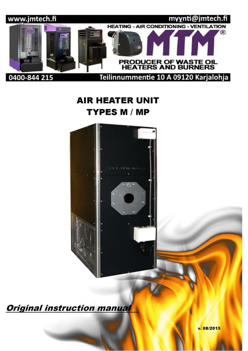
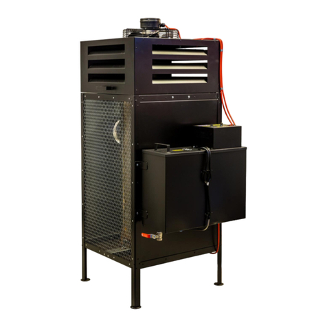
MTM 52 Operation instructions

UNIVERSAL OIL HEATER
TYPE MTM 52 kW
ORIGINAL MANUAL
v. 08/2015

Warsaw, on ............... 20.......... (full name and signature of the person authorised to make the declaration)
EC DECLARATION OF CONFORMITY
MTM DARIUSZ SEFERYŃSKI
HEATING, VENTILATION, AIR CONDITIONING
04-239 WARSAW, ul. MŁODNICKA 52 C
I hereby declare that the oil air heater intended for heating industrial rooms
without central heating systems:
model MTM 52, serial no............................. manufactured in the year 20…….
Rated power of 30-52 kW
Due to its design and structure, meets the basic safety and health requirements set forth in
the Directive 2006/42/EC on machinery and has been manufactured according to the directives as follows:
•Directive 2006/42/EC - on machinery (MD)
•Directive 2006/95/EC - on electrical equipment designed for use within certain voltage limits (LVD)
•Directive 2004/108/EC - on electromagnetic compatibility (EMCD)
•Directive 89/106/EEC - on construction products (CPD)
and the following norms:
•EN 1:1998+A1:2007 Fuel oil stoves with vaporising burners and chimney
connection
•EN 303-5:1999 Heating boilers - Part 5: Solid fuel heating boilers with manual and automatic fuel charge
with rated power of max. 300 KW - Definitions, requirements, testing and marking and labelling.
•EN 953:1997+A1:2009 Safety of machinery - Guards - General requirements for the design and
construction of fixed and movable guards
•EN 60204-1:2006+A1:2009+AC:2010 Safety of machinery - Electrical equipment of machines - Part 1:
General requirements
•EN ISO 12100:2010 Safety of machinery - General principles for design - Risk assessment and
risk reduction
•EN ISO 13732-1:2008 Ergonomics of the thermal environment - Methods for the assessment of human
responses to contact with
surfaces - Part 1: Hot surfaces
•EN ISO 13857:2008 Safety of machinery - Safety distances to prevent hazard zones being reached by
upper and lower limbs
•EN ISO 14159:2008 Safety of machinery - Hygiene requirements for the design of machinery
•EN 60335-1:2002+A14:2010 Household and similar electrical appliances - Safety - Part 1: General
requirements
•EN 55014-1:2006+A1:2009 Electromagnetic compatibility - Requirements for household appliances,
electric tools and similar apparatus - Part 1: Emission
•EN 55014-2:1997+A2:2008 Electromagnetic compatibility (EMC) - Requirements for household
appliances, electric tools and similar apparatus - Immunity - Product family standard
•EN 61000-6-1:2007 Electronic compatibility (EMC) - Part 6-1: Generic standards - Immunity for residential,
commercial and light-industrial environments
•EN 61000-6-3:2007 Electronic compatibility (EMC) - Part 6-3: Generic standards - Emission standard
for residential, commercial and light-industrial environments
The authorisation to compile the machine technical documentation has been given to the representative of the producer:
MTM DARIUSZ SEFERYŃSKI
HEATING, VENTILATION, AIR CONDITIONING
04-239 WARSAW, ul. MŁODNICKA 52 C
Contact person: Dariusz Seferyński
This declaration pertains only to the machine in condition in which it was launched on the market and does not cover componen
t
parts added by the end user or later actions performed by them. This declaration expires
if any changes are made to the device that have not been consulted with us.

1. Heater intended application and technical data
The universal oil heater type MTM 52 is designed to heat up industrial
rooms not covered with central heating systems (workshops, car repair shops,
industrial shops, warehouses, storage buildings, basements, garages, etc.).
The stove can operate using most waste oils of mineral and plant origin,
e.g. engine, gear, hydraulic, fuel oil, with maximal density in temperature of 15°C
equal to 860 kg/m3 and with ignition temperature exceeding 56°C.
DO NOT USE TRANSFORMER OIL AS THEY CAN CONTAIN SUBSTANCES
AFFECTING STOVE OPERATION AND USER HEALTH
TECHNICAL DATA
* Calorific effect specified for fuel with the following parameters:
•calorific value = 42.6 MJ/kg.
•density at temp. max. 15°C = 860 kg/cm3.
In case of higher parameters, the calorific effect can be
increased even up to 55 kW.
2. Storage environmental conditions
The universal oil heater type MTM 52 must be stored in the following conditions:
•temperature from -20°C to 85°C
•relative humidity < 85%
•pressure < 1200 hPa
•no dusting
•environment free from chemical contamination.
3. Use environmental conditions
The universal oil heater type MTM 52 must be used in the following conditions:
•temperature
•relative humidity
•pressure
•IP protection level against environmental impact
•good ventilation of the heated room.
•device noise -
4. Safety aspects
•It is inadmissible to use fuels other than specified in point 1. of the Original Manual.
In particular, it is forbidden to use such fuels as solvents or petrol!
•All activities regarding operation of the device must be performed in protective
gloves and by a person trained for operation.
•It is prohibited to put hands in the protective grids of the furnace or areas of the operating
fan.
•It is necessary to ensure efficient ventilation of the heated room in order to avoid carbon
monoxide poisoning.
from 0°C to 30°C
<85%
<1200
hPa
IP21
not exceeding 70Db
Maximal thermal capacity* kW 52
Minimal thermal capacity* kW 30
Maximal fuel consumption l/h 5.2
Minimal fuel consumption l/h 3
Heated air flow m3/h 5500
Power supply V/Hz 230/50
Maximal power consumption W300
Exhaust fumes outlet diameter mm 150
Device width cm 60
Device height cm 130
Device length cm 120
Device weight kg 120
TEMPLATE OF THE RATING PLATE
PLACED ON THE REAR ENCLOSURE OF THE DEVICE

•While cleaning the device or performing other maintenance activity, the device must be
disconnected from the power network by removing the electrical plug from the power socket.
•While connecting the device to a power network, it must be made sure that the wiring is
operational and that it has differential current protection and earthing.
The MTM 52 universal oil heater is powered by the alternating current network of 230V, 50Hz.
It is equipped with two bimetallic sensors, ensuring safe and economic operation
of the device. The bimetallic sensor located on the heat exchanger reacts with contact shorting when
the temperature exceeds 40°C and with contact opening when the temperature drops below 35°C.
In emergency situations (overheating, oil overflow) the processor checks the bimetallic sensor signal
and maintains the fan operation until the furnace has cooled down to the temperature
below 35°C.
The other bimetallic sensor is located on the heat exchanger as well and its threshold temperature
equals 90°C. Its contact opening resulting from exceeding the threshold temperature causes the stove
to immediately enter the Overheating phase (see point 8. in this Manual). The heater is also equipped
with a weight sensor located under the combustion chamber (i.e. the so-called overflow cut-out).
When the tank of the above cut-out has filled up, the stove automatically switches to the phase
Overflow (see point 8. in this Manual).
5. Controller structure
The connection of the stove controlling panel to other system components (sensors, pump, fan)
is factory-made. During normal use, due to safety, under no circumstances should there be any
interference in the covered part of the stove controller or duct integrity. Any action by an unauthorised
person may result in electrocution (230V AC, 50Hz) and burning.
Fig. 1. The connection of the universal oil heater type MTM 52.

6. Device installation
•read the local Healty and Safety and fire protection regulations,
•place the stove on a flat, concrete floor, in the spot allowing free space around
the device, according to Fig. 2.,
•level the device - in order to check whether the heater is well levelled, place the furnace bowl
in the lower part of the combustion chamber and pour a small amount of diesel oil into it - the oil
should spill out exactly in the middle of the bowl,
•install the draught regulator on the pipe exiting the combustion chamber to ensure stable draught
inside the chamber during heater operation,
•to provide optimal draught, install an at least 5-metre-long smooth, vertical stack pipe
resistant to high temperature (not aluminium),
•check the leaktightness of all stack connections, tighten them with insulating tape
if necessary,
•make sure that the combustion bowl is located in the combustion chamber centrally,
•place the deflector inside the combustion chamber according to Fig. 3.,
•check the network voltage (230V/50Hz) and connect the stove to the power supply. Neither the fan
nor the pump should start because the stove is not switched on yet and no heat has been
produced.
Fig. 2. Minimal safety space around the device.
Fig. 3. Combustion chamber structure
[Flue], [Chamber cover], [Chamber], [Deflector],
[
Pipe
exchanger], [Furnace], [Furnance Bowl]

7. Stack duct installation
The stack outlet of the MTM 52 stove must be capped with the draught regulator (
which is a part of
the standard stove equipment) in the vertical position so that the exhaust fumes outlet is directed
upwards. The stack must be installed into the exhaust fumes outlet of the draught regulator.
To ensure proper combustion, the stack system must be installed properly.
After the installation the following indications have to be followed:
•pipe diameter: 150 mm,
•use the drop separator so that the condensate can leave the stack duct without damaging
the pipe exchanger.
•check the leaktightness of the stack component connections,
•minimal stack height: 5 metres,
•the stack section outside the building should be insulated (a double wall),
•wind should freely fan the stack outlet from all directions (the end of the stack pipe
should be above the rooftop level),
•if possible, all stack sections should be vertical - horizontal sections should be avoided as well as
stack pipe bends. If they are necessary (e.g. two bends if the pipe runs
through a wall or a window), the maximal bend angle equals 45° and the minimal stack height should
be increased to 6 meters,
•the already existing ventilation ducts must not be used to build the stack system!
CAUTION!!!
IF AN ADDITIONAL HEAT EXCHANGER IS INSTALLED ON THE STACK SYSTEM (e.g. EXHAUST
FUMES ECONOMISER), IT IS ADVISABLE TO CLEAN THE EXCHANGER AT LEAST ONCE A MONTH
(depending on the fuel quality) AS ITS INNER WALLS ARE BEING COVERED WITH DUST, WHICH
RESULTS IN A REDUCED CALORIFIC EFFECT OF THE EXCHANGER. A DECREASED DIAMETER OF
EXHAUST FUMES FLOW WILL CAUSE AN EARLY SWITCH OF THE STOVE INTO THE “OVERFLOW”
PHASE AS A RESULT OF BAD COMBUSTION. Places where the stack runs through the ceiling,
walls or the roof must be insulated so as to avoid fire hazard. It is advisable to use a two-layer
insulated stack pipe wherever there is a possibility of touch contact and outside the building, to
ensure constant proper draught and prevent condensation. Do not place any materials near the
stove, even those which are non-inflammable. Ensure constant air supply, necessary for proper
combustion process.
Fig. 4. Stack system
[min. 0.5 m]
[T-connection ⌀150
with drop separator]
[acid-proof stack
pipe ⌀150]
[draught regulator
⌀130/
⌀150]

8. Device operation description
Control panel
The controller of universal oil heater type MTM 52 is equipped with an adjusting knob and two
buttons, which enable the user to control the heater operation, and two diodes indicating the operation
phase of the device, connected to a sound signal in the case of a device failure.
Fig. 4. The front panel of the control module of the universal oil heater.
[STANDBY]
[OPERATION]
[OVERHEATING]
[OVERFLOW]
[PUMP]
[MTM 52 kW STOVE]
The device operates in the following phases:
Stop device ready to operate
Firing up initial phase of device operation
Operation proper phase of device operation
Damping device shutdown process
Overheating emergency shutdown
Overflow emergency shutdown
Heat generation occurs through the combustion of gas produced by the oil heated to high
temperature. At the moment of connecting it to the power network, the device is
in the standby phase (Stop) - no heat is generated, the fan and the pump do not
operate. The diode STANDBY lights on the controller in this time. Pressing the button Start causes the
diode OPERATION to light up and the stove to go into the firing up phase. During this phase, the
diode
OPERATION is blinking. When the furnace has heated up to ca. 40°C, contact shorting of the
control thermostat located next to the combustion chamber occurs and the oil feeding pump and
the downcast ventilator start to operate. On the controller, the diode PUMP lights up, which will blink
for 30 minutes, and the diode OPERATION stops blinking and starts to light
constantly. Due to decreased oil demand by a not heated furnace, after the start-up of the
pump and the fan, the device will operate on minimal power for 30 minutes.
During this time, the pump feeds the furnace with ca. 3 l/h of oil.
After 30 minutes of constant operation, the diode PUMP will stop blinking. The device power may
now be regulated with the knob on the control panel. During maximum power operation,
the furnace is fed with ca. 4.5 l/h of oil.

Automatic stove shutdown may occur in the following cases:
•combustion chamber overheating
•overflow
The overflow signal is generated by the bimetallic sensor located on the heat
exchanger. The contact opening signals that the threshold temperature value has been exceeded. The
control system switches the pump off, overheating is signalled by blinking red diode OVERHEATING
on the control panel. Additionally, a sound signal is made. The heater fan operates until the furnace
emperature falls below 35°C. When this happens, the stove comes back to the Stop phase.
After the device has moved to the Stop phase (and even after disconnecting and reconnecting the
power supply) the overheating signal does not go out. This enables the user to determine the cause for
the stove shutdown. In order to switch the overheating signal off and bring the device to normal
operation, wait until the stove has cooled down (i.e. the fan has switched off) and press the button on
the casing of the bimetallic sensor. Then, press the Stop button, which will cause the heating diode
and the sound signal to turn off. The stove may now be switched on again.
The overflow signal is generated by the micro-switch located under the overflow
tank. The contact opening signals that the tank has overflowed. The control system switches
the pump off, overflowing is signalled by blinking red diode OVERFLOW on the control panel.
Additionally, a sound signal is made. The heater fan operates until the furnace temperature falls below
35°C. When this happens, the stove comes back to the Stop phase.
Then, remove the tank guard located on the side enclosure of the device, empty the overflow tank
and press the Stop button, which will cause the heating diode and the sound
signal to turn off. The stove may now be switched on again.
Fig. 6. The distribution of the heater safety components:
1. Control thermostat and STB thermostat
2. Overflow cut-out (micro-switch)

MARKINGS ON THE MTM17-33 HEATER
[CAUTION! HIGH TEMPERATURE!]
[DO NOT TOUCH THE FUEL OUTLET
AND THE STACK! RISK OF BURN!]
THERMOSTAT
STB
FUEL
INLET
9. The heater operation
CAUTION!!!
OIL MUST NOT BE POURED INTO THE FUEL TANK DURING DEVICE OPERATION. OIL MUST
NOT BE POURED INTO THE FURNACE AND IT MUST NOT BE FIRED UP IF THE FURNACE
CHAMBER OR BOWL ARE STILL HOT!!! ALWAYS WAIT UNTIL THE BURNER PLATE
HAS COOLED DOWN ENTIRELY.
FAILING TO FOLLOW THE ABOVE INSTRUCTIONS MAY RESULT IN AN UNCONTROLLED
IGNITION OF OIL FUMES AND SCALDING. IT MAY ALSO CAUSE DESTRUCTION OF
CAST IRON ELEMENTS!!!
Switching the device on
While starting the device, the user may stand on the left or right side or in front of the device. Caution
is advised so that the flap of the device does not slam the hands. Therefore, the user must not perform
any actions intended to start the device when they are behind it.
After start-up, the heater enters proper phases of operation depending on the settings provided by the
user and information fed by the sensors in the control system.
•Remove water from the fuel tank and fill it with oil (e.g. used oil) if necessary.
•Check whether the feeding pipe (burner) of the device is maximally pushed to the device housing (if
not, push it).
•Insert the power plug in the power socket (230V / 50Hz) - the diode STANDBY lights up.
•Draw the top part of the heater housing aside and remove the combustion chamber cover.
Then, take the deflector out (if necessary, thoroughly clean the combustion bowl, the base which
it is placed on and the entire combustion chamber).
•Check whether the furnace bowl is cool and clean and pour ca. 250 ml of fuel or diesel oil.
•Install the deflector.
•Fire the oil up using paper crumbled into a ball - set it on fire and throw onto the furnace bowl.
•Replace the combustion chamber cover, fastening it with locks, and close the top housing part
of the heater.
•Press the Start button on the control panel (the diode OPERATION will start to blink).
•After about 10-15 minutes, depending on the room temperature, the fuel pump and the fan
will activate and the stove will start to operate on the minimal power, regardless of the
position of the power regulating knob (30 kW; combustion at ca. 3 l/h). After 30 minutes, it will be
possible to regulate the device power with the regulating knob. If the knob, at start-
up,
was in another position than minimum, the device will automatically start
operating with the power set by the regulating knob position after 30 minutes.

Each pressing of the Stop button and restarting with the Start button during
its operation time will cause the stove to reenter the firing up phase.
Switching the device off
The heater is switched off by pressing the Stop button on the control panel,
which switches off the fuel pump. The heater fan operates until the furnace temperature drops
below 35°C (Damping). When this happens, the stove comes back to the Stop phase.
The device must not be disconnected from the power supply during the fan operation - wait
until the stove has cooled down. The stove switches off automatically. Please note that after
the device has switched off, the cast iron bowl maintains a higher temperature for some time
(depending on the ambient temperature) and stove cannot be fired up again until it cools down!
Maintenance
The heater requires little maintenance activity. Following the producer’s indications
in this area will ensure safe and failure-free operation of the device:
•clean the furnace bowl and other combustion chamber elements everyday before firing up.
The maximal device operation time without cleaning the bowl is about 7-12 hours (depending
on the employed oil intended for combustion),
•check the passability of the overflow pipe (the pipe in the lower part of the combustion chamber,
directly over the overflow bowl), clean if necessary.
•clean the combustion chamber base (the element under the furnace bowl) at least once a week,
•check whether the air inlet openings in the lower and upper part of the combustion chamber
are not blocked,
•clean the rubber duct feeding oil onto the furnace bowl at least once a week,
•clean the fuel tank and oil pump filter during the heating season,
•if the stove is going to be off for a longer time, carefully clean the combustion chamber and
the furnace bowl and protect them against corrosion by coating them with a thin layer of oil.
IT IS ADVISED TO CONDUCT SEASONAL INSPECTIONS
IN AN AUTHORISED SERVICE CENTRE
CAUTION!!!
DUE TO EXHAUST DUST ACCUMULATING
IN THE PIPE EXCHANGER, IT IS ADVISABLE TO CLEAN IT
AT LEAST ONCE A YEAR BEFORE THE HEATING SEASON!

10. What to do if the device fails
In the case of the device failure, the following list may help to determine its location. Generally, its
removal is fairly easy. The most frequently occurring problems are listed below. The numbers indicate
possible causes for failure. The order of the numbers shows the probability of a given failure
occurrence.
NOTE:
Prior to performing any maintenance or repair activity of the device, disconnect its power
plug from the power socket.
FAULT CAUSE
The pump does not start and the operation indicating lamp does not light up 6-3-7
The fire goes out and the pump still does not operate 2-5-9-10-12
The combustion chamber rumbles. 10-11-12
Soot appears in the combustion chamber and the stack. 8-9-10-11-12
Unburnt oil remains on the furnace bowl. 8-9-11-12
No. CAUSE SOLUTION
1No power supply. • Check if the plug is in the socket
and check the fuses.
2Water or deposit in the tank. • Clean the tank and filter.
3The pump motor does not turn on. • Check STB and overflow protection.
4The motor and pump do not operate.
•The fuel is too thick or too cold. Dilute with
diesel oil.
•Check the pump control thermostat and
replace it if needed.
•Check the motor and see if the pump is not
soiled on the inside.
•Check STB and overflow protection.
5
The fuel ducts is obstructed, oil
returns to the tank through the primary
duct.
• Clean the fuel duct and replace it if needed.
6The pump operation control thermostat
has not reached proper temperature.
•Wait until the furnace cools down and restart it.
•Replace the thermostat.
7The overflow protection is full. • Clean it.
8The safety thermostat (STB) does not
operate properly or at all.
•Reset the thermostat by pressing it.
•Replace it.
9Insufficient combustion air
supply.
•Clean the furnace chamber openings.
•Check proper operation of the fan.
10 Improper draught.
•Check if the stack pipe is mounted according to
recommendations entitled: “Stack ducts
installation”.
•Check tightness of the stack system.
•Clean if necessary.
11 The stack draught is too strong or
alternates to much.
• Install the draught stabiliser and adjust it to
min. 2 mm W.C. (19.6 Pa).
12 The stack draught is too weak.
•Check all connections.
•Decrease the number of bends.
•Elongate the stack.
•Insulate the stack pipe outside the building.
•Review all information regarding the stack duct
in the Manual.
Table of contents
Other MTM Heater manuals
Popular Heater manuals by other brands

ARDES
ARDES AR4F06 Instructions for use

Munters
Munters GRY-I 40 WU Operating, installation and service instructions

Well Bubbler
Well Bubbler 10-120 Installation and configuration manual

Desa
Desa 30 owner's manual

cecotec
cecotec Ready Warm 6000 Ceramic instruction manual

Italkero
Italkero Echo XC Instructions of use