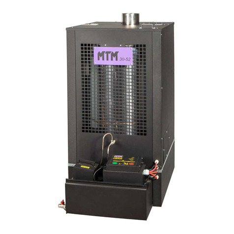
MTM 8-30 Operation instructions

UNIVERSAL OIL HEATER
TYP MTM 8-30 kW
V. 08/2015
ORIGINAL MANUAL

EC DECLARATION OF CONFORMITY
MTM DARIUSZ SEFERYŃSKI
HEATING, VENTILATION, AIR CONDITIONING
04-239 Warsaw, ul. MŁODNICKA 52 C
I hereby declare that the oil air heater intended for heating industrial rooms
without central heating systems:
model MTM 8-30, serial no.......................................... manufactured in the year 20……..
Rated power of 8-30 kW
due to its design and structure, meets the basic safety and health requirements set forth in
the Directive 2006/42/EC on machinery and has been manufactured according to the directives as follows:
•Directive 2006/42/EC - on machinery (MD)
•Directive 2006/95/EC - on electrical equipment designed for use within certain voltage limits (LVD)
•Directive 2004/108/EC - on electromagnetic compatibility (EMCD)
•Directive 89/106/EEC - on construction products (CPD)
and the following norms:
•EN 1:1998+A1:2007 Fuel oil stoves with vaporising burners and chimney connection
•EN 303-5:1999 Heating boilers - Part 5: Solid fuel heating boilers with manual and automatic fuel charge
with rated power of max. 300 KW - Definitions, requirements, testing and marking and labelling.
•EN 953:1997+A1:2009 Safety of machinery - Guards - General requirements for the design and
construction of fixed and movable guards
•EN 60204-1:2006+A1:2009+AC:2010 Safety of machinery - Electrical equipment of machines - Part 1:
General requirements
•EN ISO 12100:2010 Safety of machinery - General principles for design - Risk assessment and risk reduction
•EN ISO 13732-1:2008 Ergonomics of the thermal environment - Methods for the assessment of human
responses to contact with surfaces - Part 1: Hot surfaces
•EN ISO 13857:2008 Safety of machinery - Safety distances to prevent hazard zones being reached by upper
and lower limbs
•EN ISO 14159:2008 Safety of machinery - Hygiene requirements for the design of machinery
•EN 60335-1:2002+A14:2010 Household and similar electrical appliances - Safety - Part 1: General
requirements
•EN 55014-1:2006+A1:2009 Electromagnetic compatibility - Requirements for household appliances,
electric tools and similar apparatus - Part 1: Emission
•EN 55014-2:1997+A2:2008 Electromagnetic compatibility (EMC) - Requirements for household
appliances, electric tools and similar apparatus - Immunity - Product family standard
•EN 61000-6-1:2007 Electronic compatibility (EMC) - Part 6-1: Generic standards - Immunity for residential,
commercial and light-industrial environments
•EN 61000-6-3:2007 Electronic compatibility (EMC) - Part 6-3: Generic standards - Emission standard for
residential, commercial and light-industrial environments
The authorisation to compile the machine technical documentation has been given to the representative of the producer:
MTM DARIUSZ SEFERYŃSKI
HEATING, VENTILATION, AIR CONDITIONING
04-239 Warsaw, ul. MŁODNICKA 52 C
Contact person: Dariusz Seferyński
This declaration pertains only to the machine in condition in which it was launched on the market and does not cover
component parts added by the end user or later actions performed by them. This declaration expires
if any changes are made to the device that have not been consulted with us.
Warsaw, on ……………………..
20.....
(full name and signature of the person authorised to make the declaration)

1. Intended application
The universal oil heater type MTM 8-30 is designed to heat up industrial
rooms not covered with central heating systems (workshops, car repair shops,
industrial shops, warehouses, storage buildings, basements, garages, etc.). The furnace can operate using most
oils, e.g. engine, transmission, hydraulic, diesel oil, HBO I, II and III type oil, with viscosity
not exceeding SAE 80.
DO NOT USE TRANSFORMER OIL
AS IT MIGHT CONTAIN SUBSTANCES HARMFUL FOR STOVE OPERATION
TECHNICAL DATA
Maximal thermal capacity*
KW
30
Minimal thermal capacity *
KW
8
Maximal fuel consumption
l/h
3.0
Minimal fuel consumption
l/h
0.8
Heated air flow
m3/h
1460
Power supply
V/Hz
230/50
Maximal power consumption
W
100
Exhaust fumes outlet diameter
mm
130
Device width
cm
92
Device height
cm
135
Device length
cm
54
Device weight
kg
50
*Calorific effect specified for fuel with the following
parameters:
•calorific value = 42.6 MJ/kg.
•density at temp. max. 15°C = 860 kg/cm3.
In case of higher parameters, the calorific effect can be increased
even up to 33 kW.
TEMPLATE OF THE RATING PLATE PLACED
ON THE REAR ENCLOSURE OF THE DEVICE
2. Storage environmental conditions
The universal oil heater type MTM 8-30 must be stored in the following conditions:
temperature -20..85°C
relative humidity 5..85%
pressure 800..1200 hPa
no dusting
environment free from chemical contamination.
3. Use environmental conditions
The universal oil heater type MTM 8-30 must be used in the following conditions:
temperature 0..30°C
relative humidity 5..85%
pressure 800..1200 hPa
IP protection level against environmental impact IP65
good ventilation of the heated room.
4. Controller characteristics
•three-stage power adjustment for the stove 8-19-30 kW,
•preserving settings after blackout.
5. Safety aspects
The MTM 8-30 universal oil heater is powered by the alternating current network of 230V/50Hz. It is
equipped with three sensors, ensuring safe and economic operation of the device.
1. The bimetallic sensor, placed in the furnace chamber, reacts with short circuit of the contacts in the
thermostat when the temperature exceeds 40°C and with contact opening when the temperature drops below
35°C.
2. The bimetallic sensor is located near the downcast ventilator, with threshold temperature
of 100°C, opens the contacts when the said temperature is exceeded and causes switching of the stove in to the

emergency mode, cutting off inflow of fuel, thus securing the fan against overheating or melting
of its elements.
3. Microswitch - weight sensor located under the combustion chamber. Filling the pan causes
immediate switching into the emergency mode, cutting off the fuel inflow, securing against
leakage of the excess non-evaporated fuel outside the combustion chamber, eliminating the possibility of its
ignition
outside the device.
The connection of the stove controlling panel to other system components (sensors, pump, fan)
is factory-made. During normal use, due to operation safety, under no circumstances should there be any
interference in the covered and sealed part of the stove controller or duct integrity. Any action by an
unauthorised person may result in electrocution (230V AC, 50Hz) and burning.
6. Structure of STOVE MTM 8-30
Fig. 1. MTM 8-30 heater structure
Fig. 2. MTM 8-30 heater block diagram.
BIMETALLIC
OVERHEAT
SENSOR (STB)
RESET
CONTROLLER
FUEL
TANK
FUEL
FEEDING
PUMP
BURNER
CONTROL
THERMOSTAT
FAN
HOUSING
UPPER
HOUSING
OF THE
COMBUSTION
CHAMBER
EXHAUST FUMES OUTLET
COMBUSTION
CHAMBER
TROLLEY
OVERFLOW
SENSOR
CONTROL
THERMOSTAT
FAN
CONTROLLER
FUEL
PUMP
MOTOR
OVERFLOW
PAN
TRANSFOR
MER
FUSE

7. Device installation
-familiarise with the local regulations,
-set the stove on a flat and hard ground,
-level the device,
-to provide optimal draught, install an at least 5-metre-long smooth, vertical stack pipe
resistant to high temperature (not aluminium), preferably
made of stainless steel,
-check the tightness of all connections, tighten them with insulating tape,
-make sure the elements inside the combustion chamber are properly mounted and the burner
is pushed to the end,
-check the network voltage (220-240V/50Hz) connecting the stove to power supply and changing the
position of switch 0/1,
-check if the switch lights up red when in position 1.
7a. Stack ducts installation
To ensure proper combustion, the stack system must be installed properly.
After the installation the following indications have to be followed:
-diameter of the exhaust fumes outlet from the device is 130 mm,
-recommended diameter of the stack pipe is 130 - 150 mm,
-minimal stack height with diameter of 150 mm is 5 metres,
-check the tightness of the stack component connections,
-wind should freely fan the stack outlet from all directions (the end of the stack pipe
should be above the rooftop level),
-wind should freely fan the stack outlet from all directions - the end of the stack pipe
should be above the rooftop level,
-if possible, all stack sections should be vertical - horizontal sections should be
avoided as well as stack pipe bends. If they are necessary (e.g. two bends if the pipe runs
through a wall or a window), the maximal bend angle cannot exceed 45°
and the minimal stack height should be increased to 6 meters.
Fig. 3. Structure and components of the combustion chamber
CHAMBER COVER
CYLINDER
DEFLECTOR
RING
CHAMBER JACKET
OVERFLOW TUBE
FURNACE PAN
CHAMBER BASE

CAUTION
When installing the exhaust discharge system it is recommended to avoid horizontal sections of the stack pipe.
In order to ensure free flow of gases, the angle of potential pipe bend should not exceed/be lower than 45°.
The stack outlet must be above the roof top, preferably by ca. 1 m.
The places where the stack penetrates the ceiling, walls or roof must be insulated in order to avoid fire hazard.
It is recommended to use a double-layered insulated stack pipe wherever contact is possible as well as outside
the building in order to ensure continuous draught and prevent condensation. Do not place any materials near
the stove, even non-flammable ones. Provide continuous air access, necessary for the proper combustion
process.
Fig. 4. Stack installation

8. Description of device operation
8a. Control panel
The MTM 8-30 type universal oil stove controller is equipped with the power setting knob, network
switch and fuse socket.
Fig. 5. Vide of the front control module panel.
8b. The operation of the device is characterised by the following statuses:
• Stop
device ready for start-up
preliminary device operation stage
proper operation device operation
device switch-off
emergency switch-off
• Firing up
• Operation
• Damping
• Overheating
• Tank overflow
Heat generation occurs through the combustion of gas produced by the oil heated to high temperature. At the
moment of connecting it to the power network, the device is in the standby phase (Stop) - no heat is generated, the fan and
the pump do not operate.
Pressing the button marked as NETWORK in position 1 causes switching into readiness for firing up (see firing up in
point 9a). When the furnace has heated up to ca. 40°C, the oil feeding pump and downcast ventilator are switched on, the
red lamp of switch 0/1 is turned on.
Due to decreased oil demand by a non-heated furnace, after the start-up of the device it should operate with 19
kW power for at least 15 minutes. After ca. 15 minutes of operation, when the furnace pan is sufficiently heated up and is
able to evaporate a greater amount of oil, the power of the device can be switched to 30 kW or lower - 8 kW. During
maximum power operation, the amount of oil fed to the furnace is ca. 3 litres.
The heater is switched off by pressing the NETWORK button into position “0” on the control panel. This causes
switching off. The downcast ventilator operates until the furnace temperature falls below ca. 35°C (Damping). Having
reached temperature below 35°C, the stove comes back to the Stop phase.
The stove can be automatically switched off in the following cases:
-overheating of the combustion chamber,
-overflow.
The overflow status is generated by the bimetallic sensor located near the fan.
The contact opening signals that the threshold temperature value has been exceeded. The control system switches off the
pump feeding fuel, and the fan operates until the furnace temperature falls below 35°C. Having reached
temperature below 35°C, the stove comes back to the Stop phase.

In order to return to normal operation, wait until the stove has cooled down
(i.e. the fan has switched off and the chamber is cooled down) and press the button on the casing of the
bimetallic sensor (reset).
Clean the chamber pan, taking into account that the pan and deflector can still be hot due to the fact that
cast iron keeps temperature for a long time. Then the stove can be switched on according to point 9a.
The overflow signal is generated by the mechanical sensor located under the overflow tank.
The contact opening signals that the tank has overflowed and switches off the fuel feeding pump and the fan
keeps operating until the furnace temperature falls below 35°C. When this happens, the stove comes back
to the Stop phase.
In order to return to normal operation, wait until the stove has cooled down (i.e. the fan
has switched off and the chamber is cooled down). Drain the overflow tank, clean the furnace pan and the
combustion
chamber, taking into account that the pan and deflector can still be hot due to the fact that cast iron keeps
temperature for a long time. Then the stove can be switched on according to point 9a.
9. Heater operation
CAUTION!!!
DO NOT RE-FILL OIL IN THE FURNACE AND FIRE UP WHEN THE CHAMBER OR
FURNACE PAN ARE STILL HOT!!!
ALWAYS WAIT UNTIL THE FURNACE PLATE HAS FULLY COOLED DOWN. FAILURE TO
OBSERVE THE ABOVE MAY RESULT IN
UNCONTROLLED IGNITION OF OIL VAPOURS AND BURNS!!!
9a. Starting the device.
-if needed, remove water from the fuel tank and fill it with oil (e.g. used oil),
-check whether the overflow protection mechanism works properly by
pushing the bowl lever down and letting it come back to its original position, which
will be confirmed by the characteristic “click” sound,
-check whether the device burner is maximally pushed to the housing of the device (if not,
push until resistance),
-insert the power plug in the power socket (230V / 50Hz),
-draw the top part of the heater housing aside and remove the combustion chamber cover.
Then, take the cylinder and deflector out (if necessary, thoroughly clean the combustion bowl, the base
which it is placed on and the entire combustion chamber along with the sleeve and deflector),
-check whether the furnace bowl is cool and clean and pour ca. 250 ml of fuel or diesel
oil,
-mount the ring and cylinder,
-fire the oil up using paper crumbled into a ball - set it on fire and throw onto the furnace bowl,
-replace the combustion chamber cover and close the top housing part of the heater,
-press the button marked as NETWORK into position 1 and turn the power setting knob into 19 kW
or 19 kW, depending on the required heat amount,
-after about 10-15 minutes, depending on the room temperature, the fuel pump and the fan
are switched on and the red lamp of the 0/1 button is on. The stove has to operate with this power
for at least 15 minutes. After ca. 15 minutes of operation, when the furnace pan is sufficiently heated up
and is able to evaporate a greater amount of oil, the power of the device can be switched to 30 kW or
decreased to 8 kW.

9b. Switching the device off
In order to switch the device off and complete the heating process, turn the power setting knob
on the control panel into the fan position and switch the button marked as MAINS to 0, causing the lamp
to switch off. The pumps will stop feeding fuel to the combustion pan and the ventilator will operation until the
stove has cooled down. The damping process depends on the room temperature and degree of heating
of the combustion chamber and it can vary from 20 to 40 minutes.
DO NOT disconnect the device from power supply when the fan is operating! Wait until the stove has cooled
down. The stove is switched off automatically. Remember that after the stove is switched off, the cast iron pan
keeps higher temperature for some time (depending on the ambient temperature) and the stove cannot be
fired up again until the pan has fully cooled down! DO NOT throw the hot* pan on the snow, do not pour cold
water on it in order to cool it down - a hot pan, due to the great temperature difference, can break and will be
unfit for use!!!
9c. Maintenance
The heater does not require many maintenance procedures. Observance of the manufacturer’s
recommendations in this scope will ensure failure-free and safe operation of the device:
-clean the furnace pan every day as well as other elements of the combustion chamber (cylinder,
deflector and cover),
-check patency of the overflow tube (tube in the bottom part of the combustion chamber, directly
above the overflow pan), clean if needed,
-at least once a week clean the combustion chamber base (element under the furnace pan),
-check if the openings of the air inlet in the upper and bottom part of the combustion chamber are not
covered,
-at least once a week clean the fuel feeding tube (burner), maximal operating time
without furnace pan cleaning is ca. 7-15 hours (depending on the oil used for combustion),
-clean the fuel tank and oil pump filter during the heating season,
-if the furnace is switched off for a longer period of time, the combustion chamber and day
tank must be thoroughly cleaned and then secured against corrosion with a thin layer of oil.
SEASONAL INSPECTIONS BY AUTHORISED SERVICE CENTRE
RECOMMENDED

10. Failure repair
In case of device failure, the list provided below might help in locating in. Removal is usually
simply. Potential problems are specified below. The numbers indicate the possible causes. The order of numbers
shows the probability of failure.
CAUTION:
Unplug the device prior to commencement of any activities.
FAILURE
The pump fails to launch
The flame goes out and the pump keeps working
Noise from the combustion chamber.
Soot in the combustion chamber and stack.
Unburnt oil left on the combustion plate.
CAUSE
6-3-7
2-5-9-10-12
10-11-12
8-9-10-11-12
8-9-11-1 or excess of diesel
oil during start-up.
No.
CAUSE
SOLUTION
1
No power supply.
•Check if the plug is in the socket and check
fuses
2
Water or deposit in the tank.
• Clean the tank and filter.
3
The pump motor does not turn on.
• Check STB and overflow protection.
4
The motor and pump do not operate.
•The fuel is too thick or too cold.
Dilute with diesel oil.
•Check the pump control thermostat
and replace it if needed.
•Check the motor and see if the pump
is not soiled on the inside.
•Check STB and overflow protection.
5
The fuel ducts is obstructed, oil
returns to the tank through the primary duct
• Clean the fuel duct and replace it.
6
The pump operation control thermostat has
not reached proper temperature.
•Wait until the furnace cools down and restart it
•Replace the thermostat.
7
The overflow protection is full
• Clean it.
8
The safety thermostat (STB) does
not operate properly or at all
•Reset the thermostat
•Replace it.
9
Insufficient combustion air inflow
•Clean the furnace chamber openings.
•Check proper operation of the fan.
10
Improper draught.
•Check if the stack pipe is mounted according to
recommendations in point 7a
•Check tightness of the stack system.
•Clean if necessary.
11
The stack draught is too strong or
alternates too much.
• Install the draught stabiliser
and adjust it to min. 2 mm W.C. (19.6 Pa).
12
The stack draught is too weak.
•Check all connections.
•Decrease the number of bends.
•Elongate the stack.
•Insulate the stack pipe outside the building
•Review all information regarding
the stack duct in the Manual.

Servicing part diagram for MTM 8-30

830.1 STOVE STRUCTURE WITH FAN HOUSING
830.2 - REAR COMBUSTION CHAMBER COVER
830.3 - AXIAL FAN fi250mm
830.4 - FUEL TANK
830.5 - FUEL TANK COVER
830.6 - CONTROLLER HOUSING
830.7 - CONTROLLER LABEL
830.8 - OVERFLOW PROTECTION
830.9 - CAPILLARY HANDLE
830.10 - ELECTRONIC PLATE OF THE CONTROLLER
830.11 - FUEL PUMP BRACKET
830.12 - DRIVE SHAFT OF THE FUEL PUMP
830.13 - FEEDING TUBE FOR THE COMBUSTION CHAMBER
830.14 - MTM 8-30 STOVE SWITCH
830.15 - FUSE SOCKET
830.16 - RUBBER GLAND
830.17 - ELECTRONIC PLATE TRANSFORMER OF THE MTM 8-30 STOVE
830.18 - CAPILLARY CONTROL THERMOSTAT
830.19 - FUEL DUCT T-PIPE
830.20 - COMBUSTION CHAMBER
830.21 FUEL PUMP FILTER
830.22 - CLEANING BLADE FOR THE COMBUSTION CHAMBER
830.23 - STB THERMOSTAT
830.24 - OVERFLOW MICROSWITCH
830.25 - CAST IRON FURNACE PAN
830.26 - CAST IRON COMBUSTION CHAMBER DEFLECTOR
830.27 - COMBUSTION CHAMBER CYLINDER
830.28 - COMBUSTION CHAMBER RING
830.29 - FUEL PUMP
830.30 - RUBBER FEEDING FUEL DUCT 12 cm LONG
830.31 - RUBBER OVERFLOW FUEL DUCT 30 cm LONG
830.33 - FUEL PUMP MOTOR
830.34 - SUPPLY CABLE 230 WITH A PLUG
830.35 - ELECTRIC FIRE-RESISTANT WIRE 3X 105 cm LONG STB
830.36 - ELECTRIC FIRE-RESISTANT WIRE 3X 115 cm LONG FAN
830.37 - ELECTRIC FIRE-RESISTANT WIRE 3X 145 cm LONG OVERFLOW PAN
830.38 - LARGE GLAND
830.39 - COMBUSTION CHAMBER COVER
List of servicing parts for MTM 8-30
Table of contents
Other MTM Heater manuals