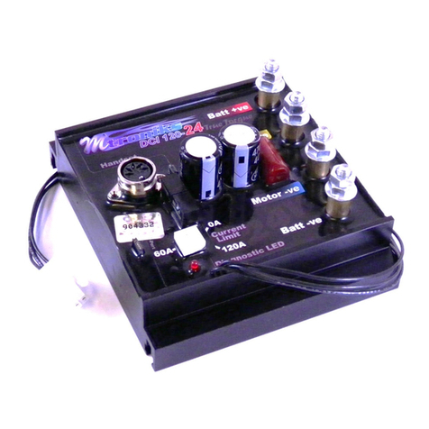
Mtroniks True Torque DCI250-24 T User manual

1
DCI250-24 True Torque TM Manual June 2017 Mtroniks Ltd.
DC MOTOR SPEED CONTROLLER
MODEL: DCI250-24 True Torque TM
Thank you for choosing Mtroniks to control your model.
Overview
For over 20 years Mtroniks have been at the forefront of electronic speed control design and
manufacture for the hobby industry.
Our products are designed and manufactured entirely in house in the UK. The DCI range of
controllers has been developed over the last 4 years. The extensive research and design program
looked at every aspect of the problems associated with the speed control of large scale models.
We hope you will find the DCI range of controllers is refreshingly different in many ways; it’s not
designed down to price. We developed a strong core of electronics which during rigorous testing,
has proven to be ‘well on top of the job’
The use of a large and powerful computer core has allowed us to incorporate features and
protection measures not usually found on these types of controllers. These particular controllers are
aimed at large locomotives of 3 ½ “ gauge and up. This is where we have tested extensively, actually
in real applications.
True Torque TM Motor torque control system
Accurately measuring the current in the motor can be a difficult problem to solve in a model speed
controller. For this reason, DC motor speed controllers normally control and if necessary limit the
battery current.
However, at low motor speeds and high torque this can lead to severe motor overload because the
current in the motor can be much higher than the average battery current.
Our new control system monitors every motor pulse and if necessary, adjusts the pulse to keep the
motor current (Torque) to the maximum value set on the current control pre-set.
The usual problems of brush burning and motor overheating which occur because of magnetic
saturation in overload are prevented.

2
DCI250-24 True Torque TM Manual June 2017 Mtroniks Ltd.
Using your controller
General
Your new controller is simple to use and configure for use in your model, but there are a few
important aspects which you should understand BEFORE you wire it into your model.
1) ALWAYS fit a fuse. Between 125 & 200Amp fuse in line with the positive (+ve) 24V supply
feed from your battery.
2) Make sure that you use DOUBLE 10mm² wires, thin wires may heat up and melt, possibly
causing short circuits or fires. The currents seen in ride on type locomotives can easily
exceed 100Amps.
3) BE VERY SURE NOT to accidentally reverse connect to the battery, even a momentary touch
on the wrong battery terminal can cause fatal damage to your controller. This will blow the
‘tell tale’ and your warranty does not cover damage due to reverse connection.
4) ENSURE that the dead-man device is fitted around the drivers wrist, failure to do so is a
direct compromise on safety.
5) This unit is designed to be used by an adult and not to be left without adult supervision.
Installation notes
Install the controller power module into your model somewhere close to the battery, this helps to
keep the battery wires as short as possible.
The power module gets warm during use, fastening the module to a metal chassis is ideal.
The power module only has 9 connections, 4 for the 24V battery supply, 4 for the motor/motors
connections and one multi-way connector which allows connection to the controller handset.
NOTE: The small pin connectors are for factory use only. These are used for firmware/software
updates. Depending on the model of the controller there may be fibre optic interface connections
for master/slave operation. BE VERY CAREFUL TO NEVER interfere or damage these connections.
Using your model
The throttle control is disabled at switch on unless it is in the neutral band or is returned to neutral
position after switch on.
Always apply power gently and progressively, rapid acceleration wears the motor brushes more
quickly and places much greater stress on the drive train components.
The current control pre-set trimmer on your controller is FRAGILE, we strongly recommend that you
use a jewellers screwdriver to CAREFULLY turn the control up or down.
If you know the manufacturers maximum rated current for your motor then this is the MAXIMUM
current you should set on the control. If not, start low and work up, regularly checking the
temperature of the motor.

3
DCI250-24 True Torque TM Manual June 2017 Mtroniks Ltd.
As a rough guide there will come a point when further upward adjustment does not improve the
power output. This is the maximum current/torque that the motor can handle. Adjust the control
BACK a little and leave it there.
If you are travelling in one direction and switch to the opposite direction using the direction toggle
switch, the controller will apply maximum brakes and stop. It will not apply power in the other
direction until the throttle control is first returned to the neutral position for 2 seconds or longer.
The emergency stop button will, when pressed momentarily, apply maximum brakes and when close
to stopping, the controller will short the motor to apply absolute maximum brakes. The power to the
unit MUST be switched off then back on again to reset an emergency stop.
The ‘dead man’ jack plug is located on the front edge of the controller handset, when removed, full
brakes are applied as in an emergency stop condition.
If your model does not respond to the handset please check the diagnostic light on the speed
controller. It may be flashing in a sequence, see below.
1 Flash = Problem with the dead man switch –check it is secure
2 Flashes = Handset problem –Make sure it is connected correctly and not damaged
3 Flashes = Master/Slave optical coupling problem –check cable is not damaged and fitted ok
Features
oFully regenerating, digital, high frequency operation
oAnti-lock brakes
oPatented motor current/Torque limiter system
oMaster/Slave configuration –Fibre optic link
oIntelligent control bus –Failsafe & ‘Dead man’safety plug
oWaterproof power module
o24v DC operation /240Amps maximum
oOver temperature protection
oUltra smooth power control
oFirmware/Software upgradeable
o6.0mm studs for heavy duty power connections

4
DCI250-24 True Torque TM Manual June 2017 Mtroniks Ltd.
Optional Accessories
Description Part No.
oSupply fuse and holder DC250SF
o2m red/black 10.0mm² cable w/connectors DC250W2M
o1m red/black 10.0mm² cable w/connectors DC250W1M
oSpare/Replacement handset DCI Handset
oHandset cable assembly DCI Cont Cable
oFibre optic cable (3.0m) DCI Fibre Cable(3m)
oFibre optic cable (10.0m DCI Fibre Cable (10m)
oRelay board for auxiliary outputs DC/AC RL424V
APPENDIX1
Master/Slave operation (Controller specific)
The DCI range of controllers come with the factory specified option of being able to link more than
one controller via a fibre optic cable.
This allows 2 or more controllers to be operated together from one single handset. The maximum
length of fibre optic cable which can be used is 20.0m, this denotes the maximum distance you can
have between 2 controllers. Applications include ‘topping and tailing’ train configurations and also
very high power, multi motor, locomotives.
When the second controller is set to slave, it is controlled, via the optical link, by the first ‘master’
controller which is controlled by the handset.
The fibre optic cable is the ideal way to connect the controllers, there is no electrical connection
between the 2 controllers and no wires to damage or short out.
If the optical cable is broken, the slave controller will revert to neutral and freewheel until you can
stop and repair/replace the cable.
Connection details for optically coupled systems
Speed controllers equipped with Master / Slave feature have 2 fibre optic cable connections and
a switch.
The switch is used to select which speed controller is the master and which is the slave. The 2
fibre optical coupler connections are colour coded black and white. The white is the OUTPUT
connector and the BLACK is the input connector.
The output connector emits a red coloured light which contains all the digitally encoded
information for the 2nd controller.
The fibre optic cable should be GENTLY inserted into the white (output) connector on the
MASTER controller ( the one with the handset attached to it) and into the BLACK ( input)
connector on the slave controller.

5
DCI250-24 True Torque TM Manual June 2017 Mtroniks Ltd.
It is very important that the ends of the fibre optic cable are clean and cut flat at the ends
otherwise the transmission of light can be impeded sufficiently to cause problems with the
operation of the slave controller.
The toggle switch is set to slave when it is inboard and master when it is towards the outside
edge of the speed controller.
If there is a communication problem between the speed controllers and the slave controller
loses its signal ( snapped or damaged fibre cable ) then the slave controller will fail safe to
NEUTRAL and flash its LED continuously to indicate a failure in communication. Under these
circumstances it is necessary to disconnect the battery supply from both speed controllers , wait
a minute and try again.
APPENDIX2
Auxiliary switched outputs
The DCI controller has up to 4 auxiliary switched outputs. These connections are controlled by the 4
switches on the handset.
The 4 connections on the controller are ‘switched to ground’ outputs. This means that they are
designed to switch the coil of a relay.
The auxiliary relay board (DC/AC RL424V) allows you to wire the 4 auxiliary connections from the
DCI250 to the inputs on the relay board allowing control of up to 4 auxiliary outputs, such as a horn
or sound module.

6
DCI250-24 True Torque TM Manual June 2017 Mtroniks Ltd.
Suggested wiring diagram
If running two motors, connect one motor to each of the motor terminal pairs. We also advise
doubling up your power wires to the battery by connecting to both pairs of connectors.
General user notes
When installing an extension cable between the speed controller and the locomotive bulkhead it is
very important to make sure that the bulkhead connection is electrically insulated from the
locomotive chassis otherwise electrical noise in the chassis can be coupled into the handset control
signals causing cut outs and failsafes. The best way to do this is to fit the metal socket at the
bulkhead into an insulating mounting (this can be fibreglass or plastic) and then fasten the mounting
to the bulkhead or buffer beam.
While you may be strongly tempted to construct your own extension lead we strongly recommend
the use of our optional accessory as this is a high frequency digital control bus and the signals can
easily be corrupted by a poor connection.
Brakes
The strength of the braking effect of a DC motor is proportional to its speed of rotation. It follows
that a stationary or very slowly rotating motor will provide little or no noticeable braking effect. For
most normal running, this system works well, the faster the model is travelling the stronger the
available maximum brake will be.
The electronic brake on your system is NOT a handbrake. For this reason we always strongly
recommend the inclusion of a mechanical brake system to hold the model on hills and bring it to a
full stop.
Table of contents
Other Mtroniks Controllers manuals