MUEGGE Magnetron Head MH3000S-211CV User manual

Roth & Rau Muegge GmbH – Hochstraße 4-6 – 64385 Reichelsheim
Tel.: +496164 9307 0 – Fax: +496164 9307 93
E-mail: [email protected]
Magnetron Head
Type: MH3000S-211CV
Operating instructions
English version
– Internet: www.muegge.de
MH3000S-211CV00008100102.doc
- 1 -

Roth & Rau Muegge GmbH – Hochstraße 4-6 – 64385 Reichelsheim
Tel.: +496164 9307 0 – Fax: +496164 9307 93
MH3000S-211CV00008100102.doc
- 2 -
1. IDENTIFICATION................................................................................................ 5
1.1 Product brand and type designation.............................................................................................. 5
1.1.1 Rating plate....................................................................................................................................... 5
1.2 Document identification..................................................................................................................... 5
1.3 Manufacturer's data............................................................................................................................. 5
1.4 EC Declaration of Incorporation...................................................................................................... 6
2. PRODUCT DESCRIPTION................................................................................. 8
2.1 Scope of application / General functions...................................................................................... 8
2.2 Intended use.......................................................................................................................................... 8
2.3 Dimensions............................................................................................................................................ 8
2.4 Electrical data....................................................................................................................................... 9
2.5 Microwave data..................................................................................................................................... 9
2.6 Cooling water...................................................................................................................................... 10
2.7 IP code / Plain text............................................................................................................................. 11
2.8 Environmental conditions ............................................................................................................... 11
3. SAFETY INFORMATION.................................................................................. 12
3.1 Residual hazards ............................................................................................................................... 12
3.2 Responsibility..................................................................................................................................... 12
3.3 General safety regulations .............................................................................................................. 13
3.3.1 Personnel........................................................................................................................................ 13
3.3.2 Notes and alerts within these operating instructions ......................................................... 13
3.3.3 Threshold values for the microwave stray radiation........................................................... 14
3.3.4 Improper use.................................................................................................................................. 14
3.3.5 Service and maintenance works............................................................................................... 14
3.3.6 Modifications.................................................................................................................................. 14
3.3.7 Interlock........................................................................................................................................... 15
4. PREPARATION OF THE PRODUCT FOR USE............................................... 16
4.1 Transport and storage...................................................................................................................... 16

Roth & Rau Muegge GmbH – Hochstraße 4-6 – 64385 Reichelsheim
Tel.: +496164 9307 0 – Fax: +496164 9307 93
MH3000S-211CV00008100102.doc
- 3 -
4.2 Unpacking............................................................................................................................................ 16
4.3 Safety precautions prior to use...................................................................................................... 16
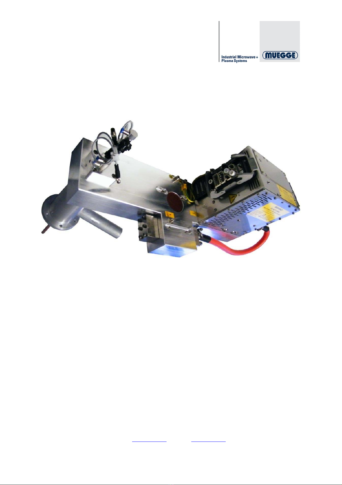
4.4 Overview of the components.......................................................................................................... 17
4.4.1 Legend of the components......................................................................................................... 19
4.5 Installation and assembly................................................................................................................ 20
4.6 Storage and protection..................................................................................................................... 21
4.7 User qualifications............................................................................................................................. 21
4.7.1 Operating personnel..................................................................................................................... 21
4.7.2 Maintenance personnel............................................................................................................... 22
4.7.3 Service personnel......................................................................................................................... 22
4.8 Where to store the instructions ..................................................................................................... 22
5. OPERATING INSTRUCTIONS ......................................................................... 22
5.1 Operation of the magnetron head ................................................................................................. 22
6. PROTECTION OF PERSONS .......................................................................... 23
7. MAINTENANCE AND CLEANING.................................................................... 23
7.1 Safety precautions............................................................................................................................. 23
7.2 Troubleshooting, diagnosis and measures................................................................................ 24
7.3 Maintenance plan for the operating and maintenance staff................................................... 24
7.4 Maintenance work for the maintenance staff ............................................................................. 25
7.4.1 Replacing the magnetron unit................................................................................................... 25
7.4.2 How to replace the magnetron unit.......................................................................................... 26
7.4.3 Replacing the antenna................................................................................................................. 27
7.4.4 How to replace the antenna........................................................................................................ 28
8. MAINTENANCE AND REPAIR BY THE CUSTOMER SERVICE .................... 29
8.1 Maintenance cycles for safe operation........................................................................................ 29
8.2 Contact details for our Customer Service................................................................................... 29
9. LIST OF SPARE PARTS AND CONSUMER GOODS ..................................... 30
10. APPENDIX .................................................................................................... 31
10.1 Table of illustrations......................................................................................................................... 32

Roth & Rau Muegge GmbH – Hochstraße 4-6 – 64385 Reichelsheim
Tel.: +496164 9307 0 – Fax: +496164 9307 93
MH3000S-211CV00008100102.doc
- 4 -
10.2 Circuit diagram................................................................................................................................... 33
10.3 Data sheets.......................................................................................................................................... 34

Roth & Rau Muegge GmbH – Hochstraße 4-6 – 64385 Reichelsheim
Tel.: +496164 9307 0 – Fax: +496164 9307 93
MH3000S-211CV00008100102.doc
- 5 -
1. Identification
1.1 Product brand and type designation
Product brand: Magnetron head
Type designation: MH3000S-211CV
Version: 000
Revision: 01
1.1.1 Rating plate
The rating plate identifies the system and also displays any customizations if applicable.
The rating plate is attached on the side of the casing above the water connections.
It contains the following technical data:
Type designation
Version
Revision
Serial number
1.2 Document identification
Validity of the documentation:
MH3000S-211CV00008100102
Version: 03/2011
1.3 Manufacturer's data
Manufacturer: Roth & Rau Muegge GmbH
Hochstraße 4-6
64385 Reichelsheim
Germany
Tel.: +496164 9307 0
Fax: +496164 9307 93
E-mail: [email protected]
Internet: www.muegge.de

Roth & Rau Muegge GmbH – Hochstraße 4-6 – 64385 Reichelsheim
Tel.: +496164 9307 0 – Fax: +496164 9307 93
MH3000S-211CV00008100102.doc
- 6 -
1.4 EC Declaration of Incorporation
The manufacturer: Roth & Rau Muegge GmbH,
Hochstraße 4-6
D-64385 Reichelsheim
Germany
Tel.: +49(0)6164 9307-0
Fax: +49(0)6164 9307-93
Web: www.muegge.de
hereby declares that the following product:
product designation: Magnetron head
consisting of:
Type designation Serial number Year of
manufacture
MH3000S-211CV 2011
complies with the basic requirements of the Machine Directive (2006/42/EC):
Appendix I, Articles 1.1.2, 1.1.3, 1.1.5, 1.3.2, 1.3.4 and 1.5.1.
The partly completed machine moreover complies with all requirements of the
Electrical Equipment Directive (2006/95/EC) and the Electromagnetic
Compatibility Directive (2004/108/EC).

Roth & Rau Muegge GmbH – Hochstraße 4-6 – 64385 Reichelsheim
Tel.: +496164 9307 0 – Fax: +496164 9307 93
MH3000S-211CV00008100102.doc
- 7 -
The following harmonized standards were applied:
DIN EN ISO 12100-1 Safety of machinery - Basic concepts, general principles for
design, Part 1: Basic terminology, methodology
DIN EN ISO 12100-2 Safety of machinery - Basic concepts, general principles for
design, Part 2: Technical principles and specifications
DIN EN 60204-1 Safety of machinery - Electrical equipment of machines,
Part 1: General requirements
The partly completed machine must not be put into service until such time as the
machine into which the partly completed machine is to be incorporated has been
declared to be in conformity with the provisions of the Machine Directive
(2006/42/EC).
The manufacturer undertakes to electronically transmit the specific documentation
regarding the partly completed machine to national authorities upon justified request.
The specific technical documentation associated with the machine in accordance with
Annex VII Part B has been compiled.
Name of the person authorized to compile the documentation: Boris Ihrig
Address of the person authorized to compile the documentation: see manufacturer's
address
Reichelsheim,
Date Signatory and information regarding the signatory
26.02.10 Klaus Muegge CEO

Roth & Rau Muegge GmbH – Hochstraße 4-6 – 64385 Reichelsheim
Tel.: +496164 9307 0 – Fax: +496164 9307 93
E-mail: [email protected]
2. Product description
2.1 Scope of application / General functions
Generation of microwaves
Use of microwaves in suitable applications
2.2 Intended use
The MH3000S-211CV magnetron head is used for the generation of microwaves and their
use in suitable applications.
The intended use includes your:
Being qualified to work on the MH3000S-211CV
Reading and observing these operating instructions
Complying with the technical data
Performing the maintenance works on time
CAUTIION
The MH3000S-211CV may only be operated in conjunction with
an appropriate MW power supply.
2.3 Dimensions
Dimensions and weight:
Dimensions: LxWxH in mm 550x200x395
Weight in kg 14.5
– Internet: www.muegge.de
MH3000S-211CV00008100102.doc
- 8 -

Roth & Rau Muegge GmbH – Hochstraße 4-6 – 64385 Reichelsheim
Tel.: +496164 9307 0 – Fax: +496164 9307 93
MH3000S-211CV00008100102.doc
- 9 -
2.4 Electrical data
Power circuit:
Type Size and unit
Mains voltage 400V AC
Mains frequency 50-60Hz
Mains current 500mA
Rated output 350VA
Mains tolerance ±10%
Control voltage circuit:
Type Size and unit
Mains voltage 24V DC
Mains frequency
Mains current 1.5A
Rated output 36VA
Mains tolerance ±10%
2.5 Microwave data
Type Size and unit
Anode voltage -5,100V DC
Anode current -1.45A
Frequency 2,450MHz
MW output (CW / Pulse) 3kW / 4.5kW-

Roth & Rau Muegge GmbH – Hochstraße 4-6 – 64385 Reichelsheim
Tel.: +496164 9307 0 – Fax: +496164 9307 93
MH3000S-211CV00008100102.doc
- 10 -
2.6 Cooling water
Type Value and unit
Flow 4 l/min.
Pressure 4 bar
Temperature 20 – 25°C
Connection Locking coupling S0GS
26KBAW17MPXS
Cooling water quality
Requirements for and care of the water in the cooling circuits!
Depending on the type of the system to be cooled, the cooling water must meet certain
requirements regarding its quality. In order to protect the system parts from corrosion and
deposits, Muegge GmbH on principle recommends that the water in closed circuits be treated
with a suitable agent (corrosion protection with non-ferrous metal protection and hardness
stabilisation). Moreover, in both open and closed circuits the following water qualities must be
observed subject to the materials installed, the temperature and the procedure.
Hydrological data Max. Unit
pH value 7.5 – 8.5 -
Conductivity <150 mS/m
Total hardness <15 °dH
Carbonate hardness <4 °dH
Carbonate hardness with hardness
stabilisation <20 °dH
Chloride Cl <100 mg/l
Sulphate So4 <150 mg/l
Ammonium NH4 <1 mg/l
Iron Fe <0.2 mg/l
Manganese <0.1 mg/l
Free of solids
Systems with aluminium: pH value min. 7.0 max. 8.0
Systems with stainless steel: Chloride Cl max. 100mg/l

Roth & Rau Muegge GmbH – Hochstraße 4-6 – 64385 Reichelsheim
Tel.: +496164 9307 0 – Fax: +496164 9307 93
MH3000S-211CV00008100102.doc
- 11 -
2.7 IP code / Plain text
The MH3000S-211CV magnetron head complies with protection class IP20.
Position Index
number Protection Explanation
First index
number 2 Against foreign bodies Protection against ingress of
foreign bodies with a diameter
exceeding 12.5mm.
Second index
number 0 No protection No water protection
2.8 Environmental conditions
Not in operation:
(Storage / Transport)
Drain water
Non-condensing
Temperature - 25°C - + 70°C, 70kPa – 106kPa
Relative humidity 80% up to 30°C,
afterwards linearly reduced to
50% at 45°C
In operation:
Temperature 5°C - 45°C
non-condensing, T max. = 45°C < 3h /
day
Relative humidity 80% up to 30°C,
afterwards linearly reduced to
50% at 45°C

Roth & Rau Muegge GmbH – Hochstraße 4-6 – 64385 Reichelsheim
Tel.: +496164 9307 0 – Fax: +496164 9307 93
E-mail: [email protected]
3. Safety information
MUST be read entirely
NOTE
Read this chapter entirely prior to starting work with the
MH3000S-211CV!
It contains important information for your personal safety.
This chapter must be read entirely and understood by all
persons working on this system in any product life cycle of
the MH3000S-211CV.
3.1 Residual hazards
The MH3000S-211CV is state-of-the-art and was built in consideration of the recognized
safety-related regulations. The MH3000S-211CV was subjected to a thorough safety test and
safety approval.
Nevertheless, residual hazards cannot be excluded regarding the use of the MH3000S-
211CV.
Hazards exist:
For life and limb of the operator
For the MH3000S-211CV and other material assets
Therefore it is required that all activities in connection with the MH3000S-211CV be carried
out by trained personnel in accordance with the information contained within these operating
instructions. The technical data must be observed as a matter of principle.
3.2 Responsibility
Areas of responsibility of Roth & Rau Muegge GmbH
Roth & Rau Muegge GmbH is responsible for the safety of the MH3000S-211CV. This is
based on the presupposition that the MH3000S-211CV has not been modified in any way
following the final acceptance.
Operator's areas of responsibility
The operator is responsible for the safety in the area surrounding the MH3000S-211CV.
Moreover, it is the operator's responsibility to ensure that the general safety regulations are
complied with for all works on the MH3000S-211CV.
– Internet: www.muegge.de
MH3000S-211CV00008100102.doc
- 12 -

Roth & Rau Muegge GmbH – Hochstraße 4-6 – 64385 Reichelsheim
Tel.: +496164 9307 0 – Fax: +496164 9307 93
E-mail: [email protected]
3.3 General safety regulations
3.3.1 Personnel
All persons working on the MH3000S-211CV must be technically qualified and trained
accordingly. They must be aware of all hazards and risks associated with the MH3000S-
211CV.
3.3.2 Notes and alerts within these operating instructions
The hazards and alerts within these operating instructions are basically divided into four
levels.
HAZARD
HAZARD marks an immediate hazard with high risk which will
result in death or severe physical injury if not avoided.
CAUTION
CAUTION marks a potential hazard with medium risk which may
result in death or severe physical injury if not avoided.
ATTENTION
ATTENTION marks a hazard with low risk which might result in
minor or medium-grade physical injury or damage to property if not
avoided.
NOTE
A note such as this one points to particularly important, however
not immediately hazardous information.
– Internet: www.muegge.de
MH3000S-211CV00008100102.doc
- 13 -

Roth & Rau Muegge GmbH – Hochstraße 4-6 – 64385 Reichelsheim
Tel.: +496164 9307 0 – Fax: +496164 9307 93
E-mail: [email protected]
3.3.3 Threshold values for the microwave stray radiation
According to current knowledge and until the completion of the research currently being
conducted in several countries, the microwave stray radiation density must not exceed 50
Wm-2 (5mWcm-2)at a distance of 0.05m from any accessible system part under normal
operating conditions.
Moreover, the power density of 100Wm-2 at a distance of 0.05m from any accessible point
of the system part must not be exceeded under conditions referred to as "exceptional
operation".
HAZARD
Persons must not be exposed to microwave energy radiated by
the microwave generator.
3.3.4 Improper use
Any use of the MH3000S-211CV deviating from the uses described in 2.1 and 2.2 is
prohibited. Improper use may result in hazards.
3.3.5 Service and maintenance works
All works on the MH3000S-211CV may only be carried out by persons who, based on their
technical qualifications, knowledge and professional experience, as well as knowledge of the
relevant regulations, are able to assess and execute the work to be performed and are able to
recognize the potential risks.
For any type of work the following principle must absolutely be observed:
ONLY WORK ON A SYSTEM THAT HAS BEEN DISCONNECTED FROM THE MAINS
In order to ensure proper disconnection from the mains, the following safety regulations must
be observed.
Disconnect from the mains
Secure against restarting
Ensure that the system has been properly disconnected
Earth and short-circuit
Cover or make inaccessible nearby live parts
3.3.6 Modifications
Any modifications require the written consent of the manufacturer.
– Internet: www.muegge.de
MH3000S-211CV00008100102.doc
- 14 -

Roth & Rau Muegge GmbH – Hochstraße 4-6 – 64385 Reichelsheim
Tel.: +496164 9307 0 – Fax: +496164 9307 93
MH3000S-211CV00008100102.doc
- 15 -
3.3.7 Interlock
The safety of systems of this application class is based on the principle of single-error safety.
In other words, if an error occurs, the safe condition must persist and the system turns off.
Microwave systems are equipped with at least two safety circuits working independently of
each other which allow for dual-channel monitoring.
In accordance with standard EN 60519-6, the following applies, among other things:
"When clearing an access opening of the microwave heating system, at least two microwave
interlocking devices (interlocking switch) of the microwave system must be activated with
elevated safety requirements and high reliability.
The failure of a mechanical or electrical interlocking device on access openings must set off
an alarm and deactivate the microwave system.
The failure of an electrical or mechanical component must not lead to all interlocking devices
for the access openings becoming ineffective.
At each opening, at least one microwave interlocking device must be covertly placed in such a
way that it cannot be operated with the aid of a human body part, neither during the open,
closed nor any intermediate position of the access opening."

Roth & Rau Muegge GmbH – Hochstraße 4-6 – 64385 Reichelsheim
Tel.: +496164 9307 0 – Fax: +496164 9307 93
MH3000S-211CV00008100102.doc
- 16 -
4. Preparation of the product for use
4.1 Transport and storage
The MH3000S-211CV is delivered on a conventional Euro pallet. The dimensions of the
MH3000S-211CV are LxWxH 550x200x395mm, and its weight is 14.5kg. The magnetron
head is initially wrapped in bubble wrap and packed in a transport box. Moreover, each edge
is equipped with an edge protector, and the transport box is strapped to the pallet with steel
straps.
The MH3000S-211CV is stored under specific conditions defined in Chapter 2.8.
4.2 Unpacking
First loosen the steel straps and then remove the edge protection and the bubble wrap.
The packaging material consists of metal, plastic and cardboard and must be disposed of
according to the applicable regulations.
4.3 Safety precautions prior to use
Ensure that the MH3000S-211CV is properly installed in the MW Power Supply Cabinets.

Roth & Rau Muegge GmbH – Hochstraße 4-6 – 64385 Reichelsheim
Tel.: +496164 9307 0 – Fax: +496164 9307 93
E-mail: [email protected]
4.4 Overview of the components
Figure 1
– Internet: www.muegge.de
MH3000S-211CV00008100102.doc
- 17 -

Roth & Rau Muegge GmbH – Hochstraße 4-6 – 64385 Reichelsheim
Tel.: +496164 9307 0 – Fax: +496164 9307 93
E-mail: [email protected]
Figure 2
– Internet: www.muegge.de
MH3000S-211CV00008100102.doc
- 18 -

Roth & Rau Muegge GmbH – Hochstraße 4-6 – 64385 Reichelsheim
Tel.: +496164 9307 0 – Fax: +496164 9307 93
MH3000S-211CV00008100102.doc
- 19 -
4.4.1 Legend of the components
A. Connecting plug to the mains
B. Water load
C. Cylinder
D. Coupling unit
E. Coax line with connecting flange
F. Outer tube
G. PE connection
H. Isolator
I. Operating hours meter
J. Connecting plug to the coupling unit
K. Magnetron unit
L. Air connection
M. Water connections for the water load
N. Reflexion measurement amplifier
O. Connecting plug to the magnetron unit
P. Water connection for the magnetron unit
Q. Water connection for the magnetron unit
R. Ventilator
S. Loop coupler for power measurement
T. Loop coupler for reflexion measurement

Roth & Rau Muegge GmbH – Hochstraße 4-6 – 64385 Reichelsheim
Tel.: +496164 9307 0 – Fax: +496164 9307 93
E-mail: [email protected]
4.5 Installation and assembly
The assembly of the MW Power Supply may only be carried out by qualified personnel.
Magnetron heads and their waveguides and / or coaxial conductors must be tightly bolted
together with the application. No leakage radiation must escape to the outside! (Chapter
Security)
After having checked the tight fitting of the magnetron heads, the cooling of the devices must
first be ensured.
In the case of air-cooled devices (magnetron heads / power supplies) cooling (insofar as no
other information is given) is effected internally via ventilators!
In the case of water-cooled devices (magnetron heads / power supplies) the water circuit must
be set up! The water inlet is marked IN and the water outlet is marked OUT. The required
amount for this purpose is defined in the Chapter Cooling Water. Following the setting up of
the cooling circuit, the latter must be inspected for its water-tightness.
NOTE
The plug connections of the cooling circuits may only be
connected or disconnected, at zero pressure.
The ingress of water into the devices (magnetron heads /
power supplies) as well as the condensation of the cooled
components in the devices must be prevented!
Only upon completion of the above steps can the electrical connection between the power
supplies and the magnetron heads be established!
The electrical connection must be established in accordance with the installation plan!
The connection cables must be in impeccable condition!
Pay attention to the Chapter "Security", as voltages of several thousand V occur in
microwave systems!
Finally the MW Power Supply is connected to the mains! In order to do so, the earth wire must
first be connected! Proceed according to the installation plan!
Prior to turning on the system, the individual points must be checked once more!
– Internet: www.muegge.de
MH3000S-211CV00008100102.doc
- 20 -
Table of contents