12 13
The instructions and warnings in this manual refer exclusively
to the muli and are not transferable to other bicycles. This
manual does not impart the skills of professional bicycle
mechanic. If you want to make changes to the basic equip-
ment of the muli, consult professional bicycle repair shop
and have these changes professionally checked.
Note that this manual cannot teach you how to ride cargo
bike like the muli. To learn how to ride the muli, proceed gent-
ly. Practice riding on calm and trac-free paths until you feel
condent and can keep the muli under control.
The company muli-cycles GmbH is not liable for errors or omissions in this docu-
ment. No liability or warranty is assumed if the muli is used beyond the intended
use. Warranty and liability are void in case of non-observance of the safety inst-
ructions, overloading, assembly errors, accidents, intentional misconduct, as well
as non-compliance with the specications for maintenance and care.
General safety instructions
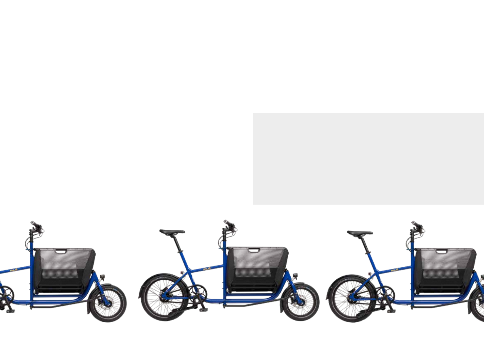
The muli is primarily bicycle for urban areas. It is therefore designed for use on
paved bike paths where the tires remain in constant contact with the ground. It is
not suitable for rough terrain, high-speed descents, jumps or riding with extreme
lateral positions. Please adhere to this usage recommendation, otherwise you risk
exceeding the load limits of the muli and causing damage to the frame, basket and
fork. The information on maintenance and repair as well as the proper operation of
the muli in this manual are part of the intended use.
In case you use the muli for commercial purposes, keep in mind that you expose
the muli to increased loads. This increased load may shorten the maintenance in-
tervals specied in this manual.
Intended Use
Adhere to this usage recommendation for intended use, other-
wise you risk exceeding the load limits of the muli and causing
damage to the frame, basket and fork. In addition, use not in
accordance with the intended use will result in the loss of all
warranty claims.
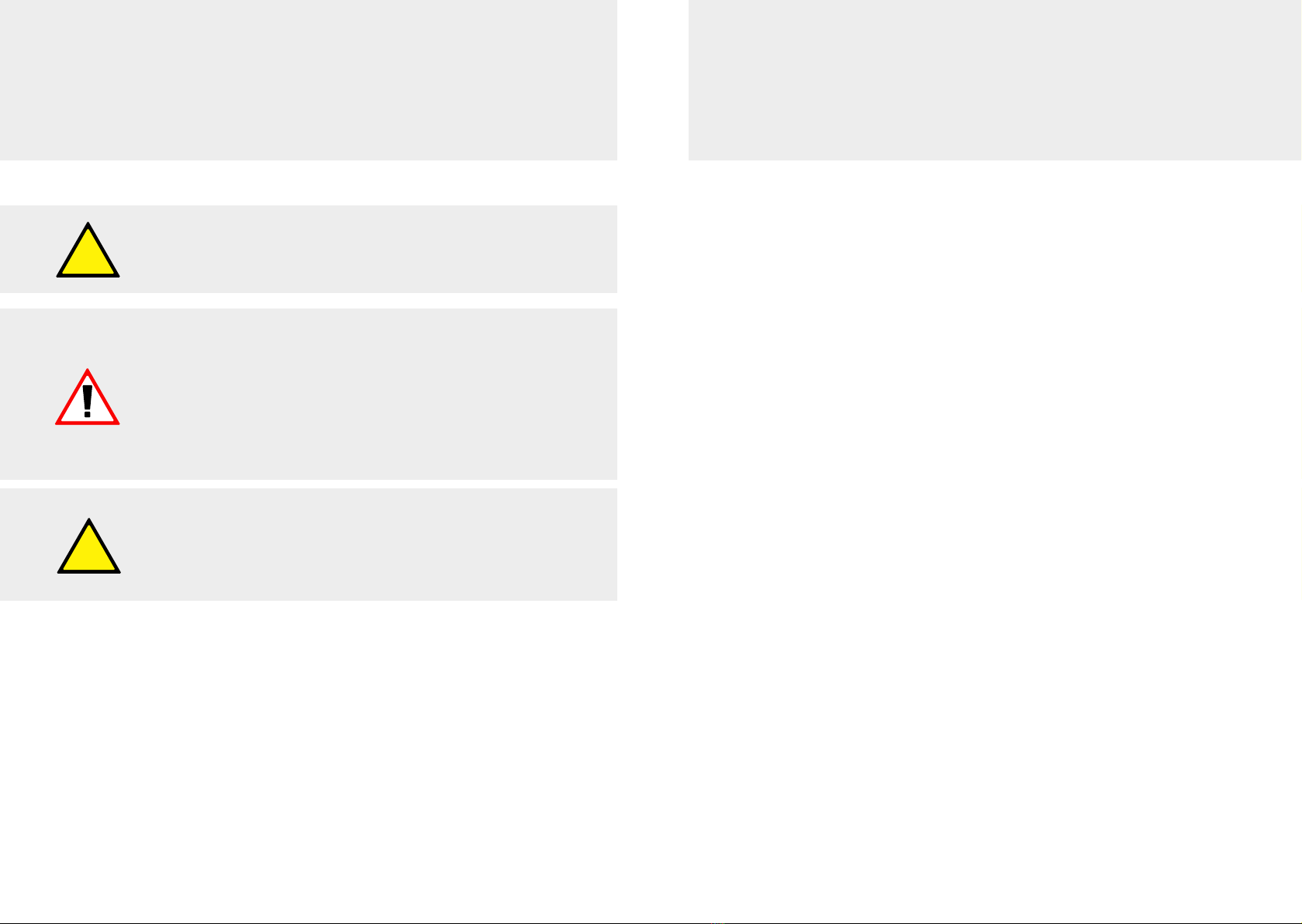
Caution!
Indicates information that requires special attention.
Warning!
Warns you of misconduct that may result in minor perso-
nal injury and property damage.
Danger!
Indicates possible serious personal injury
up to death
Danger of burning!
The temperature is above 45° (coagulation of protein)
and can cause burns in humans.
Symbols used in this Manual
Even for commercial use, be sure to observe the load limits spe-
cied in this manual, on frames and components if applicable.
Also and in particular for commercial use, the checks mentio-
ned in the chapter „Before each trip“ must be performed before
each trip. This will ensure that you notice increased wear or pos-
sible damage due to intensive use in good time.