8
OPERATING MANUAL FOR TEMPERATURE CONTROLLER
POWER
The power button is used to switch on/off the
conditioner. When the power is switched to “on”, the air-
conditioner will operate according to the standard setting
(temperature=25 degree celsius.)
TEMPERATURE
The TEMP+ and TEMP- buttons are used to adjust
the temperature setting which can be set in the range of
15-40°C. When the button is pressed, the control unit will
display the setting temperature (blinking), instead of the
room temperature. After setting is complete, it will resume
display of the room temperature within 4 seconds.
FAN
Fan speed (High, Medium, Low) can be altered using
the FAN button.
AUTO START
When the air-conditioner is “off” you can program
the unit to start by pressing the TIMER button. When you
press the TIMER button, the gure will change from “0” to
1 to 2 and up to 12 hours. Once you have set the timer, the
controller will count down until the time is “0”, and then the
controller will automatically turn on the air-conditioner.
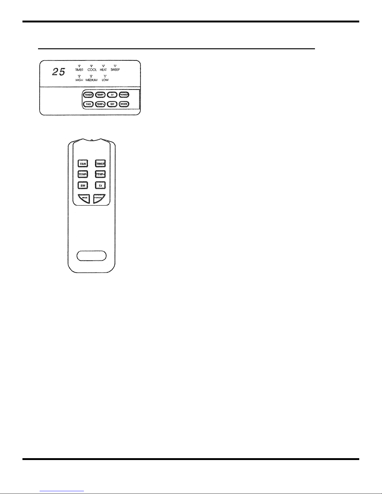
CONTROLLER TYPE WIRE
CONTROLLER TYPE WIRELESS
AUTO STOP
When the air conditioner is “on” you can program the unit to stop by pressing the TIMER button. When
you press the timer button, the gure will change from “0” to 1 to 2 up to 12 hours. Once you have set the
TIMER, the controller will count down until the time is “0” and then automatically turn off the air-conditioner.
MODE
This control allows you to operate the unit in different ways: Cool, Fan and Heat. When the control
operates in Cool mode, the COOL LED lights. When the control operates in Heat mode, the HEAT LED lights.
When the control operates in Fan mode, both the COOL and HEAT LEDs are off.
SWEEP
Switch the swing motor on and off. When the sweep is “on” it will cause the ari stream from the unit to
sweep back and forth.
LV
The LV button can be used to adjust the direction of air stream coming from the unit.