Multiaqua MHWW-36-H-1 User manual

2-Pipe Heat / Cool Fan Coil 36,000 BTUH
Hi-Wall Fan Coil
MHWW-36-H-1 Chilled/Hot Water

Heat/Cool
36 = 36,000
Available Model Numbers
MHWW-36-H-1
MHWW NOMENCLATURE BREAKDOWN
2-Pipe Heat/Cool
2-Pipe Heat/Cool Hi-Wall Fan Coil
MHWW- 36 - H -1
Voltage
1= 208/230/-1-50/60
Nominal BTUH

HVAC Guide Specifications
Chilled and Hot Water Hi-Wall Fan Coil
2-Pipe
Nominal Size:
36,000 BTUH
Multiaqua Model Number:
MHWW-36-H-1
Part 1-General
1.01 System Description
Multiaqua Chilled Water Fan Coils are manufactured with high impact molded polymers.
1.02 Quality Assurance
A. Certified in accordance with U.L. Standard 95, latest version (U.S.A.)
B. Manufactured in a facility registered to ISO 9002, Manufacturing Quality Standard.
C. Fully load tested at the factory.
D. Damage resistant packaging.
1.03 Delivery, Storage and Handling
A. Packaged and readied for shipment from the factory.
B. Controls shall be capable of withstanding 150°F storage temperatures in the control compartment.
C. Stored and handled per manufacturer’s recommendations.
Part 2-Product
2.01 Equipment
A. General:
1. Unit shall be a factory assembled and tested chilled and hot water fan coil.
2. Shall be assembled with high quality.
3. Contained with the unit shall be all factory wiring, piping, associated controls and special
accessories required prior to start up.
B. Unit Cabinet:
1. Composed of high impact polymers.
2. Shall be internally insulated to insure quiet operation.
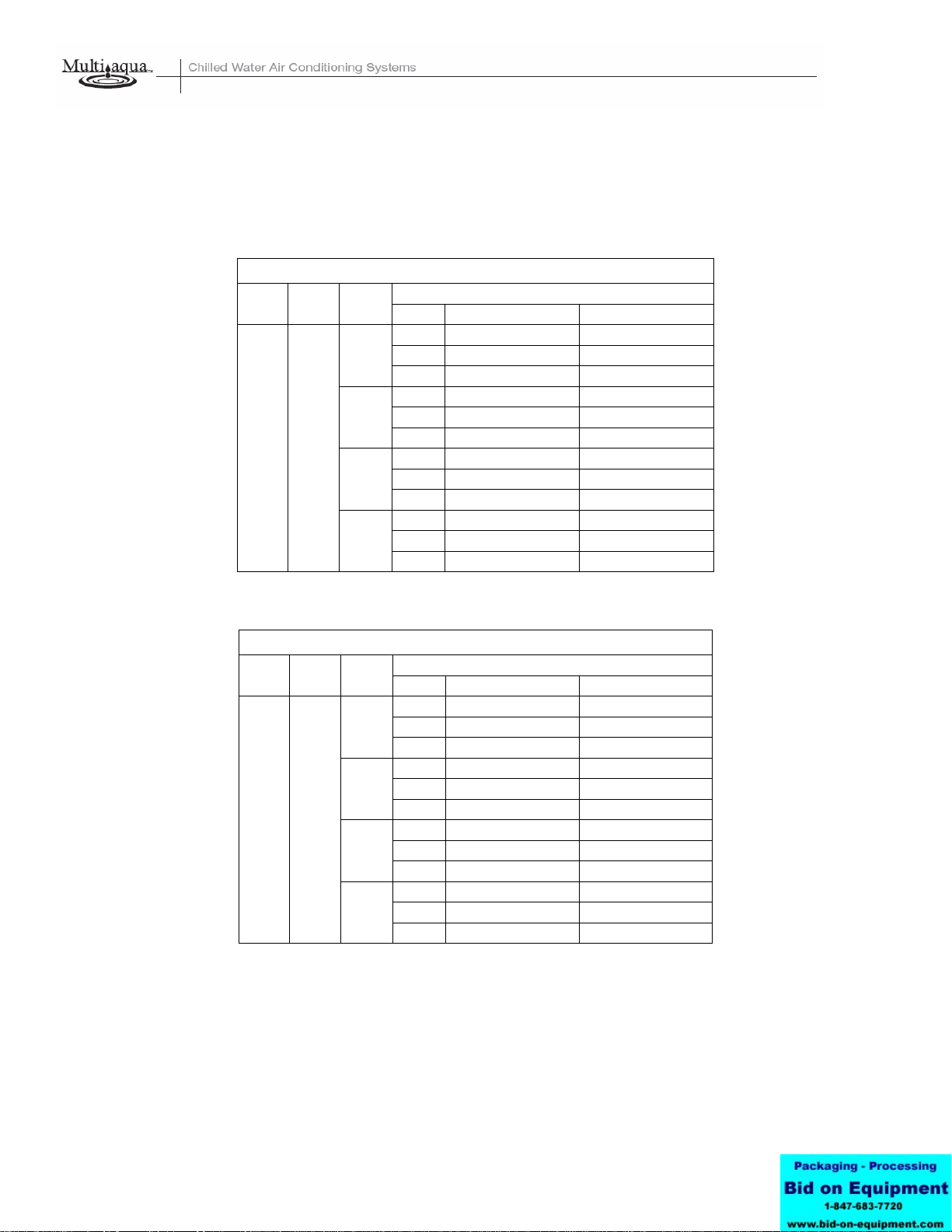
C. Fan Motors:
1. Shall be available in 208/230-1-50/60 vac.
1. Fan motors shall be three speed, direct drive, and PSC type.
2. Totally enclosed.
3. Internal overload protected.
4. Unit shall contain a swing motor to modulate the discharge air.
D. Blower Wheels:
1. Blower wheels are tangential and dynamically balanced.
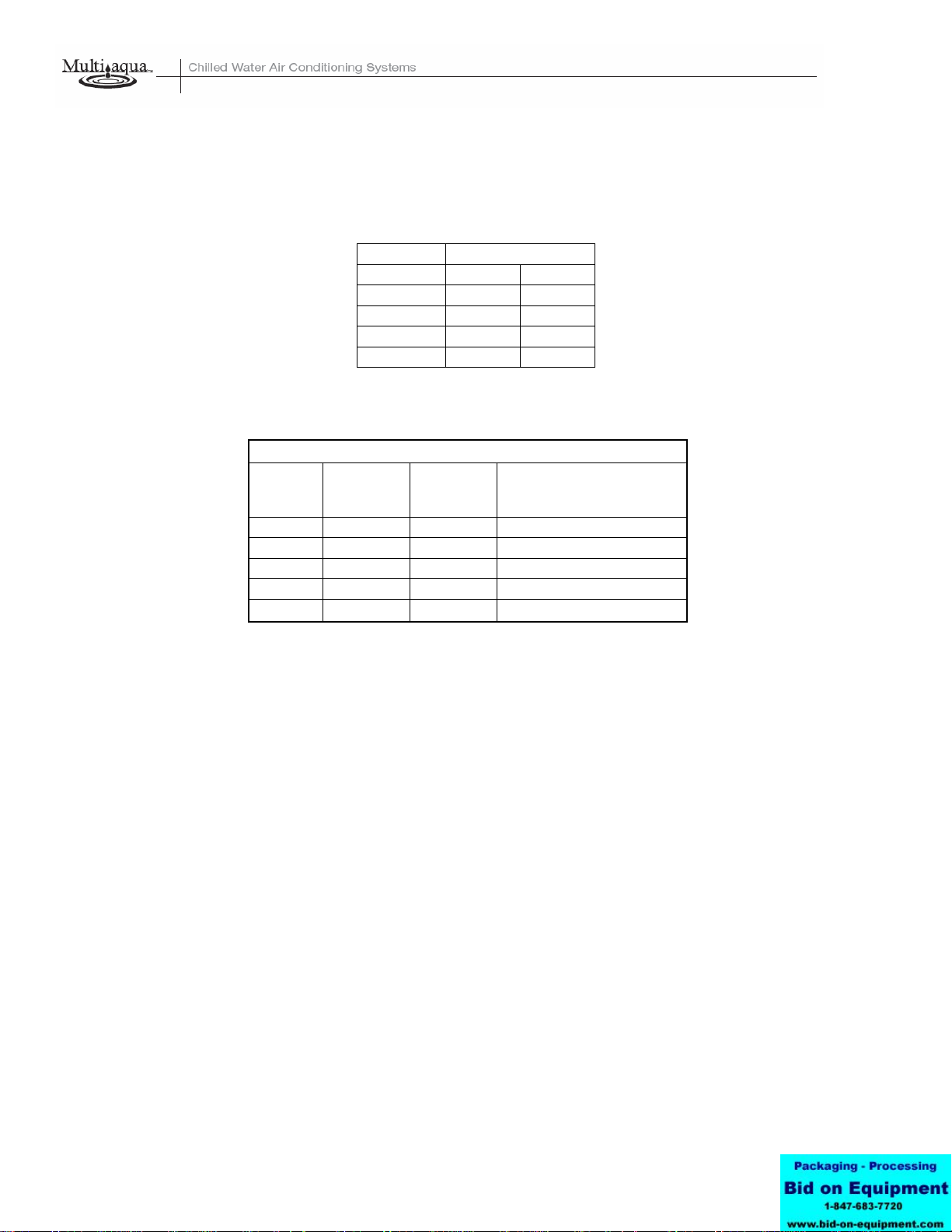
E. Water Coil:
1. Manufactured with water coils containing 3/8” copper tubing mechanically bonded to aluminum
fins.
2. Coils shall be factory tested to 350 psig.
F. Drain Pan:
1. All drain pans shall be molded with high impact polymers.
2. The exterior of all drain pans shall be insulated with closed cell to prevent condensation.
3. Pans shall contain a flexible drain tubing that is accessible from the back of the unit.
G. Filters:
1. Unit shall contain 65% washable filters.

Part 3-Controls and Safeties
3.01 Controls
A. Fan coils shall be completely factory wired and tested.
B. Controls shall include a circuit board, room sensor, indoor coil thermistor, transformer and wireless
remote.
C. Controls are capable of incorporating an optional Multiaqua hard-wired thermostat.
D. Controls shall be capable of controlling the 2-pipe fan coil on a 4-pipe hydronic system. Contact factory
for piping and wiring layouts.
3.02 Safeties:
A. Fan coil shall contain a non reusable fuse on the secondary voltage side of the transformer.
B. Discharge air sensor.
Part 4-Operating Characteristics:
4.01 Electrical Requirements
A. Unit shall incorporate a three prong male primary electrical power cord.
B. Electrical power supply shall be rated to withstand 120°F operating ambient temperatures.

MHWW-36-H-1 Product Specifications
Physical Data
Model Number Height
(in) Length (in) Depth
(in) Weight
(lbs)
Cooling
Rows
FPI
Copper
Diameter
(in)
Water
Inlet
(in)
Water
Outlet
(in)
Drain
(in)
MHWW-36-H-1 14.25 56.50 8.37 50.50 3-18 3/8 3/4 3/4 3/4
Electrical Data Fuse or HACR
Circuit Breaker
Per Circuit
Model Number Hi
Speed
CFM
Volts/ Phase/
Hertz Motor
HP Full Load
Ampacity Minimum
Amps Maximum
Amps
MHWW-36-H-01 850 208/230-1-50/60 1/12 0.42 .53 1
These specifications are subject to change without notice.

MHWW-36-H-1 Chilled Water Performance Data
MHWW-36 COOLING CAPACITIES
ENTERING AIR TEMPERATURE (°F)
CFM EWT
(°F) GPM 80° D.B. / 67° W.B. 75° D.B. / 63° W.B.
TC 33.8 25.9
SC 24.6 21.6
7.2 WPD 11.8 11.8
TC 34.6 26.5
SC 24.8 21.8
8.0 WPD 13.7 13.7
TC 35.4 27.0
SC 25.1 22.0
9.0 WPD 15.8 15.8
TC 36.0 27.5
SC 25.4 22.2
850 42
10.0 WPD 17.9 17.9
MHWW-36 COOLING CAPACITIES
ENTERING AIR TEMPERATURE (°F)
CFM EWT
(°F) GPM 80° D.B. / 67° W.B. 75° D.B. / 63° W.B.
TC 31.1 23.7
SC 23.5 20.8
7.2 WPD 11.8 11.8
TC 31.8 24.3
SC 23.8 21.0
8.0 WPD 13.7 13.7
TC 32.4 24.8
SC 24.0 21.2
9.0 WPD 15.8 15.8
TC 33.0 25.2
SC 24.3 21.3
850 45
10.0 WPD 17.9 17.9
These specifications are subject to change without notice.

MHWW-36-H-1 Hot Water Performance Data
MHWW-36 HEATING CAPACITIES
ENTERING ENTERING WATER TEMPERATURE (°F)
AIR (°F) CFM GPM WPD 100° 110° 120° 130° 140° 150° 160° 170° 180° 190° 200°
7.0 11.8 39.7 47.7 55.6 63.6 71.5 79.5 87.4 95.4 103.3 111.3 119.2
8.0 13.7 40.1 48.1 56.2 64.2 72.2 80.2 88.3 96.3 104.3 112.3 120.3
9.0 15.8 40.5 48.5 56.6 64.7 72.8 80.9 89.0 97.1 105.2 113.3 121.4
50 850
10.0 17.9 40.8 48.9 57.1 65.2 73.4 81.5 89.7 97.8 106.0 114.1 122.3
MHWW-36 HEATING CAPACITIES
ENTERING ENTERING WATER TEMPERATURE (°F)
AIR (°F) CFM GPM WPD 100° 110° 120° 130° 140° 150° 160° 170° 180° 190° 200°
7.0 11.8 31.8 39.7 47.7 55.6 63.6 71.5 79.5 87.4 95.4 103.3 111.3
8.0 13.7 32.1 40.1 48.1 56.2 64.2 72.2 80.2 88.3 96.3 104.3 112.3
9.0 15.8 32.4 40.5 48.5 56.6 64.7 72.8 80.9 89.0 97.1 105.2 113.3
60 850
10.0 17.9 32.6 40.8 48.9 57.1 65.2 73.4 81.5 89.7 97.8 106.0 114.1
MHWW-36 HEATING CAPACITIES
ENTERING ENTERING WATER TEMPERATURE (°F)
AIR (°F) CFM GPM WPD 100° 110° 120° 130° 140° 150° 160° 170° 180° 190° 200°
7.0 11.8 23.8 31.8 39.7 47.7 55.6 63.6 71.5 79.5 87.4 95.4 103.3
8.0 13.7 24.1 32.1 40.1 48.1 56.2 64.2 72.2 80.2 88.3 96.3 104.3
9.0 15.8 24.3 32.4 40.5 48.5 56.6 64.7 72.8 80.9 89.0 97.1 105.2
70 850
10.0 17.9 24.5 32.6 40.8 48.9 57.1 65.2 73.4 81.5 89.7 97.8 106.0
MHWW-36 HEATING CAPACITIES
ENTERING ENTERING WATER TEMPERATURE (°F)
AIR (°F) CFM GPM WPD 100° 110° 120° 130° 140° 150° 160° 170° 180° 190° 200°
7.0 11.8 15.9 23.8 31.8 39.7 47.7 55.6 63.6 71.5 79.5 87.4 95.4
8.0 13.7 16.0 24.1 32.1 40.1 48.1 56.2 64.2 72.2 80.2 88.3 96.3
9.0 15.8 16.2 24.3 32.4 40.5 48.5 56.6 64.7 72.8 80.9 89.0 97.1
80 850
10.0 17.9 16.3 24.5 32.6 40.8 48.9 57.1 65.2 73.4 81.5 89.7 97.8
These specifications are subject to change without notice.

MHWW-36-H-1 Capacity and Glycol Adjustments
CAPACITY CORRECTION FACTORS
MODEL # MHWW-36-H-1
CFM TC SC
675 .82 .80
700 .85 .82
750 .91 .88
825 .98 .95
Propylene Glycol & GPM Adjustment Factors
Ambient
Temp
Propylene
Glycol % Capacity
Reduction GPM Adjustment =
100% Capacity
26° F 10% x 0.99 x 1.01
20° F 20% x 0.98 x 1.03
8° F 30% x 0.98 x 1.07
-5° F 40% x 0.97 x 1.11
-28° F 50% x 0.96 x 1.16
Example:
30% Propylene Glycol Solution.
System capacity x 0.98
GPM x 1.07
These specifications are subject to change without notice

INSTALLATION & OPERATING
MANUAL
MHWW Hi-Wall Fan Coils
36,000 BTUH
MHWW CONTROLS OPERATION GUIDE
Wireless Control: Standard Control Package
Optional Wired Control: EG-003

INSTALLATION & OPERATING
MANUAL
MHWW Hi-Wall Fan Coils
36,000 BTUH
MHWW CONTROLS OPERATION GUIDE
Wireless Control:
Name and function of remote controller
Note:
•Be sure there are no obstructions between receiver and remote controller.
•The remote control signal can be received at the distance of up to about 21 feet.
•Do not throw or drop the remote controller.
•Do not put any liquid in the remote controller and do not put it in direct sunlight
or any place where it is very hot.
•Remove batteries when the remote controller is not in use for extended periods of
time.
•The remote controller should be placed 3 or more feet away from any electric
appliance.
LED MODE INDICATOR FOR REMOTE CONTROLLER:
INDICATOR
LIGHTS REMOTE
SETTING FUNCTION
RED-GREEN COOL COOLING OPERATION ONLY
RED-OFF DRY HUMIDITY CONTROL, WATER FLOW, NO FAN
RED-RED HEAT HEATING OPERATION ONLY
RED-OFF FAN FAN OPERATION ONLY
RED-BLINKING AUTO AUTO SELECTION BETWEEN HEAT & COOL
DEPENDENT ON ROOM TEMP & SET TEMP
RED-ORANGE ALERT FAN COIL WAITING FOR EWT TO REACH PROPER
TEMPERATURE NECESSARY TO SATISFY SET POINT

INSTALLATION & OPERATING
MANUAL
MHWW Hi-Wall Fan Coils
36,000 BTUH
MHWW CONTROLS OPERATION GUIDE
FUNCTION
1. TRANSMISSION SOURCE
- Infra red transmission source
2. POWER
- Press to turn the fan coil on and off or vice versa.
(Red LED left will light to indicate the control is on)
3. MODE
- To select desired operation mode.
It will switch from one to another as shown.
COOL - Cooling operation.
DRY - Humidity control.
HEAT - Heating operation.
FAN - Fan only. No cooling or heating capability.
AUTO - Operation mode will be selected automatically between HEAT and
COOL mode, depending upon the room temperature and SET temperature.
4. FAN
- To select fan speed. It will switch from one to another as shown below.
- When the system temperature sensor is not calling for cool or heat the fan will
run at the speed previously entered in fan mode selection (high, medium or low).
- If auto was the previously entered fan speed in cooling: The fan will run at low
speed until the temperature sensor calls for either heating or cooling at which
point the fan will return to auto speed control
Fan speed sequence

INSTALLATION & OPERATING
MANUAL
MHWW Hi-Wall Fan Coils
36,000 BTUH
MHWW CONTROLS OPERATION GUIDE
FUNCTION
5. TEMPERATURE SETTING
- Press “▲” to increase set temperature.
- Press “▼” to decrease set temperature.
- Press “▲” and “▼” Simultaneously to toggle between °C and °F display mode.
- Temperature range: 16°C to 30°C in °C display mode and 60°F to 86°F in °F
display mode.
6. DELAY TIMER SETTING
- The delay timer is capable of delaying both on and off functions. The delay
feature will take affect in all modes with the exception of the sleep mode. Each
time the “▲” and “▼” is pressed it increases or decreases the On or OFF set
point by 1 hour; up to a maximum of 18 hours.
To set the OFF DELAY:
-With the system in operation, enter the system OFF time by pressing the “▲”
button to the desired number of hours ahead that the system will be allowed to
run. When the number of hours entered has elapsed the system will turn off.
To set the ON DELAY:
- Set the on delay by entering the desired mode of operation (fan, heat, cool and
the appropriate temperature. This will be the settings the system will follow
when operation resumes. After setting the mode and any applicable
temperature with the control, turn the remote off. Now enter the number of
hours to elapse before operation resumes by pressing the “▲” button on the
remote to the desired number. When the time (in hours) entered has elapsed,
the system will resume operation according to the pre-set mode and
temperature.

INSTALLATION & OPERATING
MANUAL
MHWW Hi-Wall Fan Coils
36,000 BTUH
MHWW CONTROLS OPERATION GUIDE
7. CANCEL
- To cancel any setting on the delay timer.
8. LOUVER
- Two different functions are available:
1. To set the louver stop position. There are 4 angles available. The sequence is as
follows.
2. To set the louver swing (continuous motion). The sequence is as follows.
9. SLEEP
- This function when selected will allow the user to determine a “sleep” period. In
cooling the selected temperature will rise to 1°above set point in 1/2 hour,
rising to 2°in 1 hour, rising again to 4°after 2 hours of the SLEEP CYCLE.
SLEEP FUNCTION DISPLAY
10. DRY
- This function operates to control humidity within a conditioned space. It
measures the difference between set point and the actual room temperature.
An algorithm determines how far above set point the actual room temperature is
to set point temperature and selects periods of water valve operation and low fan
operation. The greater the difference between room temperature and set point
temperature prompts greater run time with less temperature. With less
temperature differences, periods of fan and valve operation are called for in
varying increments as determined by the difference. In this mode (low speed) fan
operation will start 30 seconds after valve has opened and stops 30 seconds after
valve has closed.

INSTALLATION & OPERATING
MANUAL
MHWW Hi-Wall Fan Coils
36,000 BTUH
MHWW CONTROLS OPERATION GUIDE
11. AUTO
- This function will automatically control the system switching between heating and
cooling operation. If the preset auto mode is cooling, a switch to heating
operation will begin only if the actual room temperature is 7°below selected
control set point. If the present auto mode is heating, a switch to cooling operation
will begin only when the room temperature is 3°above selected control set point.
12. TRANSMISSION INDICATOR
- Blinks twice to indicate that transmission has taken place between remote and
receiver.
- Beeps indicate fan coil acknowledging receipt of transmission.
TRANSMISSION INDICATOR
13. HOW TO INSERT BATTERIES
1. Remove the battery cover from the back of the remote.
2. Insert the (2) AAA batteries. Ensure that the polarity of the batteries are as shown
inside of the battery compartment.
3. Re-attach the battery compartment cover.

INSTALLATION & OPERATING
MANUAL
MHWW Hi-Wall Fan Coils
36,000 BTUH
MHWW CONTROLS OPERATION GUIDE
Optional Wired Control: EG-003
LED MODE INDICATOR FOR REMOTE CONTROLLER:
INDICATOR LIGHTS SETTING FUNCTION
RED-GREEN COOL COOLING OPERATION ONLY
RED-RED HEAT HEATING OPERATION ONLY
RED-BLINKING AUTO AUTO SELECTION BETWEEN HEAT & COOL
RED-OFF FAN FAN OPERATION ONLY
1. POWER
- Press to turn the fan coil on and off or vice versa.
2. MODE
- To select desired operation mode.
It will switch from one to another as shown.
COOL - Cooling operation.
HEAT - Heating operation.
FAN - Fan only. No cooling or heating capability.
AUTO - Operation mode will be selected automatically between HEAT and
COOL mode depending upon the room temperature and SET temperature.
3. FAN
- To select fan speed. It will switch from one to another as shown below.
- When the system temperature sensor is not calling for cool or heat the fan will run at
the speed previously entered in fan mode selection (high, medium or low).
- If auto was the previously entered fan speed in cooling: The fan will run at low speed
until the temperature sensor calls for either heating or cooling at this point the fan
will return to auto speed control
Fan Speed Sequence

INSTALLATION & OPERATING
MANUAL
MHWW Hi-Wall Fan Coils
36,000 BTUH
MHWW CONTROLS OPERATION GUIDE
FUNCTION
4. TEMPERATURE SETTING
- Press “▲” to increase set temperature.
- Press “▼” to decrease set temperature.
- Press “▲” and “▼” Simultaneously to toggle between °C and °F display mode.
- Temperature range: 16°C to 30°C in °C display mode and 60°F to 86°F in °F
display mode.
5. CANCEL
- To cancel any setting on the delay timer.
6. LOUVER
- Two different functions are available:
1. To set the louver stop position. There are 4 angles available. The sequence is as follows.
2. To set the louver swing (continuous motion). The sequence is as follows.
7. AUTO
- This function will automatically control the system switching between heating and
cooling operation. If the present auto mode is cooling, a switch to heating
operation will begin only if the actual room temperature is 7°below selected
control set point. If the present auto mode is heating, a switch to cooling operation
will begin only when the room temperature is 3°above selected control set point.

MHWW-36-H-1 Wiring Diagram
208/230/-1-50/60

MHWW-36-H-1 CERTIFIED DRAWING
Table of contents
Other Multiaqua Air Conditioner manuals
Popular Air Conditioner manuals by other brands

Retro Aire
Retro Aire R40C Installation, operation & maintenance manual

Carrier
Carrier Fan Coil 42B Installation, operation and maintenance manual

Pioneer
Pioneer FAB Series installation manual

Rotenso
Rotenso MIRAI W user manual

Daikin
Daikin Super Multi Plus E-Series CTXG50EV1BW user manual

Dometic
Dometic FreshWell3000 installation manual

Carrier
Carrier ASBFE600BA owner's manual

Admiral
Admiral AW-05CM1FLU use and care manual

Frigicoll
Frigicoll MKD-V300 Installation & owner's manual

GREE ELECTRIC
GREE ELECTRIC GWH09TA-S3DNA1C Service manual

Carrier
Carrier ROOM AIR CONDITIONER operating manual

Fuji Electric
Fuji Electric RD-60FA Service manual