Multiaqua MAC120 Series User manual


Page
1
2
3
4
5
6
7
8
9
10
11
13
15
17
34
43
44
45
46
48
50
56
57
74
83
84
85
86
88
89
94
99
100
101
102
113
116
117
118
119
121
122
127
132
133
134
145
147
Product Specifications
Nomenclature Breakdown
Guide Specifications
Installation and Operating Manual
Product Specifications
Capacities
Certified Drawing
Wiring Diagrams
Certified Drawing
Installation and Operating Manual
Guide Specifications
Capacity Adjustment Factors
Circulating Pump Curve
Table of Contents (Hydronic)
Multi-Zoning and Energy Cost
System Modeling Software
About Us
MAC120 Air-Cooled Chiller
Accessory Products Overview
Features and Benefits
Water Products Overview
DX Products Overview
Equipment Sound Data
Wiring Diagrams
Product Specifications
Capacities
Guide Specifications
MHCCW (Ceiling Concealed) 2-pipe Chilled Water with Electric Heat. 1 to 3 Tons
Nomenclature Breakdown
CFM and Glycol Adjustments
Certified Drawing
MAC036,048 and 060 Air Cooled Chiller
Chilled Water Capacities
CFM and Glycol Adjustments
Capacity Adjustment Factors
Product Specifications
Hot Water Capacities
Installation and Operating Manual
Wiring Diagrams
Chilled Water Capacities
Electric Heat Capacities
Hot Water Capacities
Installation and Operating Manual
Wiring Diagrams
Certified Drawing
Nomenclature Breakdown
MHNCCW (Ceiling Concealed) 4-Pipe Chilled and Hot Water. 1 to 3 Tons
Guide Specifications

Page
148
149
150
152
153
155
157
157
158
169
170
171
172
173
175
176
181
186
187
202
206
207
208
209
211
212
218
224
225
231
232
233
234
235
237
238
243
246
247
249
257
258
259
260
261
263
264
268
269
270
271
279
280
CFM and Glycol Adjustments
Capacity Adjustment Factors
CWA4 (Air Handler) 4-pipe Chilled and Hot Water 2 to 5 Tons
Guide Specifications
Product Specifications
Hot Water Capacities
Nomenclature Breakdown
Chilled Water Capacities
Installation and Operating Manual
Wiring Diagrams
Certified Drawing
MHWW (Hi-Wall) 2-Pipe Chilled and Hot Water. 1 to 3 Tons
Nomenclature Breakdown
Chilled Water Capacities
CFM and Glycol Adjustments
Capacity Adjustment Factors
Capacity and Glycol Adjustment Factors
Certified Drawing
Nomenclature Breakdown
Capacity and Glycol Adjustment Factors
Installation and Operating Manual
Wiring Diagrams
Certified Drawing
CFM and Glycol Adjustments
Table of Contents (Hydronic Continued)
MCCW (Ceiling Concealed) 2-Pipe Chilled and Hot Water. 4 to 5 Tons
Guide Specifications
Product Specifications
Hot Water Capacities
Chilled Water Capacities
Installation and Operating Manual
Guide Specifications
Product Specifications
Hot Water Capacities
Installation and Operating Manual
Chilled Water Capacities
Wiring Diagrams
CFFWA (Universal Mount) 2-Pipe Chilled and Hot Water. 1 to 5 Tons
Guide Specifications
Product Specifications
Hot Water Capacities
Installation and Operating Manual
Wiring Diagrams
Certified Drawing
CWA2 (Air Handler) 2-pipe Chilled Water with Electric Heat. 1.5 to 5 Tons
Guide Specifications
Product Specifications
Hot Water Capacities
Wiring Diagrams
Certified Drawing
Capacity Adjustment Factors

Page
281
282
283
285
287
288
289
300
304
305
306
307
309
309
309
310
316
317
318
319
320
322
323
323
323
324
325
330
341
343
344
345
346
348
348
349
363
371
372
373
374
376
376
377
383
384
Table of Contents (Direct Expansion)
CFM Adjustments
Nomenclature Breakdown
MHCCX (Ceiling Concealed) DX with Electric Heat. 1 to 3 Tons
Guide Specifications
Product Specifications
Capacities
Installation and Operating Manual
Wiring Diagrams
Certified Drawing
Nomenclature Breakdown
MHNCCX (Ceiling Concealed) DX with Hot Water. 1 to 3 Tons
Guide Specifications
Product Specifications
Capacities
Installation and Operating Manual
Wiring Diagrams
Certified Drawing
Wiring Diagrams
Installation and Operating Manual
Wiring Diagrams
Certified Drawing
Nomenclature Breakdown
MCCX (Ceiling Concealed) DX Only. 4 to 5 Tons
Capacities
Installation and Operating Manual
Wiring Diagrams
FSFCA (Universal Mount) DX Only. 1 to 5 Tons
Guide Specifications
Product Specifications
Capacities
Installation and Operating Manual
MHWX (Hi-Wall) DX Only. 1 to 3 Tons
Guide Specifications
Product Specifications
Certified Drawing
Nomenclature Breakdown
CFM Adjustments
CFM Adjustments
Glycol Adjustments
Capacity Adjustment Factors
Hot Water Capacities
Guide Specifications
Product Specifications
DX Capacities
Nomenclature Breakdown
Certified Drawing

Page
385
387
388
389
391
392
395
396
397
398
399
400
407
408
409Warranty Information
Sample Piping
Circulating Pump Curve (.5 HP)
Condensate Pump
Circulating Pumps (1,1.5 & 2 HP)
Circulating Pump Curve (1,1.5 & 2 HP)
Circulating Pumps (.5 HP)
Expansion Tank and Air Scoop
Liquid Solution Bypass Valve
Accessories
Storage Tanks
Banked Chiller Configuration
Table of Contents (Accessories)
Control Thermostats
Ceiling Concealed Enclosures
Liquid Solution Control Valves
Wye Strainer

About Us
Setting new industry standards is what we do best.
At Multiaqua, our commitment to creating innovative air conditioning products has made us one
of the most respected organizations in the industry. From concept to market, Multiaqua takes a
hands-on approach to ensure that each and every step meets our stringent standards of quality,
durability and dependability.
All Multiaqua products are designed with the future in mind. That’s why all air conditioning
products are flexible, which makes it easy to adapt to virtually all kinds of building applications.
Whether it’s residential or commercial air conditioning needs, Multiaqua has the products to
meet or exceed all expectations.
Manufacturing Excellence
Our beliefs in quality is more than just a practice, it is something we take great pride in. Our
quality management system is integrated with international quality requirements of ISO 9002.
That is why some of the biggest OEM names in the air conditioning industry use Multiaqua
products in their units. In fact, Multiaqua chillers were part of air conditioning system that won
first place awards in the Quality Home Comfort Awards Competition, which was created to
honor the best in residential comfort system design and application.
Our products are tested and certified to the UL, CE, ETL, UL1995 and ARI standards; the most
respected and stringent in the world.
Experience The Future
At Multiaqua, we invite you to come experience the future of air conditioning and see why more
and more companies are discovering the new standard of air conditioning excellence. And by
combining cost effectiveness, innovation and quality, Multiaqua will continue to provide air
conditioning products that will be the most sought after in the world.
1

Multiaqua Makes Hydronic System Design Easy
55°F
45°F
CH-1
117000 BTU/H
9.8TONS
24.5 GPM
(
50%
)
ICL-1
60000 BTU/H
12.6 GPM
55°
F
45°
F
ICL-
2
36000 BTU/H
7.6GPM
55°F
45°
F
ICL-3
24000BTU/
H
5 GPM
55°
F
45°
F
ICL-4
24000BTU/H
5 GPM
55°
F
45°F
ICL-
5
24000 BTU/
H
4.9GP
M
55.4°F
45°
F
ICL-6
30000 BTU/
H
6.3 GPM
55°
F
45°
F
ICL-7
36000 BTU/H
7.6 GPM
55°F
45°
F
ET-1
11.5GAL
P-1
49 GPM
66.7 FT
STOR-1
73.1GA
L
55°
F
45°
F
CH-2
117000BTU/
H
9.8 TONS
24.5 GPM
(
50%
)
1
"
1.25"
100'
1.25"
100' 1.25
"
145'
1.5"
1.5
"
1.25"145'
2"
1
"
1"
1.25
"
145' 1"
5'
1.5
"
145'
1"5' 1.5"
1' 1.25
"
5'
1.25"5'
1.5
"
145'
1"5'
1.5"1' 1.25"5'
1.25
"
5'
1
"
10'
2.5"
5'
1.25"
145' 1"
1"
2.5" 1'
0'
2.5"
0'
2.5
"
5'
2"
5'
2
"
5'
2
"
1'
NAME: MULTIAQU
A
LOCATION: SOUTH CAROLINA
BYPASS VALVE
Sample Design Shown
Introducing System Modeling Software
Multiaqua has teamed up with HVAC Solutions and would like to introduce the newest version of the HSS
Software. This software will contain a selection model that includes Mutiaqua’s Air Cooled Chillers, Fan Coils
and Air Handling Units.
HSS software will allow you to drag and drop components to design hydronic systems. It includes the necessary
piping, piping components and equipment. It is capable of exporting calculation reports, equipment schedules
and a bill of material. Visit www.multiaqua.com for software down load.
2

3

Ductless and Ducted Hydronic Air Conditioning & Heating Systems.
FOR MULTIZONING FACILITIES
•Zoning saves energy
•Better Control of Humidity
•Separate Climate in each Room
1. More Energy Efficient Thru Zoned Comfort Cooling.
2. Zoning Allows For Diversity.
3. Diversity and Load Calculations Allows For Reducing The Size of The Outdoor
Power Plant.
4. Banking Chillers Allows For Huge Efficiencies Thru Staging.
5. Helps Control The Growth Of Mold, Mildew and Fungus.
6. Low Installation Costs.
7. No Refrigerant Handling.
8. No Ductwork No Line Sets.
9. Heat & Cool with the Same Units.
10. No Line Length Limitations.
11. Unlimited Tonnage with Single Phase Power.
12. Easy To Expand System.
Think Water !!!
4

Page 44 Page 9
Page 84 Page 117
With or Without Electric Heat
Page 171 Page 148
Page 233
Page 207
Page 259
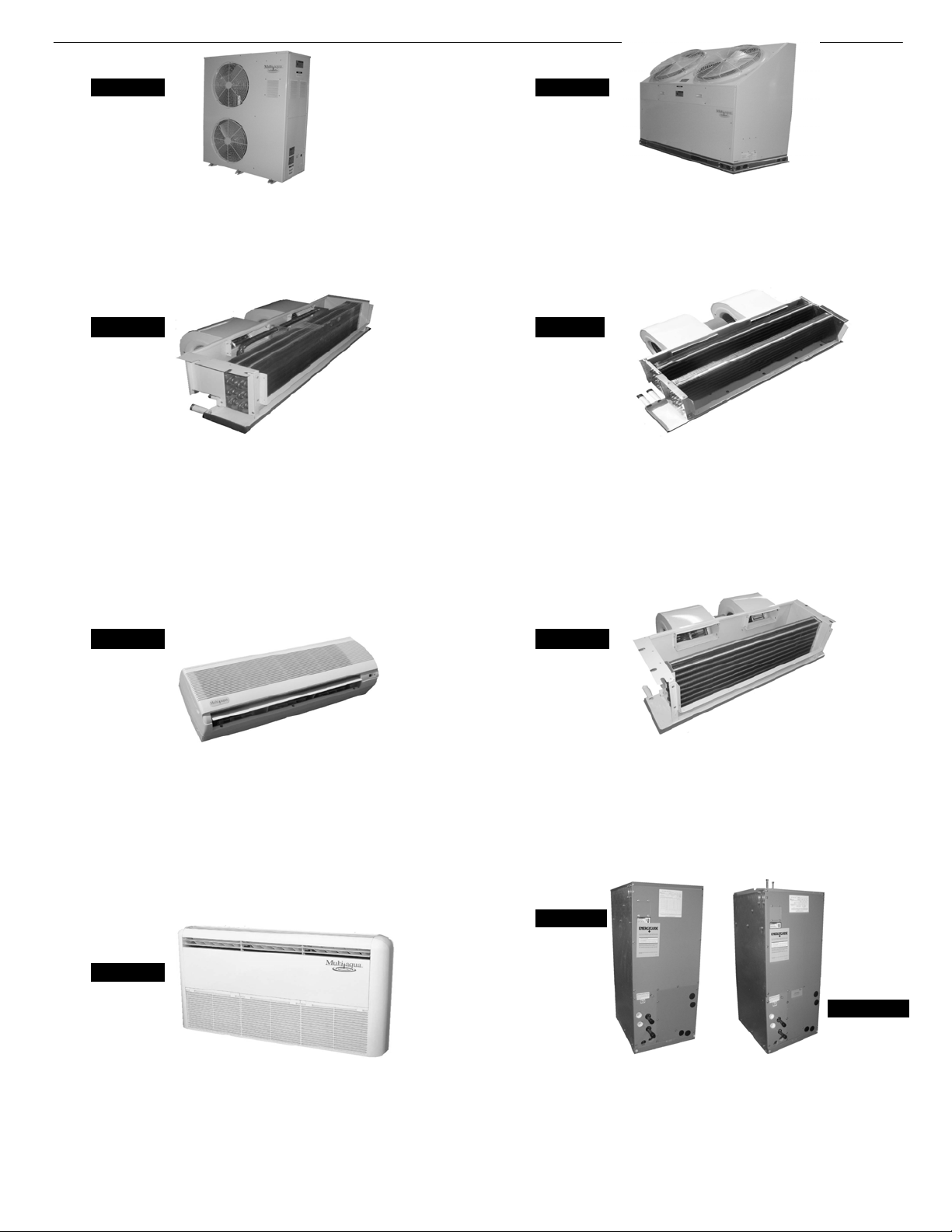
CWA2 With or Without Electric Heat 2-Pipe
CWA4 Chilled & Hot Water 4-Pi
p
e
• Available in 2 or 4-Pi
p
e Confi
g
uration
• 18
,
000- 60
,
000 BTUH
• Floor
,
Low Wall or Horizontal Ceilin
g
Mountin
g
• U
p
Flow
,
Left or Ri
g
ht Hand Horizontal Installatio
n
• E
q
ui
pp
ed with R4.2 Insulation
• CWA2 in 208/240-1-60 & CWA4 in 120-1-60
• Electric or Hot Water Heat
MHWW (Hi-Wall) Chilled/Hot Water 2-Pipe
• Powder Painted Galvanized Steel
• Discharge May be Ducted for Small Spaces
• Manual Air Vents
• Attractive Seamless Appliance Design
• Cleanable Air Filter Provided
• Heavy Gauge Metal Cabinet
• Manual Air Vents
• Powder Painted Galvanized Steel
• Double Field Reversible Hand of Connection Coil
• Discharge May be Ducted for Small Spaces
• Heavy Gauge Metal Cabinet
• Ceiling Concealed Design for Clean Installation
• Two Stages of Coolin
g
• Removes Equipment from Conditioned Space
MHNCCW (Ceiling Concealed) Chilled/Hot Water 4-Pipe
• Available with or without Electric Heat
• 12,000-36,000 BTUH
• Ceiling Concealed Design for Clean Installation
MCCW (Ceiling Concealed) Chilled/Hot Water 2-Pipe
• Removes Equipment from Conditioned Space
• 48,000 – 60,000 BTUH
• Ceiling Concealed Design for Clean Installation
• Horizontal Air Discharge
• 3, 4 & 5 Ton Air Cooled Chiller
• Field Reversible Hand of Connection Coil
• Heavy Gauge Metal Cabinet
• Stainless Steel Pump Included
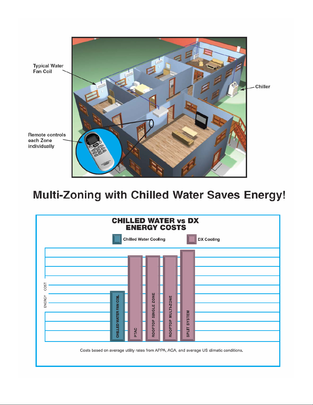
Water Product Overview
MAC036, 048 & 060 Air Cooled Chiller MAC120 Air Cooled Chiller
• R 407c Refrigerant
• 10 Ton Air Cooled Chiller
• R 407c Refrigerant • Copeland Scroll Compressor Technology• Copeland Scroll Compressor Technology
• Vertical Air Discharge
• 9,000- 36,000 BTUH
• High Wall Mounting
• Manual Air Vents
• Powder Painted Galvanized Steel
MHCCW (Ceiling Concealed) Chilled Water 2-Pipe
• Removes Equipment from Conditioned Space
• 12,000- 36,000 BTUH
• Discharge May be Ducted for Small Spaces
5
• Wired Controller Option
• Wireless Infrared Remote Included
• Attractive Modular Design
• Cleanable Air Filter Included
• Optional Wireless Remote
CFFWA Universal Mount Fan Coil 2-Pipe
• 12,000- 60,000 BTUH

MHCCX (Ceiling Concealed) DX 2-Pipe
6
• Heavy Gauge Metal Cabinet
MHNCCX (Ceiling Concealed) DX 4-Pipe
• Attractive Seamless Appliance Des
i
• Cleanable Air Filter Provided
FSFCA (Universal Mount) DX or Heat Pump
• 12,000- 60,000 BTUH
• TXV Provided
• Attractive Modular Design
• High Wall Mounting
•13 SEER Compatible
MCCX (Ceiling Concealed) DX
• Wired Control Option
• Wireless Infrared Remote Included
• Floor, Low Wall or Horizontal Ceiling Mounting
• Removes Equipment from Conditioned Space
• Discharge May be Ducted for Small Spaces
• Ceiling Concealed Design for Clean Installation
• Heavy Gauge Metal Cabinet
• Powder Painted Galvanized Steel • Cleanable Air Filter Included
• Optional Wireless Remote
•13 SEER Compatible
• 48,000-60,000 BTUH
• 9,000- 36,000 BTUH
• TXV Provided
MHWX (Hi-Wall) DX or Heat Pump
DX Product Overview
DX Fan Coils are Compatible with R410a Refrigerant and are 13 SEER Compatible
All DX Coils come Shipped From the Factory with a TXV Installed.
• 12,000-36,000 BTUH
With or Without Electric Heat • 12,000-36,000 BTUH
• Ceiling Concealed Design for Clean Installation
with Hot Water
• Available with or without Electric Heat
• Hot Water Heating Coil
• Double Field Reversible Hand of Connection Coil
• Field Reversible Hand of Connection Coil
• TXV Provided
• Removes Equipment from Conditioned Space
•13 SEER Compatible
• Ceiling Concealed Design for Clean Installation
• Removes Equipment from Conditioned Space
• Heavy Gauge Metal Cabinet
• Powder Painted Galvanized Steel • TXV Provided
• Discharge May be Ducted for Small Places
• Powder Painted Galvanized Steel
• Discharge May Be Ducted for Small Places

Page 385 Page 387 Page 388
Page 389 Page 395 Page 391
Page 392 Page 396 Page 398
20 & 42 Gallon
Accessories Overview
Storage Tanks Expansion Tank & Air Scoop Liquid Solution Bypass Valve
7
Thermostats
2 & 3-Way
Motorized Valves Condensate PumpWye Strainer
EnclosuresCirculating Pumps

8
January 2008
Multiaqua Equipment Sound Levels
The following will detail the “Sound Levels” of the Multiaqua equipment line.
Air Cooled Chillers
MAC 036, 048, 060 Chillers: 69 dbs (A)
MAC120 Chillers: 75 dbs (A)
Hi-Wall Fan Coils
MHWX-09 / MHWW-09: DX and chilled water Hi-Wall fan coils: 42 dbs (A).
MHWX-12 / MHWW-12: DX and chilled water Hi-Wall fan coils: 43 dbs (A).
MHWX-18 / MHWW-18: DX and chilled water Hi-Wall fan coils: 45 dbs (A).
MHWX-24 / MHWW-24: DX and chilled water Hi-Wall fan coils: 46 dbs (A).
MHWX-36 / MHWW-36: DX and chilled water Hi-Wall fan coils: 48 dbs (A).
Universal Mount Fan Coils
FSFCA-04 / CFFWA-04: DX and chilled water Universal Mount fan coils: 42 dbs (A).
FSFCA-06, 08 / CFFWA-06, 08: DX and chilled water Universal Mount fan coils: 44 dbs (A).
FSFCA-10 / CFFWA-10: DX and chilled water Universal Mount fan coils: 46 dbs (A).
FSFCA-10, 12 / CFFWA-10, 12: DX and chilled water Universal Mount fan coils: 48 dbs (A).
FSFCA-16, 20 / CFFWA-16, 20: DX and chilled water Universal Mount fan coils: 50 dbs (A).
Hideaway Fan Coils
MHCCX-04 / MHCCW-04: DX / chilled water with electric heat Hideaway fan coils: 42 dbs (A)
MHCCX-06 / MHCCW-06: DX / chilled water with electric heat Hideaway fan coils: 44 dbs (A)
MHCCX-08 / MHCCW-08: DX / chilled water with electric heat Hideaway fan coils: 46 dbs (A)
MHCCX-10 / MHCCW-10: DX / chilled water with electric heat Hideaway fan coils: 48 dbs (A)
MHCCX-12 / MHCCW-12: DX / chilled water with electric heat Hideaway fan coils: 49 dbs (A)
MHNCCX-04 / MHNCCW-04: DX / chilled water with hot water heat Hideaway fan coil: 40 dbs (A)
MHNCCX-06 / MHNCCW-06: DX / chilled water with hot water heat Hideaway fan coil: 42 dbs (A)
MHNCCX-08 / MHNCCW-08: DX / chilled water with hot water heat Hideaway fan coil: 44 dbs (A)
MHNCCX-10 / MHNCCW-10: DX / chilled water with hot water heat Hideaway fan coil: 46 dbs (A)
MHNCCX-12 / MHNCCW-12: DX / chilled water with hot water heat Hideaway fan coil: 48 dbs (A)
MCCX-16 / MCCW-16: DX and chilled water Hideaway fan coil. 46 dbs (A)
MCCX-20 / MCCW-20: DX and chilled water Hideaway fan coil. 46 dbs (A)
Disclaimer: Specifications are subject to change without notice. All tests conducted in non-
echoic chambers. Sound levels were measured at five feet from the unit. Levels were measured
using free air delivery.

Air-Cooled Chillers for Global Residential
and Light Commercial MicroClimates
MAC120 Air-Cooled Chiller
9

Accessory
Options
N= No Options
L= Low Ambient Kit
10
01 = 208/230-1-50/60
02 = 208/230-3-50/60
03 = 380/460-3-50/60
MAC120-02-N-R407
MAC120-02-L-R407
MAC120-03-N-R407
MAC120-03-L-R407
MAC120 NOMENCLATURE BREAKDOWN
MAC120-01-N-R407
MAC120-01-L-R407
10-Ton
Voltage
Air-Cooled Chiller
Available Model Numbers
MAC120 - XX - X - R407

HVAC Guide Specifications
Air-Cooled Liquid Chiller
Nominal Size:
10 Tons
Multiaqua Model Number:
MAC120-01-N-407, MAC120-01-L-407
MAC120-02-N-407, MAC120-02-L-407
MAC120-03-N-407, MAC120-03-L-407
Part 1-General
1.01System Description
Multiaqua air-cooled liquid chillers are designed using scroll compressors and low sound condenser fans.
1.02Quality Assurance
A. Certified in accordance with U.L. Standard 95, latest version (U.S.A.)
B. Construction shall comply with ASHRAE 15 Safety Code, NEC and ASME applicable codes. (U.S.A.
Codes)
C. Manufactured in a facility registered to ISO 9002, Manufacturing Quality Standard.
D. ETL certified.
E. Fully load tested at the factory.
F. Damage resistant packaging.
1.03Delivery, Storage and Handling
A. Packaged and readied for shipment from the factory.
B. Controls shall be capable of withstanding 150°F storage temperatures in the control compartment.
C. Stored and handled per manufacturer’s recommendations.
Part 2-Product
2.01 Equipment
A. General:
1. Unit shall be a factory assembled and tested air-cooled liquid chiller.
2. Shall be assembled on heavy gauge steel mounting/lifting rails.
3. Contained within the unit cabinet shall be all factory wiring, piping, controls, refrigerant charge
(R407c), POE oil and special accessories required prior to start up.
4. Brass body strainer with 20 mesh screen and blow down shall be supplied in cabinet as a
field installable accessory.
B. Unit Cabinet:
1. Composed of heavy gauge galvanized steel casing with a baked polyester powder.
2. Capable of withstanding 500-hour salt spray test in accordance with the ASTM (U.S.A.) standard.
C. Condenser Fans:
1. 4-blade, aluminum construction and shall be dynamically balanced and corrosion resistant.
2. Discharge air at a 45° vertical angle.
3. Motors and blades shall be protected by coated steel wire safety guards.
D. Fan Motors:
1. Condenser fan motors shall be single speed, direct drive.
2. Totally enclosed.
3. Permanently lubricated sleeve bearings and Class F insulation.
4. Internal overload protection.
E. Compressors:
1. Unit shall contain two fully hermetic scroll compressors.
2. Direct-drive, 3500 rpm (60Hz)
3. Compressor motor shall be suction gas cooled.
4. Internal motor protection.
5. Externally protected by low and high pressure cutout devices.
6. Individual vibration isolators. 11

F. Pump:
1. Unit shall be capable of incorporating a field installed chilled liquid solution pump.
(Space restricted)
2. Unit shall have provisions to allow for chilled liquid solution piping to the exterior of the cabinet.
G. Evaporator:
1. Evaporator shall have two independent refrigerant circuits.
2. Rated for a refrigerant side working pressure of 450 psig and a maximum water side working
pressure of 60 psig.
3. Single pass, ANSI type 316 stainless steel, brazed plate construction.
4. Externally insulated with closed cell, elastomeric foam. (ASTM518)
H. Condenser:
1. Condenser coil shall be air-cooled with integral subcooler.
2. Two independent refrigerant circuits.
3. Constructed of rifled copper tubing mechanically bonded to aluminum fins.
4. Cleaned and dehydrated.
5. Factory leak tested to 450 psig.
I. Refrigerant Circuits:
1. Each circuit shall contain a sight glass, liquid line filter, thermal expansion valve,
refrigerant charge of R407c and POE compressor oil.
Part 3-Controls and Safeties
3.01 Controls
A. Chiller shall be completely factory wired and tested.
B. Capacity control shall be based on leaving chilled liquid solution temperature.
1. Temperature accuracy shall be + - 1.0°F.
2. Controls shall be capable of staging the two compressors.
C. Controls shall include the following components.
1. 24vac transformer to serve all controllers relays and control components.
2. Microprocessor based liquid solution temperature controller.
3. Leaving water temperature thermistor.
4. Pump bypass timer.
5. Compressor recycle timer.
6. Optional fan cycling control for low ambient operation.
7. Chilled liquid solution flow switch.
3.02 Safeties
A. Unit shall be equipped with thermistors and all necessary components in conjunction with the
control system to provide the following protectants.
1. Low refrigerant pressure.
2. High refrigerant pressure.
3. Low chilled liquid solution temperature.
4. Low chilled liquid solution flow.
5. Thermal overload.
6. Short cycling.
Part 4-Operating Characteristics:
4.01 Temperatures
A. Unit shall be capable of starting and running at outdoor temperatures from 55°F to 120°F.
B. Optional Low Ambient Kit shall allow starting and running at outdoor temperatures to -20°F. A
field supplied and installed crank case heater must be used when operating at these temperatures.
C. Unit shall be capable of starting up with a maximum 80°F and a sustained 70°F entering fluid
solution temperature to the evaporator.
D. Minimum 10% Glycol solution is required. For outdoor temperatures below 32°F, reference
MAC Glycol Solution Data table.
4.02 Electrical Requirements
A. Primary electrical power supply shall enter the unit at a single location.
B. Electrical power supply shall be rated to withstand 120°F operating ambient temperature.
C. Units shall be available in 1 or 3-phase power at the voltages shown in the equipment electrical data.
D. Control points shall be accessed through terminal block.
12

13
MAC120 Product Specifications
Electrical Data
Compressor
(Qty 2)
Condenser Fan
Motor
(Qty 2)
Fuse or HACR Circuit
Breaker
Model
Number Volts/ Phase/ Hertz
(RLA) (LRA) (RLA) (RPM)
Minimum
Amps Maximum
Amps
MAC120-01 208/230-1-50/60 32.1 x 2 169 x 2 2.3 x 2 900 44.73 x 2
“See note 1” 75 x 2
“See note 1”
MAC120-02 208/230-3-50/60 19.3 x 2 137 x 2 2.3 x 2 900 48.03
“See note 2” 65
“See note 2”
MAC120-03 380/415/460-3-50/60 10 x 2 75 x 2 1.6 x 2 900 25.70
“See note 2” 35
“See note 2”
Note:
1. MAC120-01 has two independent line voltage terminations.
2. MAC120-02 & MAC120-03 has one independent line voltage termination.
Multiaqua chillers are designed to operate exclusively with R407c refrigerant in a self-contained, pre-charged refrigerant system. Do
not access the closed refrigerant circuit for any reason other than after-sale, after installation component replacement. Routine
maintenance and service is to be performed by qualified personnel only.
These specifications are subject to change without notice.
Physical Data
Condenser Coil Chiller Weight (lbs)
Model
Number Height
(in) Length
(in)
Copper
Tubing
Diameter
(in)
Coil
Rows Height
(in) Length
(in) Width
(in) Refrigerant
R407c Net Shipping
MAC120-01 52.5 48 3/8 3 60 58.25 25.25 104 oz x 2 650 700
MAC120-02 52.5 48 3/8 3 60 58.25 25.25 104 oz x 2 650 700
MAC120-03 52.5 48 3/8 3 60 58.25 25.25 104 oz x 2 650 700
Copper Wire Size (1% Voltage Drop)
200 6 4 4 4 3 3 2 2
150 8 6 6 4 4 4 3 3
100 10 8 8 6 6 6 4 4
50 14 12 10 10 8 8 6 6
15 20 25 30 35 40 45 50
Supply Wire
Length in Feet
Supply Circuit Ampacity
Compressor Copeland Scroll
Refrigerant R407c
Heat Exchanger Brazed Plate
Max Flow Rate 28.8 gpm
Min Flow Rate 18 gpm
Supply Water Temp 44°
Return Water Temp 54°
Minimum System
Solution Content 50 Gallons
Expansion Tank Size 3% of Total System
Water Connections 1 3/8" OD Supply & Return
Internal Pressure Drop 18 ft of head

14
MAC120 Product Specifications
MAC120 Capacity / Watts / EER*
Outdoor Air °F
82 95 100 105 110
TONS 9.4 9.0 8.8 8.7 8.7
KILOWATTS 10.9 11.5 11.5 12.1 12.4
EER 10.35 9.39 9.18 8.63 8.42
* Refrigerant system performance only, pump data not included.
Example: 30% glycol solution.
Maximum Flow Rate = 12gpm x 1.036
System capacity x .98
*Use Propylene Glycol Only
Important
If the outside temperature is expected to fall below freezing (32°F) in the area the Multiaqua chiller is to be
installed; the installer must take the following precautions. Failure to do so will void the warranty.
To not engage in cold ambient mitigation will result in the failure of components such as the heat
exchanger, piping, circulating pump, etc… and or property damage.
• Keep the liquid solution at a minimum of 10% percent Propylene Glycol even in areas where there is no
danger of freezing.
• The percentage amount of glycol recommended is dependent on the expected ambient temperatures and the
solution makeup recommendation of the glycol manufacturer. Refer to the MAC120 Glycol Solution Data table
above.
• Ensure the system circulating pump is in a constant energized mode to keep a continuous circulation of liquid
solution.
The Multiaqua chiller is a self-contained air-cooled condenser, coupled with an insulated brazed plate heat
exchanger (evaporator). The system utilizes a scroll compressor to circulate refrigerant between the condenser
and heat exchanger. The refrigerant is metered into the heat exchanger with a thermal expansion valve.
Protecting the system are high and low pressure switches as well as a pump flow switch.
Liquid solution (water and Propylene Glycol; minimum 10 % is required) is circulated through the heat
exchanger by an externally mounted pump. The liquid solution flows through the heat exchanger to the system
supply piping and on to the air handlers.
Low ambient kits are available for operating ambient temperatures down to -20 degrees Fahrenheit. A field
supplied and installed crankcase heater must be installed when operating at these temperatures. The low
ambient kits consist of an ICM 325 (+) ICM (175) for single and three phase 208/230 vac chillers. For the three
phase 380/460 vac chillers a pressure activated fan control is used.
These specifications are subject to change without notice.
MAC120 Glycol Solution Data
Propylene Glycol % Water
Flow Capacity Min. Ambient Temp GPM Adjustment= 100% Capacity
10% x 1.020 x 0.99 26°F x 1.01
20% x 1.028 x 0.98 18°F x 1.03
30% x 1.036 x 0.98 8°F x 1.07
40% x 1.048 x 0.97 -7°F x 1.11
50% x 1.057 x 0.96 -29°F x 1.16

TONS GPM TONS GPM TONS GPM TONS GPM TONS GPM
35 7.9 7.6 7.4 7.3 7.1
40 8.8 8.4 8.2 8.1 8.1
42 9.1 8.7 8.5 8.4 8.4
44 9.4 9.0 8.8 8.7 8.7
45 9.6 9.2 9.0 8.8 8.8
46 9.7 9.3 9.1 9.0 9.0
48 10.1 9.7 9.4 9.3 9.3
50 10.4 10.0 9.7 9.6 9.6
55 11.3 10.9 10.5 10.4 10.3
60 12.3 11.8 11.4 11.2 11.1
TONS GPM TONS GPM TONS GPM TONS GPM TONS GPM
35 7.8 7.5 7.3 7.2 7.0
40 8.7 8.3 8.1 8.0 8.0
42 9.0 8.6 8.4 8.3 8.3
44 9.3 8.9 8.7 8.6 8.6
45 8.5 9.1 8.9 8.7 8.7
46 9.6 9.2 9.0 8.9 8.9
48 10.0 9.6 9.3 9.2 9.2
50 10.3 9.9 9.6 9.5 9.5
55 11.2 10.7 10.4 10.3 10.2
60 12.1 11.6 11.2 11.0 10.9
TONS GPM TONS GPM TONS GPM TONS GPM TONS GPM
35 7.7 7.4 7.2 7.1 6.9
40 8.6 8.2 8.0 7.9 7.9
42 8.9 8.5 8.3 8.2 8.2
44 9.2 8.8 8.6 8.5 8.5
45 9.4 9.0 8.8 8.6 8.6
46 9.5 9.1 8.9 8.8 8.8
48 9.9 9.5 9.2 9.1 9.1
50 10.1 9.8 9.5 9.4 9.4
55 11.1 10.6 10.2 10.1 10.0
60 12.0 11.5 11.1 10.9 10.8
These specifications are subject to change without notice.
15
28.8
MAC120 CAPACITIES with 0% Glycol
ENTERING AIR TEMPERATURE (°F)
82 95 100 105 110
LWT (°F)
MAC120 Cooling Performance Data
28.8
110
MAC120 CAPACITIES with 10% Glycol
ENTERING AIR TEMPERATURE (°F)
100 105
28.8 28.8 28.8
28.8 28.8 28.8
LWT (°F)
28.8 28.8
82 95
28.8
MAC120 CAPACITIES with 20% Glycol
LWT (°F) ENTERING AIR TEMPERATURE (°F)
82 95 100 105 110
28.8 28.8 28.828.8
This manual suits for next models
77
Table of contents
Other Multiaqua Air Conditioner manuals
Popular Air Conditioner manuals by other brands

Frigidaire
Frigidaire FRS09PYW1 installation guide

Haier
Haier HDU-42HT03/H Operating & installation manual

Mitsubishi Electric
Mitsubishi Electric MSZ-DM25VA operating instructions

Mitsubishi Electric
Mitsubishi Electric Mr. Slim PUZ-M200YKA2.UK Service manual

Dometic
Dometic FreshWell3000 installation manual

Airxcel
Airxcel Marvair ComPac II AVHDA90 Installation & operation manual