Multiaqua MHQWW-09-H-1-U User manual

Multi
TM
Multi
aqua
Instruction M anual
Installation & O peration
Please r ead t his m anual c arefully before o perating th e unit.
WALL-MOUNTED F AN COIL UNIT
Tel.: (864)850-8990 Fax: (864)850-8995 e-mail: s [email protected]
TM
Multi aqua
MHQWW-xx-H-1-U 208V-230V-50/60Hz
AIR C ONDITIONER
www.multiaqua.com
MULTIAQUA, INC.
306 Hagood St. Easley, SC 29640
AUTO
LOW
MED
HIGH
TM
aqua

WARNING A ND C AUTION
1. Do n ot s tore o r u npack
expose t o rain or water.
* May c ause t he u nit to s hort
circuit a nd m ay r e sult in e lectric
where f lammable g as m ay
2. Do n ot i nstall in a p lace
* it m ay cause fire.
residential and commercial
3. This u nit is designe d for
* if u sed i n c ertain environments,
such as a manufacturing
workplace, the air c onditioner
2
Trouble S hooting G uide
Operation T ips
Warning a nd C aution
Main C omponents
Adjusting A ir F low D irection
Installation Procedure
Wiring D iagram
Preparations B efore I nstallation
Maintenance & Care
Important I nformation
3
11
19
19
20
21
22
Wired C ontroller O peration G uide 15
Start-up N otice 18
leak .
shocks o r fire.
use o nly.
may n ot function e fficiently.
CONTENTS
16
1
REVP/N:
AC1700080
22
IMPORTANT I NFORMATION
The unit i s c onnected to the power s upply. O perations p erformed by persons
without t he r equired t echnical s kills c an lead t o personal injury o r damage
WARNING
to t he u nit a nd s urroundi ng o bjects.
Ensure v oltage, a mperage a nd Hz c omply w ith th e f an coil
The g round m ust b e c onnected. D o not c onnect t he g round wire
Select the m ost a ppropriate temperature t o provide m aximum
comfort i n room. T he r oom s hould be k ept a t l east 9 °F
below o utdoor a mbient. C areful c hoice of the room
In t h e c ase o f malfunctioning, r emove p ower to the u nit then r ep ower a nd
start the unit a gain. I f the p roblems p ersists, c all s ervice personnel
promptly.
MALFUNCTIONING
to w ater pipes, g as pipes, lighting rods or te lephone
Do n ot l eave windows a nd doors o pen w hile operating t he a ir
conditioner. D uring o peration, a lways leave t he filters in
the u nit, other w ise the d ust in the a ir c ould s oil t he s urface
The a ir d irection c an be adjuste d a ppropriately. T he air c oming
out o f t he u nit m ust n ot s trike p eople d irectly. T his c ould
cause a c old s ensation and r esult in d iscomfort. Adjust t he
air d eflect m anually.
Do not p ut anyt hing i n the air inlets o r o utlet s lot. This c ould
cause i
njury t o p eople a nd d amage to t he unit.
Splashing w ater on the a ir conditioner c an cause electrical
shock a nd / o r fan coil m alfunction.
ground w ire.
of t he e vaporator c oil.
temperature will l ead t o e nergy s a vings.
name plate d ata. F ailure to do s o, w ill c ause p ermanent
damage t o t he u nit.
Remote C ontroller O peration G uide
Thermostat C ontrol Ins tallation G uide 9
the unit in a w et a rea o r
1
2

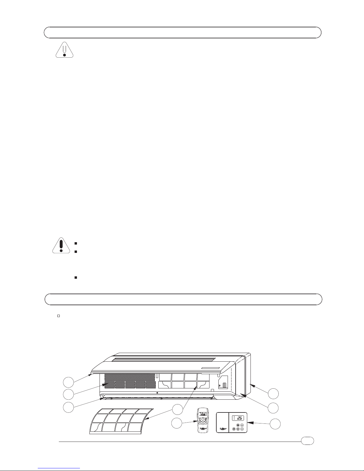
* Refer to dimensiona l drawings f or l ocation of liquid solution piping, c ondensate drain,
* Check e lectrical s ervice p rovided by utility f or the s ite t o be s ure t he electrical
service c apacity c an handle the load i mposed by this u nit.
and electrical c onnections before s etting in p lace.
* This a ir conditioner must b e p roperly i nstalled in accordance with t he Installation M anual.
READ ALL S AFETY I NFORMATION BEFORE INSTALLATION:
* Installations m ust be p erformed by a q ualified technician.
* Check a ll local c odes a nd ordinances that c ould a ffect installation o f this u nit.
* Refer to rating plate on e ach unit f or the c orrect v oltage, f requency a nd amperes.
* Be sure t hat t he p ower s upply c orresponds to t he s pecified r ating i n t he nameplate.
* Do n ot u se e xtension cords. I n t he c ase e xtended c ables a re n eeded, install longer power
cord from terminal block.
* Before c arryi ng o ut installation, p ut on p roper i ndividual p rotection d evice(s).
Sharp e dge s and coil s urfaces a re a p otential injury hazard. A void c ontact
Moving m achinery a nd e lectrical p ower is hazardous. It m ay c ause s evere
injury or d eath. T urn o ff a nd d isconnect t he power d uring installation a nd
THIS PRODUCT MUST BE P ROPERLY G ROUNDED.
with t hem.
repair bef ore a ny s ervices are a ttempted on t he u nit.
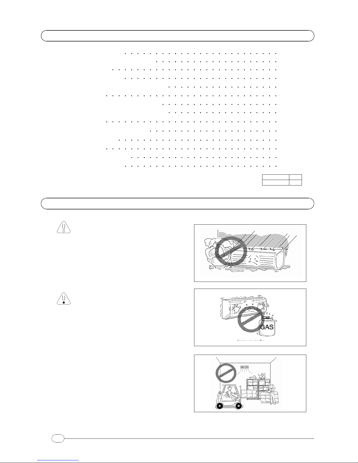
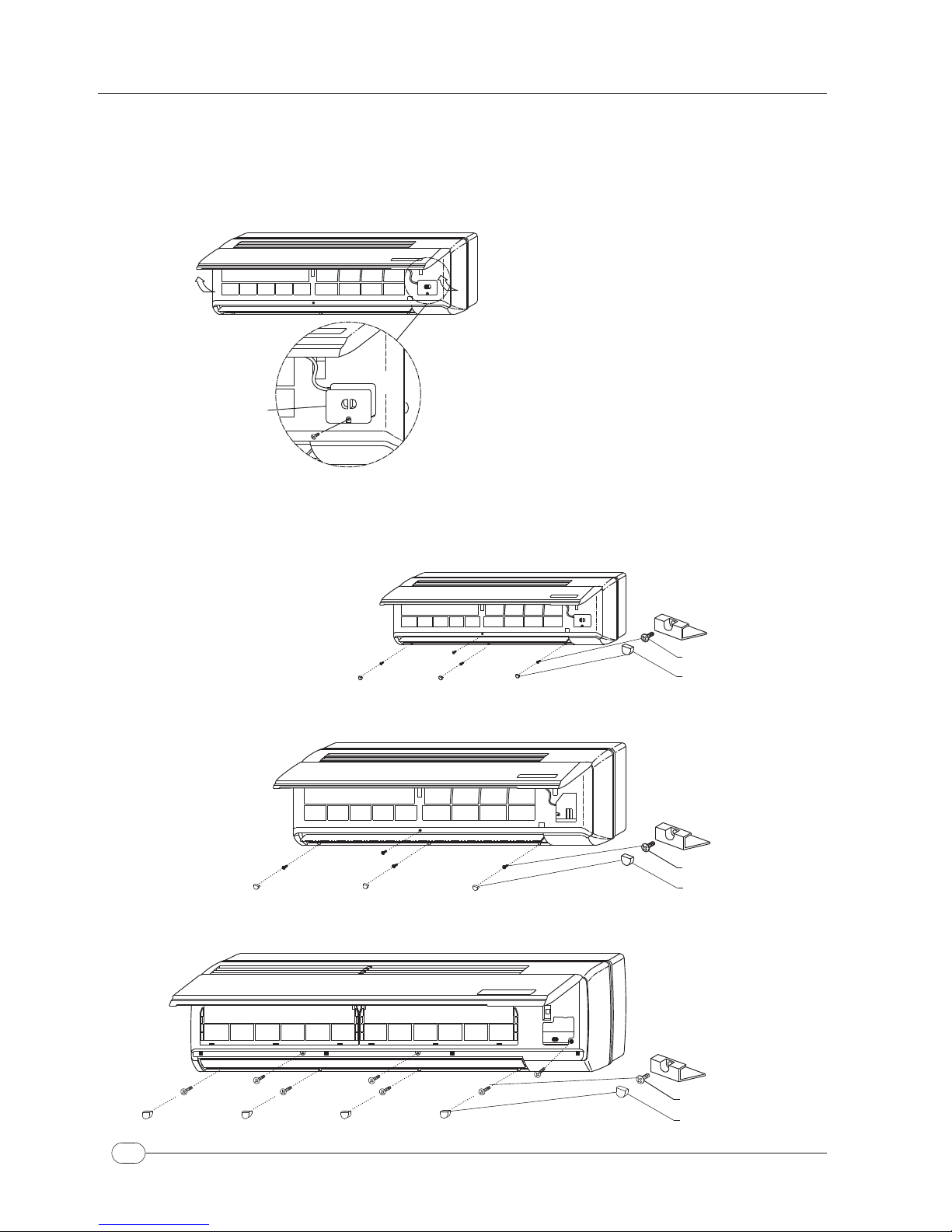
1. D eco P anel
2. E vaporator C oil
3. H orizontal L ouver
8. T hermostat C ontroller
6. B ase P an
7. F rame G rille
5. R emote Control U nit
4. Air Filters
PREP ARATIONS B EFORE INSTALLATION
MAIN C OMPONENTS
FAN C OIL U NIT
* The a ppliance s hall b e installed in a ccordance w ith n ational and local w iring r egulations.
* This a ppliance is n ot i ntended f or u se by persons not experienced or knowledgeable
on this product
.
* Means for disconnection must be inc orporated in the fixed wiring i n accordance
with t he w iring rules and local codes.
2
1
2
34
6
5
7
2. I s air i nlet o r o utlet o bstructed?
1. I s the set temperature
3. A re filters dirty?
2. I n s ufficient C ooling
or H eating.
4. I s t he re a ny o ther h eat s ource
in the r oom?
2. R emove o bjects that o bstruct
1. R eset s uitable s et tempe-
5. Is t he re a la rge n umber o f
people i n t he r oom?
suitable? rature.
the air inlet a nd o utlet.
3. C lean filters a nd o ther p art.
3. W ireless r emote
controller is not
functioning.
3. A re t he b atteries low ?
1. I s t he remote c ontrol u nit o ut
2. A re ther e any o bstructions b et-
of e ffective d istance f rom the
thermostat?
ween t he r emote controller
and thermostat ?
1. Use t he remote c ontroller w ithi n
2. R emove or c lean t he o bstruction.
sufficient d istance o f the thermostat.
3. R eplace w ith n ew b atteries.
TROUBLE S HOOTING G UIDE
If the unit appears to be malfunctioning, check the f ollowing p oints before calling
for service.
PROBLEM PROBLEM C AUSE REMEDY
2. I s t he w iring c onnection l oose?
1. H as p ower b een s hut down
3. Is t he p ower protection
1. A ir c onditioner
doesn't o perate.
in operation?
2. T ighten t he c onnection.
1. W ait for p ower to resume.
3. R eset t he power button.
4. R eplace f use
or r eset the
circuit breaker.
4. I s the fuse b lown o r circuit
breaker open?
or h as power f ailure o ccurred?
Problems that needs qualified personnel assistance.
PROBLEM PROBLEM C AUSE REMEDY
3. T erminal loose.
1. F aulty transformer, r elay a nd/or 1. Air c onditioner
doesn't run. 2. C heck the c ause o f malfunctioning
1. R eplace faulty c omponents.
3. C heck a nd retighten a ny loose
fan m otor c apacitor.
2. C ontrol b oard n ot f unctioning. and r eplace control b oard
if n ecessary.
4. I s w ater v alve or circulator
functioning ? terminals.
4. C heck to s ee if w ater v alve o r
circulator is opening o r actuating.
21
AUTO
LOW
MED
HIGH
8
CANCEL
SLEEP SEND
SWEEP MODE
HIGH COOL
TM
Multi
aqua
TM
Multi
aqua

5. R EMOTE C ONTROL - U sing this m akes it p ossible t o set a ll o perating
the p rogramming o perations easier.
parameters o f the u nit. These p arameters a re s hown i n the LCD d isplay t o m ake
4. A IR FILTERS - T o trap d irt a nd dust c oming from t he air.
8. THERMOSTAT C ONTROLLER - Thes e t hermostat a re mercury f ree and r equire
6. B ASE PAN - T he base o f the w hole unit.
7. F RAME GRILLE - T his component is attached to t he deco p anel a nd a ir f ilters
no b attery. A ll s et p oints a re kept b y n on-volatile memory.
Use a s the cover o f u nit.
1. D ECO PANEL - the air int ake is v ia the s lots. W hen r aising the panel, o ne has
2. E VAPORATOR C OIL - T his is m ade of a c opper t ube w ith t urbel ented type
3. H ORIZONTAL L OUVER - Used t o deflect the air from the unit. This is operated with
access to the a ir f ilters a nd the o the r int ernal parts.
aluminum fins.
the s tep m otor.
Select the location of fan coil unit with following consideration:
1. The front of air inlet a nd o utlet shall b e free from a ny obstruction.
2. The wall w here u nit is t o be mounted should be strong e nough to bear the
3. Ensure the clearance o n every s ide of fan coil unit t o conform to figure 1.
INSTALLATION PROCEDURE
weight a nd n ot to produce n oise.
The o utlet a ir s hould flow o ut f reely.
4. F rom floor, the h eight s hould b e more than e ye level.
Avoid installing the unit in direct sunlight.
Description o f the c omponents
MAIN C OMPONENTS
3
AIR F LOW D IRECTION
MAINTENANCE & SERVICING S PACE
Dimensions a re in m illimeter.
150.0
150.0
HIGHE R T HAN EYE LEVEL HIGHE R T HAN E YE LEVEL
FLOOR L EVEL
FIGURE 1
150.0
150.0
20
immediately after the unit is t urned ON o r OFF. This i s the
A soft, s wishing n oise can be heard d uring o peration o r
HEAR A H ISSING SOUND DURING O PERATION.
sound o f circulating cooling/heat agent. I t m ay a lso b e a ir
OPERATION T IPS
The following e vents m ay occur d uring n ormal o peration.
UNIT D OES NOT OPERATE I MMEDIATELY.
If y ou r estart t he fan coil w ithin 3 minutes o f
turning it off or c hange the m during operation, a protective
time d elay d evice w ill w ork to shut off t he unit f or 3 m inutes.
carpet, f urniture o r s moke may b e emitted from t he unit.
Odors p resent in the room, s uch a s t hose from the
A P ECULIAR S MELL COMING F ROM THE U NIT.
trapped i n the piping loop.
* Dirty and c logged f ilters r educe the c ooling efficiency of the u nit. I t is recommended
to c lean t he filters o nce every 2 weeks.
1. Open t he deco p anel by g rasping the rounded g rooves and pulling
towards you.
2. Hold the tabs o f air f ilter a nd r aise it slightly, then pull filter downwards.
3. Clean the air f ilters with vacuum c leaner o r w ash with w ater t hen dry.
4. Do not u se b enzene, t hinner, p olishing chemical o r s imilar s olvents fo r
cleaning. These m ay c ause the s urfaces to crack or deform.
5. Install t he a ir filter v ise versa o f removing proc edure. The correct
filter s ide i s indicated b y words " FRONT" m arked o n the f ilter.
1. External w eekly cleaning is to be done w ith a dry cloth soaked with
fresh water and mild soap, avoid using any other type of detergent.
2. The Frame grille with deco p anel can be removed. Clean with warm
water n ot over 120° F and w ipe w ith dry cloth.
3. Do n ot u se a c hemically treated cloth or duster to clean the unit.
4. Do not use benzene, thinner, p olishing chemical o r similar s o lvents f or
cleaning. T hese m ay cause surface d iscoloration, cracks
CARE & M AINTENANCE
or d eformation.
The " FRONT" side should b e f acing y ou.
TM
Multi
aqua
*LOCATION FOR FAN COIL UNIT
*CLEANING THE FAN COIL UNIT
*CLEANING AIR FILTERS

INSTALLATION P ROCEDURE
4
2. R eferring to the figure b elow, m ark t he l ocation for the wall plugs and the h ole for the pipings.
on the wall. M ake s ure the alignment is h orizontal. U se a plumb line, i f a vailable.
1. After a s uitable place for installation has b een s elected, p lace t he m ounting p late h orizontally
PLAN DIMENSIONS FOR MOUNTING PLATE INSTALLATION
MHQWW-18-H-1-U
MODEL A CB ED F
ุ 2.25
HG JI
Dimensions a re i n inches.
MODEL
MHQWW-09-H-1-U
MHQWW-12-H-1-U
34.65
38.98
A
11.63
11.73
7.25
7.25
B C E
2.75
2.75
2.75
2.75
D
.875
.875
F
ุ2.0
ุ2.0
1.875
1.875
.875
.875
G H
1.625
1.625
I J
(Right, Backward P iping H ole)
(Left, Backward P iping H ole)
Outline o f the Fan Coil
JJ
Mounting
(Left, Backward P iping Hole) (Right, Backward Piping Hole)
46.06 12.50 5.50 5.05.0 1.50 1.625 1.50 1.625
MODEL A CB ED F HG JI
MHQWW-36-H-1-U ุ 2.75
56.75 14.0 5.86 4.508.87 1.25 1.75 1.25 1.75
(Left, Backward Piping H ole) (Right, Backward P iping Hole)
19
If y ou plan to leave the unit idle for a long time, perform the following:
1. Disconnect Power.
2. Ensure n o w ater is moving t hrough t he u nit.
1. C heck if the air f ilter i s installed a nd t he a ir o utlet is n ot b locked.
2. C onnect Power.
CARE & MAINTENANCE
* Sharp e dges a nd coil s urfaces are a p otential i njury hazard . A void c ontact
* Disconnect a nd l ock o ut t he power before making any repair or any services.
with t hese.
WARNING
3. Remove t he batteries from the r emote controller.
3. Replace t he remote c ontrol batteries.
The horizontal louver and air d eflectors o n t he air d elivery can be arranged
in two d irections:
* Horizontal l ouver to be oriented manually.
* Air d eflectors to be oriented manually.
ORIENT T HE AIR DEFLECTOR:
- Turn the air d eflector as indicated in the figure
- Both in Heating a nd C ooling mode. It is a dvisable
for the a ir f low n ot to hit p eople directly.
MOTORIZED HORIZONTAL L OUVER:
- Never orient t he motorized horizontal louver
manually. A ny m anual o peration on the louver
may c ause d amage in the s ystem a nd cause
malfunctioning.
ADJUSTING AIR FLOW DIRECTION
MHQWW-24-H-1-U
Dimensions a re i n inches.
Dimensions are in inches.
CC
A
GF
D E
B
I
H
B
I
H
ED
GF
C C
A
GF
D
B
I
H
E
Outline of the
Fan Coil Unit
Outline o f th e Fan C oil U nit
JJ
Mounting P late
Mounting
Plate
J
J
A
CC
*MOUNTING PLATE INSTALLATION
MAINTENANCE
CHECK BEFORE OPERATION

Back s ide o f t he unit
Note : L ay t he drain hose as s hown a bove
Lower
hook
Mounting plate
Detail o f A
Base pan Mounting
Water
Piping
Plate
Drain h ose
Electrical c able
Wall
6. D rill a p iping hole 7 0.0 mm d iameter h ole either from t he right or to the left
fan coil s ide and make sure that the hole is slightly slant downward.
5. S ecure the m ounting plate a nd check for stiffness.
3. Drill 6.4 mm diameter, 32.0 mm d epth on t he wall.
4. Insert the w all p lugs.
3. T ape the tubing, d rain hose, and connecting c able.
2. Insert the fan coil unit pipings and drain pipe through the hole.
4. F or the horizontal piping, make sure they are laid along the groove a t
the b ack of unit a nd s ecure the piping using p iping c lamp ( 2 pieces)
on t he base pan.
1. Route the fan coil tubing with drain hose to the hole. There are four p ossible tubing routes.
For the route 1, 2 and 4 c ut the p late to pass the pipe through it, remove sharp e dge left
before f ixing to mounting plate
5. S ecure t he unit to t he mounting p late.
32.00 mm
Drill diameter 6.4 mm. depth 32.0 mm h oles
7. I f t he wall is hollow please provide a sleeve f or t ube assembly to p rotect the
drain l ine, pipings and field connection.
ุ6.4
Secure m ounting plate a nd c heck the s tiffness.
Set w all-pipe a nd c apsDrill a piping hole with Drill from the outside
70.0mm d iameter
from fan coil side.
concrete drill or hole saw
(not supplied)
Out side
Machine
Drilling
Hole saw slant
Slightly
Wall
Fan coil
Wall
Wall
Cap
Wall pipe
Cut w ith s aw
INSTALLATION P ROCEDURE
TUBING R OUTE:
Mounting Plate
location
Long s crews
Wall P lug
START-UP N OTICE
5 18
1. Be sure that t here i s n o obstruction i n
2. Check that the filter is installed.
4. Check that g round w ire i s properly
3. Check that t he p ower supply
Air o utlet
the a ir o utlet a nd i ntake v ents.
connected.
is connected.
Air i n let Air inlet
Air outlet
Wall
Taping A
Mounting Plate
Down
2
Right Side
1
Left S ide
Back S ide
3
4
TM
Multi aqua
REMOTE C ONTROLLER OPERATION G UIDE
To cancel p ress button u ntil t imer s ymbol is blinking,t hen press button.
CANCEL
7. TIMER O N/OFF
To turn on/off the air conditoner in advance.
- Press button to s et t he timer.
- Press S END button t o c onfirm t he s etting.
- P ress button u ntil clock symbol is blinking.
6. CLOCK S ETTING
- P ress S END b utton t o confirm setting.
- P ress button t o s et the t ime.
To s et the cl ock o n t he R emote u nit.
- Press button u ntil timer s ymbol O n or
OFF i s blinking
Remark
*PIPING AND DRAINAGE OF FANCOIL UNIT

INSTALLATION P ROCEDURE
6
Tape
Drain
Hose
Coating
Saddle
Interconnecting
Wiring
Pipe
Coupling
Drain Hose
Saddle
Putty
OUTSIDE OF THE WALL
*FIELD PIPING CONNECTIONS
Water I n
INSULATION OF PIPES :
1. The pipe insulation should cover both INLET a nd OUTLET pipes as shown below.
2. Use t he insulation o f p olyethylene foam minimum of 6 mm. in t hickness.
Insulation
Water In
NO
Water In
Water Out
YES
Water O ut
Insulation
Water Out
9. C arefully seal any wall opening from w eather to avoid any ingress of water.
8. Ensure that t he drain hose h as n o t raps o r d ips to impede the w ater flow.
6. Connect t he p iping and make s ure that the seals a re fitted neatly.
7. C onnect the d rain h ose and t ape over t he connecting p arts.
PIPING:
The piping lines must be installed level in both horizontal
and v ertical plane.
MODEL
1/2" FLARE
WATER INLET WATERO UTLET
CONNECTION
MHQWW-09-H-1-U & MHQWW-12-H-1-U 1/2" FLARE
5/8" FLARE 5/8" FLARE
3/4" FLARE 3/4" FLARE
Dip
YES NO
1. Maximum inlet w ater t emperature...........................160° F
OPERATIONAL L IMITS:
2. Maximum o perating p ressure..................................11 bar
3. T he a ssembly s ite must b e c hosen in s uch a way t ha t the maximum a nd minimum
ambient t emperature limits T a a re respected 0°C < Ta < 45°C, R.H. < 85%.
CANCEL
SLEEP SEND
SWEEP MODE
HEAT/COOL
* Press b utton t o change the m ode of o peration i n t he following sequence.
2. Mode
17
FAN COOL DRY FAN COOL DRY HEAT AUTO
Cool o nly m ode Heat / Cool m ode
* Press b utton to s et the temperature.
3. TEMPERATURE S ETTING
4. FAN
* Press b utton to s et t he fan speed.
5. SLEEP
* Press b utton to activate the Sleep function which w ill raise up/reduce the s et
SLEEP
AUTO MED
LOW HIGH
temperature 1˚C f or C ool/Heat mode respectively.
*DESCRIPTIONS A ND FUNCTION OF REMOTE CONTROLLER
1POWER
CANCEL
3TEMP U P/DOWN
2MODE
SEND
4
7
5
FAN
SLEEP
6
CLOCK/TIMER
LED D ISPLAY
* Press to t urn ON/OFF the a ir c onditioner. W hen turned on, it will operate a ccording t o t he
last p rogram setting.
1. POWER ON/OFF
*FUNCTION
MHQWW-18-H-1-U & MHQWW-24-H-1-U
MHQWW-36-H-1-U
REMOTE C ONTROLLER O PERATION G UIDE
MODE
NO

*HOW T O REMOVE T HE FRAME GRILLE
1. O pen the front panel b y grasping the panel a t t he side rounded g roove a nd p ulling it
towards you.
2. U n screw the terminal c over and pull out
as s hown in t he illustration.
Terminal
Cover
3. Remove the 3 or 4 s crews c over (depended o n the model) a nd t he mounting s crews
of the frame grille (please refer to the illustration).
MODEL: MHQWW-18-H-1-U & M HQWW-24-H-1-U
MODEL: MHQWW-09-H-1-U & MHQWW-12-H-1-U
Screws
Screws Cover
- The r em ote control s ignal can be r eceived at the distance of up t o a bout 7 Meters.
- Be s ure that n o o bstructions between receiver a nd r emote controller.
- Point t he r emote c ontrol unit transmitter t owards t he air conditioner r eceiver
- To be able t o carry out a ny o peration or change o f the setting from the r emote
while t he setting is being stabilise.
control u nit a ir c onditioner must b e powered.
USE OF T HE REMOTE CONTROLLER
PREPARATION OF T HE REMOTE CONTROLLER
- Open t he b attery cover b y p ressing slightly in the direction
- Insert t wo 1 .5 Volt high performance alkaline batteries ( AAA),
being c areful n ot to i nvert the p olarity.
- Close the battery cover.
of arrow.
7
INSTALLATION PROCEDURE
MODEL: M HQWW-36-H-1-U
Screw
Screw C overs
Screws
Screws Cover
Press button to select the f an s peed in the following sequence.
LED a t will s how t he s tatus of the fan speed.
3. FAN
AUTO MED
LOW HIGH
Auto mode
The Speed will be a djusted according to the difference between the r oom a nd t he s et temp.
If the difference is 3 ˚C o r m ore, t he f an will run at HIGH speed.
If t he d ifference i s 2˚C or more, the fan will run a t MED s peed.
If t he difference i s 1˚C o r m ore, t he fan will r un a t L OW s peed.
Press or b utton f or setting temperature i n a r ange of 1 5-30˚C o r 5 8-88˚F.
4. Temperature s etting
7 segment d isplay w ill s how t he new s etting f or 5 s econds.
REMOTE C ONTROLLER O PERATION G UIDE
16
THERMOSTAT CONTROLLER OPERATION G UIDE
Cool m ode
Dry m ode
Fan m ode
Heat m ode
: 7 Segment w ill flash for 5 seconds.
: 7 S egment will flash for 5 seconds.
: 7 S egment w ill f lash for 5 seconds.
Auto mode : 7 S egment will f lash for 5 s econds.
The s ystem w ill automatically switch from Cool to Heat mode or vice v ersa.
• flashing for 5 s econds i f t he H ot Water Pipe version is ordered.

INSTALLATION P ROCEDURE
4. Set the horizontal louver to the c losed position, d etach h orizontal louver s tud o n left s ide
and push i nside ( please s ee i llustration).
When p erforming t his action, p lease do it gently to avoid d amaging t he louver.
2. P our a glass of w ater into the drain p an.
*CHECKING T HE DRAINAGE
3. Ensure t hat th e water f lows o ut f rom t he
Drain Pan
Hose
Drain
1. Turn off power to t he u nit.
8
drain hose o f f a n c oil unit.
2P f or the power and 1 P f or t he e arth terminal/ground.
Power outlet
3 P ole
Model Used
5A
Amp.
or C ircuit
Time d elay fuse
Breaker MHQWW-09-H-1-U, M HQWW-12-H-1-U, MHQWW-18-H-1-U
MHQWW-24-H-1-U & M HQWW-36-H-1-U
*WIRING CONNECTIONS
Connect t he unit to adequate p ower o utlet.
(Rating v oltage ± 1 0 during operation)
Adequate P ower Outlet
* Always refer to the wiring diagrams inside the unit.
* Check l ocal electrical c odes a nd a lso a ny s pecific w iring c odes.
* Be s ure to t urn off the m ain p ower s upply before open t he
frame grille for s ervicing.
7. P lug in the power supply c ord a t t he power outlet, ( See Page 10).
6. B e sure t hat all w iring c onnections c omply t o t he w iring diagram
5. Secure all field c able on t o control b ox w ith wire c lamp.
control b ox a nd s crew i t tightly.
4. C onnect the connecting c ables of t he power cord to the terminal block on the
2. O pen t he control box cover b y l oosening t he screw.
3. Loosen t he w ire clamp s crews
before covering the control box.
1. Remove t he f rame g rille.
5. Open the front p anel b y grasping the panel a t t he s ide rounded g roove and
6. Grasp t he l ower p art o f t he f rame g rille and p ull i t o ut.
pulling it towards y ou.
* Press to turn O N/OFF the air conditioner. When t urned on, it will operate according t o the
last program s etting.
1. POWER O N/OFF
DESCRIPTIONS A ND FUNCTION OF WIRED CONTROLLER
*FUNCTION
AUTO
LOW
MED
HIGH
4
4
3
1
2
For cool , heat, dry and auto functions
2. MODE
For other v ersion, this is a MODE b utton u sed t o select the operation m ode.
FAN COOL DRY FAN COOL DRY HEAT AUTO
Cool o nly mode Heat / C ool m ode
15
5
THERMOSTAT CONTROLLER OPERATION GUIDE
2. Return the terminal cover by fastening it's screw.
3. Close and p ush t he front panel into t he frame grille u ntil the "click" s ound is heard
MODEL: M HQWW-09-H-1-U, MHQWW-12-H-1-U, MHQWW-18-H-1-U
MODEL: MHQWW-36-H-1-U
PUSH 1
PUSH 3
PUSH 2
PUSH 4
PUSH
PUSH 2
PUSH 3
TM
Multi aqua
TM
Multi aqua
INSTALLATION PROCEDURE
TEMP. DOWN
TEMP. UP
FAN SPEED
POWER
MODE
LED T EMP.
DISPLAY
FAN S PEED
STATUS
& MHQWW-24-H-1-U
1

2. O pen t he water i nlet v alve a nd f lood t he c oil.
turn on the p ower and turn the unit on in cooling.
1. A fter c onnecting the water i nlet and outlet p ipes t o t he m ain w ater s upply l ines,
4. When no air bubbles appear, close the purging v alve (Clockwise)
When performing t his, take c are not to touch the
3. C heck a ll c onnections f or w ater leak, if n o leak is found , loosen (1 turn, c ounter
with a n open e nd w rench ( No.10), t hen p urge the trapped air i nside t he c oil.
clockwise) t he purging v alve b y using standard h ead s crew driver and s upport
5. O pen the water outlet valve.
* A IR PURGING
electrical parts.
1. I nstall the frame grille i n t he opposite o rder o f "HOW T O R EMOVE T HE FRAME GRILLE".
When t he frame g rille is r emoved a nd mounted a gain, t ake t he following a ctions:
Before fastening t he mounting s crews be s ure t o hook the t op i nside l ock of t he f rame grille.
* HOW T O INSTALL T HE FRAME GRILLE ON T HE FANCOIL UNIT
9
INSTALLATION P ROCEDURE
INSTALLATION PROCEDURE
Screw
Screw C overs
Open e nd wrench
(No.10)
screw D river
Standard head
OPEN
Base P an
Terminal Block
Control Box
Frame Grille
Control Box Cover
Wire clamp
MODEL: M HQWW-09-H-1-U, M HQWW-12-H-1-U, M HQWW-18-H-1-U
1 2 3 4
567
From W CV
twisting them t ogether.
Hold the two w ires s teady
the e nd of connecting wire.
Connect t he two w ires b y
There a re t hree e xtention w ires (A WG1 8 Blue, R ed a nd Y ellow color) c oming o ut f rom
from o ne h and a nd
Fig.1
Fig.2
until i t become t ighten.
Fig.4
rotate t h e wire connector
Strip the insulation 1 /2" from
figures.
Connect the two e xtention
wires in t o W ater Control
Valve as s hown o n the
Water c ontrol
valve e xtention
wires A WG18.
Basep an
unit
from top.
connector
connector to protect
Insert the w ire
Use the supplied wire
From f an coil
unit
Fig.3
the b ear e nd.
the fan coil terminal b lock for the w ater c ontrol v alve ( please refer to the w iring diagram).
Terminal
wires to controller
Connecting
Inter-connection
Read these instructions thoroughly b efore installing p roduct. Failure to follow these i nstructions
could damage the product or c ause a h azardous c ondition. C heck t he v oltage a nd current
* INSTALLATION
ratings to ensure that it is suitable f or your application. Installer must be a trained,
experienced s ervice technician. C heck product for proper o peration a fter i nstallation.
14
Extension w ires
Block
wires
* WIRE CONNECTION T O T HE T ERMINAL BLOCK
THERMOSTAT CONTROLLER INSTALLATION GUIDE
Mount the thermostat a pprox. 5 ft. ( 1.5m) a bove t he floor in a location t hat is free f rom d irect
sunlight, heat from a ppliances, h ot o r c old a ir f rom ducts, c oncealed pipes and c himneys,
* MOUNTING LOCATION
and d rafts o f d ead s pots behind d oors or in a corner. D o n ot m ount o n exterior w all, if
possible. F ailure to locate thermostat m ounting as indicated m ay r esult in poor temperature
control.
MHQWW-24-H-1-U & MHQWW-36-H-1-U
1/2”

WIRING D IAGRAM
13
Model: MHQWW-36-H-1-U
WIRE COLOURS
TERMINAL BLOCK LEGEND
LEGEND
:
:
FIELD W IRING
EARTH/GROUND
BLACK
BK
GREEN
BROWN
GR
BR
:
:
:
WH
YL:
:
RD
:
FACTORY
WHITE
YELLOW
RED
:
:
:
:
:
24V C OMMON
(C) 3
(24V) 2
:EARTH/GROUND
5
24V T RANSFORMER
::
TF
(L2) 6
(L1) 7
LIVE 2 (110V)
LIVE 1 (110V)
:
(24V) 1
:
24V WCV CONTROL
24V W CV CONTROL
CONNECTION
CONNECTION
CONNECTION
CONNECTION
CONNECTION
BLUE
BL:
WIRING
WIRING
COOL
HEAT
L(SEC)
C(SEC)
C(SEC)
COOL
HEAT
24V
COM
FAN L
FAN M
FAN H
LIVE2
LIVE1
NUETRAL
NUETRAL
INDOOR
FAN
MOTOR
LED3
FAN L
LED2
FAN M
LED1
FAN H
LED5
RUN
LED4
PWR
BK
GR
YL
WH
6 7
NC TO C OIL
NC T O COIL
HEATING
COOLING
L2 L1
5
208V-230V,
1Ph,50/60Hz
BK
BR
GR+YL
YL
RD
BL
TF
INDOOR U NIT
COOL
HEAT
FAN L
FAN M
FAM H
SWING
MOTOR
C (24Vac)
L (24Vac)
BK
BK
CANCEL
SLEEP SEND
SWEEP MODE
HEATING/COOLING
NC TO C OIL
BK
BR
1 2 3 4
YL
RD
BL
YL
YL
GR+YL
REMOTE UNIT
CONTROLLER
FAN
CAP.
THERMOSTAT
CONTROLLER
(OPTIONAL)
10
CAUTION
Damage to cooling s ystem may occur. Disconnect power f rom e quipment at the main breaker/
fuse block w hile installing the thermostat.
1.1. Cut t he plastic a nd open
hole w ith p liers.
Installation B (wires o n wall)
1.2. Use c able 0 .5-1sq.mm
connect t he wires into
1.2. Install back plate i nto
the wall w ith s crews.
terminals.
2.Install t he front case, c arefully inspect
wiring a s p er d iagram before
mounting thermostat.
3. Tighten t he screw f irmly.
1. L ift a nd o pen top s ide using s crew d river.
1.1. Use c able 0 .5-1sq.mm c o nnect the
wires into t erminals.
Installation A (wires t hough w all)
1.2. Installing b ack plate into t he wall
with s crews.
THERMOSTAT CONTROLLER IN STALLATION GUIDE
(COOL)
(HEAT)
NOTES
1. 2 30V - 24Vac T RANSFORMER
2. W IRELESS REMOTE INCLUDES A W ALL M OUNTING BRACKET ( OPTIONAL)
3. J UMPER MUST BE FIELD I NSTALLED FOR 2-PIPE H EAT/COOL OPERATION
4. 4-PIPE W IRING AND C ONFIGURATION
5. 2 -PIPE W IRING AND V ALVE C ONFIGURATION
6. T HERMOSTAT C ONTROLLER UNIT
7. T HE FIELD W IRING C ONDUCTOR O F HIGH A ND L OW V OLTAGE C IRCUIT S HALL B E S EPERATELY
FIXED FIRMLY BY E ACH CLAMP.
8. A LL W IRING S HALL B E DONE A CCORDING TO T HE NATIONAL A ND LOCAL C ODE R EQUIREMENTS.
9. A LINE OF SIGHT SERVICE D ISCONNECT M UST BE PROVIDED A S A M EANS T O T URN O FF POWER
FOR SERVICING.
NOTE 2
NOTE 1
NOTE 3
NOTE 5
NOTE 6
NOTE 4
(60Hz)
(50Hz)
RD
GY
OR
P/N: PP170605

MODEL : MHQWW-09-H-1-U & M HQWW-12-H-1-U
WIRING D IAGRAM
Model: MHQWW-18-H-1-U & MHQWW-24-H-1-U
COOL
HEAT
L ( SEC)
C ( SEC)
C ( SEC)
COOL
HEAT
24V
COM
FAN L
FAN M
FAN H
LIVE 2
LIVE 1
NUETRAL
NUETRAL
INDOOR
FAN
MOTOR
LED3
FAN L
LED2
FAN M
LED1
FAN H
LED5
RUN
LED4
PWR
BK
GR
YL
WH
6 7
NC T O C OIL
NC T O C OIL
HEATING
COOLING
L2 L1
5
208V-230V,
1Ph,50/60Hz
BK
BR
GR+YL
YL
RD
BL
TF
INDOOR U NIT
COOL
HEAT
FAN L
FAN M
FAM H
SWING
MOTOR
C (24Vac)
L (24Vac)
CANCEL
SLEEP SEND
SWEEP MODE
HEATING/COOLING
NC T O C OIL
1 2 3 4
YL
RD
BL
YL
YL
THERMOSTAT
REMOTE U NIT
CONTROLLER
CONTROLLER
BR
RD
LEGEND
:
:
FIELD WIRING
EARTH/GROUND
FACTORY
:
WIRING
WIRING
(OPTIONAL)
LEGEND
:
:
FIELD W IRING
EARTH/GROUND
FACTORY
:
WIRING
WIRING
COOL
HEAT
L(SEC)
C(SEC)
C(SEC)
COOL
HEAT
24V
COM
FAN L
FAN M
FAN H
LIVE 2
LIVE 1
NUETRAL
NUETRAL
RD
FAN CAP.
INDOOR
FAN
MOTOR
LED3
FAN L
LED2
FAN M
LED1
FAN H
LED5
RUN
LED4
PWR
BK
GR
YL
WH
6 7
NC TO COIL
NC T O COIL
HEATING
COOLING
L2 L1
5
208V-230V,
1Ph,50/60Hz
BK
BR
GR+YL
YL
RD
BL
TF
BR
INDOOR U NIT
COOL
HEAT
FAN L
FAN M
FAM H
SWING
MOTOR
C (24Vac)
L (24Vac)
CANCEL
SLEEP SEND
SWEEP MODE
HEATING/COOLING
NC T O COIL
1 2 3 4
YL
RD
BL
YL
YL
GR+YL
REMOTE UNIT
CONTROLLER
THERMOSTAT
CONTROLLER
(OPTIONAL)
11
WIRING D IAGRAM
12
WIRE COLOURS
TERMINAL BLOCK LEGEND
BLACK
BK
GREEN
BROWN
GR
BR
:
:
:
WH
YL:
:
RD
:
WHITE
YELLOW
RED
:
:
:
:
24V C OMMON
(C) 3
(24V) 2
:EARTH/GROUND
5
24V T RANSFORMER
::
TF
(L2) 6
(L1) 7
LIVE 2 ( 110V)
LIVE 1 ( 110V)
:
(24V) 1
:
24V W CV CONTROL
24V WCV CONTROL
CONNECTION
CONNECTION
CONNECTION
CONNECTION
CONNECTION
BLUE
BL:
(COOL)
(HEAT)
WIRE C OLOURS
TERMINAL B LOCK LEGEND
BLACK
BK
GREEN
BROWN
GR
BR
:
:
:
WH
YL :
:
RD :
WHITE
YELLOW
RED
:
:
:
:
24V C OMMON
(C) 3
(24V) 2
:EARTH/GROUND
5
24V T RANSFORMER
::
TF
(L2) 6
(L1) 7
LIVE 2 ( 110V)
LIVE 1 ( 110V)
:
(24V) 1
:
24V W CV CONTROL
24V W CV CONTROL
CONNECTION
CONNECTION
CONNECTION
CONNECTION
CONNECTION
BLUE
BL :
(COOL)
(HEAT)
NOTE 2
NOTES
1. 2 30V - 24Vac T RANSFORMER
2. W IRELESS R EMOTE INCLUDES A WALL MOUNTING BRACKET ( OPTIONAL)
3. J UMPER MUST BE FIELD INSTALLED FOR 2 -PIPE H EAT/COOL OPERATION
4. 4 -PIPE W IRING A ND CONFIGURATION
5. 2 -PIPE W IRING AND V ALVE C ONFIGURATION
6. T HERMOSTAT CONTROLLER UNIT
7. T HE FIELD W IRING C ONDUCTOR OF HIGH AND LOW V OLTAGE C IRCUIT S HALL B E S EPERATELY
FIXED F IRMLY BY E ACH CLAMP.
8. A LL WIRING SHALL B E DONE ACCORDING TO THE NATIONAL AND L OCAL C ODE REQUIREMENTS.
9. A L INE O F SIGHT SERVICE D ISCONNECT M UST B E PROVIDED AS A M EANS T O TURN OFF P OWER
FOR S ERVICING.
NOTE 1
NOTE 3
NOTE 5
NOTE 4
NOTE 6
NOTES
1. 2 30V - 24Vac T RANSFORMER
2. W IRELESS R EMOTE INCLUDES A WA LL MOUNTING B RACKET ( OPTIONAL)
3. J UMPER MUST B E FIELD I NSTALLED F OR 2-PIPE H EAT/COOL OPERATION
4. 4 -PIPE W IRING A ND CONFIGURATION
5. 2 -PIPE W IRING AND V ALVE C ONFIGURATION
6. T H ERMOSTAT CONTROLLER U NIT
7. T HE FIELD W IRING CONDUCTOR O F H IGH A ND L OW VOLTAGE C IRCUIT SHALL BE S EPERATELY
FIXED F IRMLY B Y E ACH C LAMP.
8. A LL WIRING S HALL BE DON E ACC ORDING TO THE NATIONAL A ND LOCAL C ODE REQUIREMENTS.
9. A L INE O F S IGHT S ERVICE D ISCONNECT MUST BE PROVIDED AS A M EANS TO TURN O FF P OWER
FOR S ERVICING.
NOTE 2
NOTE 1
NOTE 3
NOTE 5
NOTE 6
NOTE 4
BK
BK
BK
BR
BK
BK
BK
BR
P/N: PP170207 P/N: PP170508

WIRING D IAGRAM
13
Model: MHQWW-36-H-1-U
WIRE COLOURS
TERMINAL BLOCK LEGEND
LEGEND
:
:
FIELD W IRING
EARTH/GROUND
BLACK
BK
GREEN
BROWN
GR
BR
:
:
:
WH
YL:
:
RD
:
FACTORY
WHITE
YELLOW
RED
:
:
:
:
:
24V C OMMON
(C) 3
(24V) 2
:EARTH/GROUND
5
24V T RANSFORMER
::
TF
(L2) 6
(L1) 7
LIVE 2 (110V)
LIVE 1 (110V)
:
(24V) 1
:
24V WCV CONTROL
24V W CV CONTROL
CONNECTION
CONNECTION
CONNECTION
CONNECTION
CONNECTION
BLUE
BL:
WIRING
WIRING
COOL
HEAT
L(SEC)
C(SEC)
C(SEC)
COOL
HEAT
24V
COM
FAN L
FAN M
FAN H
LIVE2
LIVE1
NUETRAL
NUETRAL
INDOOR
FAN
MOTOR
LED3
FAN L
LED2
FAN M
LED1
FAN H
LED5
RUN
LED4
PWR
BK
GR
YL
WH
6 7
NC TO C OIL
NC T O COIL
HEATING
COOLING
L2 L1
5
208V-230V,
1Ph,50/60Hz
BK
BR
GR+YL
YL
RD
BL
TF
INDOOR U NIT
COOL
HEAT
FAN L
FAN M
FAM H
SWING
MOTOR
C (24Vac)
L (24Vac)
BK
BK
CANCEL
SLEEP SEND
SWEEP MODE
HEATING/COOLING
NC TO C OIL
BK
BR
1 2 3 4
YL
RD
BL
YL
YL
GR+YL
REMOTE UNIT
CONTROLLER
FAN
CAP.
THERMOSTAT
CONTROLLER
(OPTIONAL)
10
CAUTION
Damage to cooling s ystem may occur. Disconnect power f rom e quipment at the main breaker/
fuse block w hile installing the thermostat.
1.1. Cut t he plastic a nd open
hole w ith p liers.
Installation B (wires o n wall)
1.2. Use c able 0 .5-1sq.mm
connect t he wires into
1.2. Install back plate i nto
the wall w ith s crews.
terminals.
2.Install t he front case, c arefully inspect
wiring a s p er d iagram before
mounting thermostat.
3. Tighten t he screw f irmly.
1. L ift a nd o pen top s ide using s crew d river.
1.1. Use c able 0 .5-1sq.mm c o nnect the
wires into t erminals.
Installation A (wires t hough w all)
1.2. Installing b ack plate into t he wall
with s crews.
THERMOSTAT CONTROLLER IN STALLATION GUIDE
(COOL)
(HEAT)
NOTES
1. 2 30V - 24Vac T RANSFORMER
2. W IRELESS REMOTE INCLUDES A W ALL M OUNTING BRACKET ( OPTIONAL)
3. J UMPER MUST BE FIELD I NSTALLED FOR 2-PIPE H EAT/COOL OPERATION
4. 4-PIPE W IRING AND C ONFIGURATION
5. 2 -PIPE W IRING AND V ALVE C ONFIGURATION
6. T HERMOSTAT C ONTROLLER UNIT
7. T HE FIELD W IRING C ONDUCTOR O F HIGH A ND L OW V OLTAGE C IRCUIT S HALL B E S EPERATELY
FIXED FIRMLY BY E ACH CLAMP.
8. A LL W IRING S HALL B E DONE A CCORDING TO T HE NATIONAL A ND LOCAL C ODE R EQUIREMENTS.
9. A LINE OF SIGHT SERVICE D ISCONNECT M UST BE PROVIDED A S A M EANS T O T URN O FF POWER
FOR SERVICING.
NOTE 2
NOTE 1
NOTE 3
NOTE 5
NOTE 6
NOTE 4
(60Hz)
(50Hz)
RD
GY
OR
P/N: PP170605

2. O pen t he water i nlet v alve a nd f lood t he c oil.
turn on the p ower and turn the unit on in cooling.
1. A fter c onnecting the water i nlet and outlet p ipes t o t he m ain w ater s upply l ines,
4. When no air bubbles appear, close the purging v alve (Clockwise)
When performing t his, take c are not to touch the
3. C heck a ll c onnections f or w ater leak, if n o leak is found , loosen (1 turn, c ounter
with a n open e nd w rench ( No.10), t hen p urge the trapped air i nside t he c oil.
clockwise) t he purging v alve b y using standard h ead s crew driver and s upport
5. O pen the water outlet valve.
* A IR PURGING
electrical parts.
1. I nstall the frame grille i n t he opposite o rder o f "HOW T O R EMOVE T HE FRAME GRILLE".
When t he frame g rille is r emoved a nd mounted a gain, t ake t he following a ctions:
Before fastening t he mounting s crews be s ure t o hook the t op i nside l ock of t he f rame grille.
* HOW T O INSTALL T HE FRAME GRILLE ON T HE FANCOIL UNIT
9
INSTALLATION P ROCEDURE
INSTALLATION PROCEDURE
Screw
Screw C overs
Open e nd wrench
(No.10)
screw D river
Standard head
OPEN
Base P an
Terminal Block
Control Box
Frame Grille
Control Box Cover
Wire clamp
MODEL: M HQWW-09-H-1-U, M HQWW-12-H-1-U, M HQWW-18-H-1-U
1 2 3 4
567
From W CV
twisting them t ogether.
Hold the two w ires s teady
the e nd of connecting wire.
Connect t he two w ires b y
There a re t hree e xtention w ires (A WG1 8 Blue, R ed a nd Y ellow color) c oming o ut f rom
from o ne h and a nd
Fig.1
Fig.2
until i t become t ighten.
Fig.4
rotate t h e wire connector
Strip the insulation 1 /2" from
figures.
Connect the two e xtention
wires in t o W ater Control
Valve as s hown o n the
Water c ontrol
valve e xtention
wires A WG18.
Basep an
unit
from top.
connector
connector to protect
Insert the w ire
Use the supplied wire
From f an coil
unit
Fig.3
the b ear e nd.
the fan coil terminal b lock for the w ater c ontrol v alve ( please refer to the w iring diagram).
Terminal
wires to controller
Connecting
Inter-connection
Read these instructions thoroughly b efore installing p roduct. Failure to follow these i nstructions
could damage the product or c ause a h azardous c ondition. C heck t he v oltage a nd current
* INSTALLATION
ratings to ensure that it is suitable f or your application. Installer must be a trained,
experienced s ervice technician. C heck product for proper o peration a fter i nstallation.
14
Extension w ires
Block
wires
* WIRE CONNECTION T O T HE T ERMINAL BLOCK
THERMOSTAT CONTROLLER INSTALLATION GUIDE
Mount the thermostat a pprox. 5 ft. ( 1.5m) a bove t he floor in a location t hat is free f rom d irect
sunlight, heat from a ppliances, h ot o r c old a ir f rom ducts, c oncealed pipes and c himneys,
* MOUNTING LOCATION
and d rafts o f d ead s pots behind d oors or in a corner. D o n ot m ount o n exterior w all, if
possible. F ailure to locate thermostat m ounting as indicated m ay r esult in poor temperature
control.
MHQWW-24-H-1-U & MHQWW-36-H-1-U
1/2”

INSTALLATION P ROCEDURE
4. Set the horizontal louver to the c losed position, d etach h orizontal louver s tud o n left s ide
and push i nside ( please s ee i llustration).
When p erforming t his action, p lease do it gently to avoid d amaging t he louver.
2. P our a glass of w ater into the drain p an.
*CHECKING T HE DRAINAGE
3. Ensure t hat th e water f lows o ut f rom t he
Drain Pan
Hose
Drain
1. Turn off power to t he u nit.
8
drain hose o f f a n c oil unit.
2P f or the power and 1 P f or t he e arth terminal/ground.
Power outlet
3 P ole
Model Used
5A
Amp.
or C ircuit
Time d elay fuse
Breaker MHQWW-09-H-1-U, M HQWW-12-H-1-U, MHQWW-18-H-1-U
MHQWW-24-H-1-U & M HQWW-36-H-1-U
*WIRING CONNECTIONS
Connect t he unit to adequate p ower o utlet.
(Rating v oltage ± 1 0 during operation)
Adequate P ower Outlet
* Always refer to the wiring diagrams inside the unit.
* Check l ocal electrical c odes a nd a lso a ny s pecific w iring c odes.
* Be s ure to t urn off the m ain p ower s upply before open t he
frame grille for s ervicing.
7. P lug in the power supply c ord a t t he power outlet, ( See Page 10).
6. B e sure t hat all w iring c onnections c omply t o t he w iring diagram
5. Secure all field c able on t o control b ox w ith wire c lamp.
control b ox a nd s crew i t tightly.
4. C onnect the connecting c ables of t he power cord to the terminal block on the
2. O pen t he control box cover b y l oosening t he screw.
3. Loosen t he w ire clamp s crews
before covering the control box.
1. Remove t he f rame g rille.
5. Open the front p anel b y grasping the panel a t t he s ide rounded g roove and
6. Grasp t he l ower p art o f t he f rame g rille and p ull i t o ut.
pulling it towards y ou.
* Press to turn O N/OFF the air conditioner. When t urned on, it will operate according t o the
last program s etting.
1. POWER O N/OFF
DESCRIPTIONS A ND FUNCTION OF WIRED CONTROLLER
*FUNCTION
AUTO
LOW
MED
HIGH
4
4
3
1
2
For cool , heat, dry and auto functions
2. MODE
For other v ersion, this is a MODE b utton u sed t o select the operation m ode.
FAN COOL DRY FAN COOL DRY HEAT AUTO
Cool o nly mode Heat / C ool m ode
15
5
THERMOSTAT CONTROLLER OPERATION GUIDE
2. Return the terminal cover by fastening it's screw.
3. Close and p ush t he front panel into t he frame grille u ntil the "click" s ound is heard
MODEL: M HQWW-09-H-1-U, MHQWW-12-H-1-U, MHQWW-18-H-1-U
MODEL: MHQWW-36-H-1-U
PUSH 1
PUSH 3
PUSH 2
PUSH 4
PUSH
PUSH 2
PUSH 3
TM
Multi aqua
TM
Multi aqua
INSTALLATION PROCEDURE
TEMP. DOWN
TEMP. UP
FAN SPEED
POWER
MODE
LED T EMP.
DISPLAY
FAN S PEED
STATUS
& MHQWW-24-H-1-U
1

*HOW T O REMOVE T HE FRAME GRILLE
1. O pen the front panel b y grasping the panel a t t he side rounded g roove a nd p ulling it
towards you.
2. U n screw the terminal c over and pull out
as s hown in t he illustration.
Terminal
Cover
3. Remove the 3 or 4 s crews c over (depended o n the model) a nd t he mounting s crews
of the frame grille (please refer to the illustration).
MODEL: MHQWW-18-H-1-U & M HQWW-24-H-1-U
MODEL: MHQWW-09-H-1-U & MHQWW-12-H-1-U
Screws
Screws Cover
- The r em ote control s ignal can be r eceived at the distance of up t o a bout 7 Meters.
- Be s ure that n o o bstructions between receiver a nd r emote controller.
- Point t he r emote c ontrol unit transmitter t owards t he air conditioner r eceiver
- To be able t o carry out a ny o peration or change o f the setting from the r emote
while t he setting is being stabilise.
control u nit a ir c onditioner must b e powered.
USE OF T HE REMOTE CONTROLLER
PREPARATION OF T HE REMOTE CONTROLLER
- Open t he b attery cover b y p ressing slightly in the direction
- Insert t wo 1 .5 Volt high performance alkaline batteries ( AAA),
being c areful n ot to i nvert the p olarity.
- Close the battery cover.
of arrow.
7
INSTALLATION PROCEDURE
MODEL: M HQWW-36-H-1-U
Screw
Screw C overs
Screws
Screws Cover
Press button to select the f an s peed in the following sequence.
LED a t will s how t he s tatus of the fan speed.
3. FAN
AUTO MED
LOW HIGH
Auto mode
The Speed will be a djusted according to the difference between the r oom a nd t he s et temp.
If the difference is 3 ˚C o r m ore, t he f an will run at HIGH speed.
If t he d ifference i s 2˚C or more, the fan will run a t MED s peed.
If t he difference i s 1˚C o r m ore, t he fan will r un a t L OW s peed.
Press or b utton f or setting temperature i n a r ange of 1 5-30˚C o r 5 8-88˚F.
4. Temperature s etting
7 segment d isplay w ill s how t he new s etting f or 5 s econds.
REMOTE C ONTROLLER O PERATION G UIDE
16
THERMOSTAT CONTROLLER OPERATION G UIDE
Cool m ode
Dry m ode
Fan m ode
Heat m ode
: 7 Segment w ill flash for 5 seconds.
: 7 S egment will flash for 5 seconds.
: 7 S egment w ill f lash for 5 seconds.
Auto mode : 7 S egment will f lash for 5 s econds.
The s ystem w ill automatically switch from Cool to Heat mode or vice v ersa.
• flashing for 5 s econds i f t he H ot Water Pipe version is ordered.

INSTALLATION P ROCEDURE
6
Tape
Drain
Hose
Coating
Saddle
Interconnecting
Wiring
Pipe
Coupling
Drain Hose
Saddle
Putty
OUTSIDE OF THE WALL
*FIELD PIPING CONNECTIONS
Water I n
INSULATION OF PIPES :
1. The pipe insulation should cover both INLET a nd OUTLET pipes as shown below.
2. Use t he insulation o f p olyethylene foam minimum of 6 mm. in t hickness.
Insulation
Water In
NO
Water In
Water Out
YES
Water O ut
Insulation
Water Out
9. C arefully seal any wall opening from w eather to avoid any ingress of water.
8. Ensure that t he drain hose h as n o t raps o r d ips to impede the w ater flow.
6. Connect t he p iping and make s ure that the seals a re fitted neatly.
7. C onnect the d rain h ose and t ape over t he connecting p arts.
PIPING:
The piping lines must be installed level in both horizontal
and v ertical plane.
MODEL
1/2" FLARE
WATER INLET WATERO UTLET
CONNECTION
MHQWW-09-H-1-U & MHQWW-12-H-1-U 1/2" FLARE
5/8" FLARE 5/8" FLARE
3/4" FLARE 3/4" FLARE
Dip
YES NO
1. Maximum inlet w ater t emperature...........................160° F
OPERATIONAL L IMITS:
2. Maximum o perating p ressure..................................11 bar
3. T he a ssembly s ite must b e c hosen in s uch a way t ha t the maximum a nd minimum
ambient t emperature limits T a a re respected 0°C < Ta < 45°C, R.H. < 85%.
CANCEL
SLEEP SEND
SWEEP MODE
HEAT/COOL
* Press b utton t o change the m ode of o peration i n t he following sequence.
2. Mode
17
FAN COOL DRY FAN COOL DRY HEAT AUTO
Cool o nly m ode Heat / Cool m ode
* Press b utton to s et the temperature.
3. TEMPERATURE S ETTING
4. FAN
* Press b utton to s et t he fan speed.
5. SLEEP
* Press b utton to activate the Sleep function which w ill raise up/reduce the s et
SLEEP
AUTO MED
LOW HIGH
temperature 1˚C f or C ool/Heat mode respectively.
*DESCRIPTIONS A ND FUNCTION OF REMOTE CONTROLLER
1POWER
CANCEL
3TEMP U P/DOWN
2MODE
SEND
4
7
5
FAN
SLEEP
6
CLOCK/TIMER
LED D ISPLAY
* Press to t urn ON/OFF the a ir c onditioner. W hen turned on, it will operate a ccording t o t he
last p rogram setting.
1. POWER ON/OFF
*FUNCTION
MHQWW-18-H-1-U & MHQWW-24-H-1-U
MHQWW-36-H-1-U
REMOTE C ONTROLLER O PERATION G UIDE
MODE
NO

Back s ide o f t he unit
Note : L ay t he drain hose as s hown a bove
Lower
hook
Mounting plate
Detail o f A
Base pan Mounting
Water
Piping
Plate
Drain h ose
Electrical c able
Wall
6. D rill a p iping hole 7 0.0 mm d iameter h ole either from t he right or to the left
fan coil s ide and make sure that the hole is slightly slant downward.
5. S ecure the m ounting plate a nd check for stiffness.
3. Drill 6.4 mm diameter, 32.0 mm d epth on t he wall.
4. Insert the w all p lugs.
3. T ape the tubing, d rain hose, and connecting c able.
2. Insert the fan coil unit pipings and drain pipe through the hole.
4. F or the horizontal piping, make sure they are laid along the groove a t
the b ack of unit a nd s ecure the piping using p iping c lamp ( 2 pieces)
on t he base pan.
1. Route the fan coil tubing with drain hose to the hole. There are four p ossible tubing routes.
For the route 1, 2 and 4 c ut the p late to pass the pipe through it, remove sharp e dge left
before f ixing to mounting plate
5. S ecure t he unit to t he mounting p late.
32.00 mm
Drill diameter 6.4 mm. depth 32.0 mm h oles
7. I f t he wall is hollow please provide a sleeve f or t ube assembly to p rotect the
drain l ine, pipings and field connection.
ุ6.4
Secure m ounting plate a nd c heck the s tiffness.
Set w all-pipe a nd c apsDrill a piping hole with Drill from the outside
70.0mm d iameter
from fan coil side.
concrete drill or hole saw
(not supplied)
Out side
Machine
Drilling
Hole saw slant
Slightly
Wall
Fan coil
Wall
Wall
Cap
Wall pipe
Cut w ith s aw
INSTALLATION P ROCEDURE
TUBING R OUTE:
Mounting Plate
location
Long s crews
Wall P lug
START-UP N OTICE
5 18
1. Be sure that t here i s n o obstruction i n
2. Check that the filter is installed.
4. Check that g round w ire i s properly
3. Check that t he p ower supply
Air o utlet
the a ir o utlet a nd i ntake v ents.
connected.
is connected.
Air i n let Air inlet
Air outlet
Wall
Taping A
Mounting Plate
Down
2
Right Side
1
Left S ide
Back S ide
3
4
TM
Multi aqua
REMOTE C ONTROLLER OPERATION G UIDE
To cancel p ress button u ntil t imer s ymbol is blinking,t hen press button.
CANCEL
7. TIMER O N/OFF
To turn on/off the air conditoner in advance.
- Press button to s et t he timer.
- Press S END button t o c onfirm t he s etting.
- P ress button u ntil clock symbol is blinking.
6. CLOCK S ETTING
- P ress S END b utton t o confirm setting.
- P ress button t o s et the t ime.
To s et the cl ock o n t he R emote u nit.
- Press button u ntil timer s ymbol O n or
OFF i s blinking
Remark
*PIPING AND DRAINAGE OF FANCOIL UNIT

INSTALLATION P ROCEDURE
4
2. R eferring to the figure b elow, m ark t he l ocation for the wall plugs and the h ole for the pipings.
on the wall. M ake s ure the alignment is h orizontal. U se a plumb line, i f a vailable.
1. After a s uitable place for installation has b een s elected, p lace t he m ounting p late h orizontally
PLAN DIMENSIONS FOR MOUNTING PLATE INSTALLATION
MHQWW-18-H-1-U
MODEL A CB ED F
ุ 2.25
HG JI
Dimensions a re i n inches.
MODEL
MHQWW-09-H-1-U
MHQWW-12-H-1-U
34.65
38.98
A
11.63
11.73
7.25
7.25
B C E
2.75
2.75
2.75
2.75
D
.875
.875
F
ุ2.0
ุ2.0
1.875
1.875
.875
.875
G H
1.625
1.625
I J
(Right, Backward P iping H ole)
(Left, Backward P iping H ole)
Outline o f the Fan Coil
JJ
Mounting
(Left, Backward P iping Hole) (Right, Backward Piping Hole)
46.06 12.50 5.50 5.05.0 1.50 1.625 1.50 1.625
MODEL A CB ED F HG JI
MHQWW-36-H-1-U ุ 2.75
56.75 14.0 5.86 4.508.87 1.25 1.75 1.25 1.75
(Left, Backward Piping H ole) (Right, Backward P iping Hole)
19
If y ou plan to leave the unit idle for a long time, perform the following:
1. Disconnect Power.
2. Ensure n o w ater is moving t hrough t he u nit.
1. C heck if the air f ilter i s installed a nd t he a ir o utlet is n ot b locked.
2. C onnect Power.
CARE & MAINTENANCE
* Sharp e dges a nd coil s urfaces are a p otential i njury hazard . A void c ontact
* Disconnect a nd l ock o ut t he power before making any repair or any services.
with t hese.
WARNING
3. Remove t he batteries from the r emote controller.
3. Replace t he remote c ontrol batteries.
The horizontal louver and air d eflectors o n t he air d elivery can be arranged
in two d irections:
* Horizontal l ouver to be oriented manually.
* Air d eflectors to be oriented manually.
ORIENT T HE AIR DEFLECTOR:
- Turn the air d eflector as indicated in the figure
- Both in Heating a nd C ooling mode. It is a dvisable
for the a ir f low n ot to hit p eople directly.
MOTORIZED HORIZONTAL L OUVER:
- Never orient t he motorized horizontal louver
manually. A ny m anual o peration on the louver
may c ause d amage in the s ystem a nd cause
malfunctioning.
ADJUSTING AIR FLOW DIRECTION
MHQWW-24-H-1-U
Dimensions a re i n inches.
Dimensions are in inches.
CC
A
GF
D E
B
I
H
B
I
H
ED
GF
C C
A
GF
D
B
I
H
E
Outline of the
Fan Coil Unit
Outline o f th e Fan C oil U nit
JJ
Mounting P late
Mounting
Plate
J
J
A
CC
*MOUNTING PLATE INSTALLATION
MAINTENANCE
CHECK BEFORE OPERATION
This manual suits for next models
4
Table of contents
Other Multiaqua Air Conditioner manuals
Popular Air Conditioner manuals by other brands

Haier
Haier HSU-18LEK03/R2 Service manual

Panasonic
Panasonic CS-KS18NB4UW & CZ-18BT1U + CU-KS18NKU manual

Panasonic
Panasonic CS-E15DKEW Service manual

Premium
Premium PIA12061 installation manual

Heat Controller
Heat Controller RG-51M owner's manual

Frigidaire
Frigidaire GAC122P1A - GIBSON 12000BTU 115V 9.8EER3 SPD 8 WAY AIR... installation instructions