Make sure there is some free space around the wall socket, so that
you can quickly unplug the device if necessary. In the event of smoke,
unusual fumes or strange noise near the Milling Cutter, switch it o
immediately, unplug it and refer to the Service Center. Do not place
any items onto the power unit. If any external items or uids get into
the Milling Cutter, unplug it o immediately and contact the
technical
ATTENTION! It is prohibited to disassemble or modify any
components of the Milling Cutter. Several parts of the power unit
bear high voltage. It is not allowed to perform any maintenance
procedures not specied in this User Guide.
Do not use any ammable spays near the Milling Cutter.
Do not keep any ammable uids near the Milling Cutter.
Do not place the Milling Cutter in locations with high humidity or
dust or smoke contents and in locations under direct sunlight as
well as in the vicinity of heating equipment.
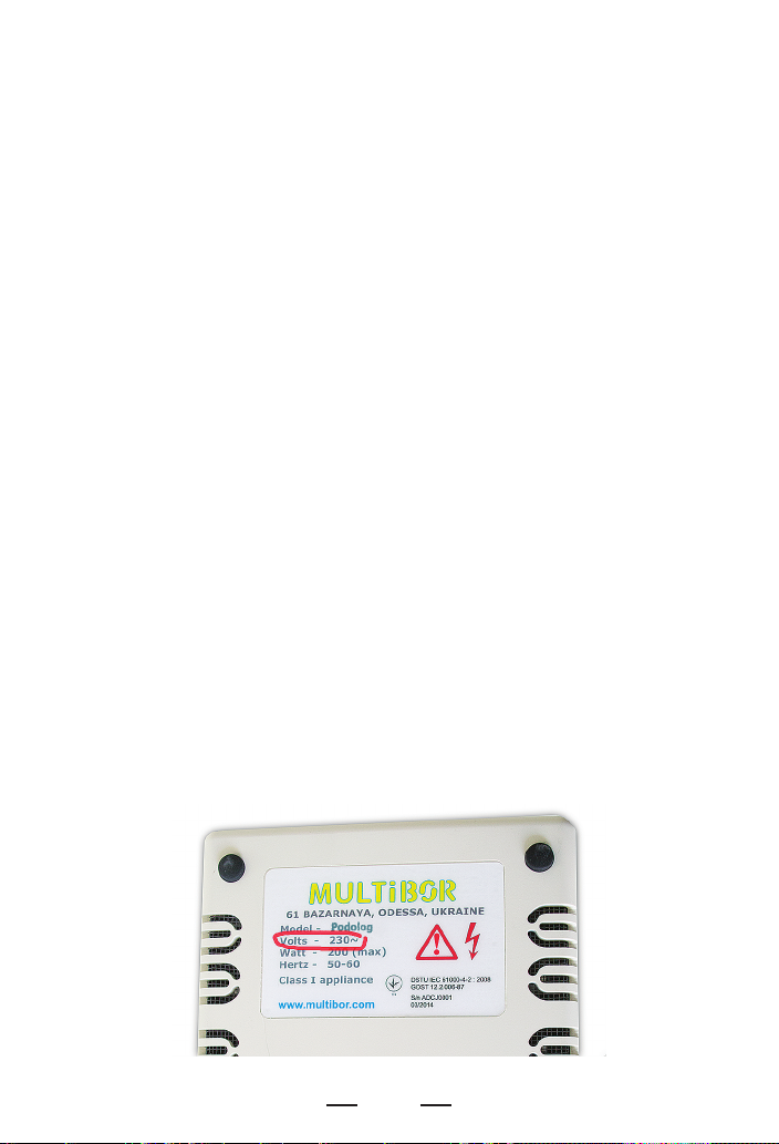
The voltage and frequency of the power supply mains
are shown on the device!
6
ATTENTION! Disregarding these safety precautions may damage
the Milling Cutter or may result in its ignition or in electric shock for
you.
ATTENTION! Plug the Milling Cutter in the electric mains thru
standard three-pin sockets with grounded terminals only.
Nine Simple Rules:
1. Never use electric mains where voltage and frequency are
dierent from the parameters specied on the casing of the Milling
Cutter.
2. Do not try to plug or unplug the Milling Cutter with wet hands.
3. Always insert the plug deeply to the end.
4. Never pull the power cable to withdraw the plug out of the wall
socket.
5. Avoid damage to and do not modify and do not stretch the power
cable and the connection cable. Do not put any items onto them. The
connection cable remains under big workload while in use, therefore
it would quickly break down if used improperly (e.g. knots and loops
in the cable, constant bending at sharp angles, abrupt moves).
6. Do not switch the Milling Cutter on if the power cable or
connection cable is looped or knotted.
7. Do not plug the Milling Cutter in a wall socket, which is used to
provide power to some other equipment (via extension cables,
T-junctions, etc.)
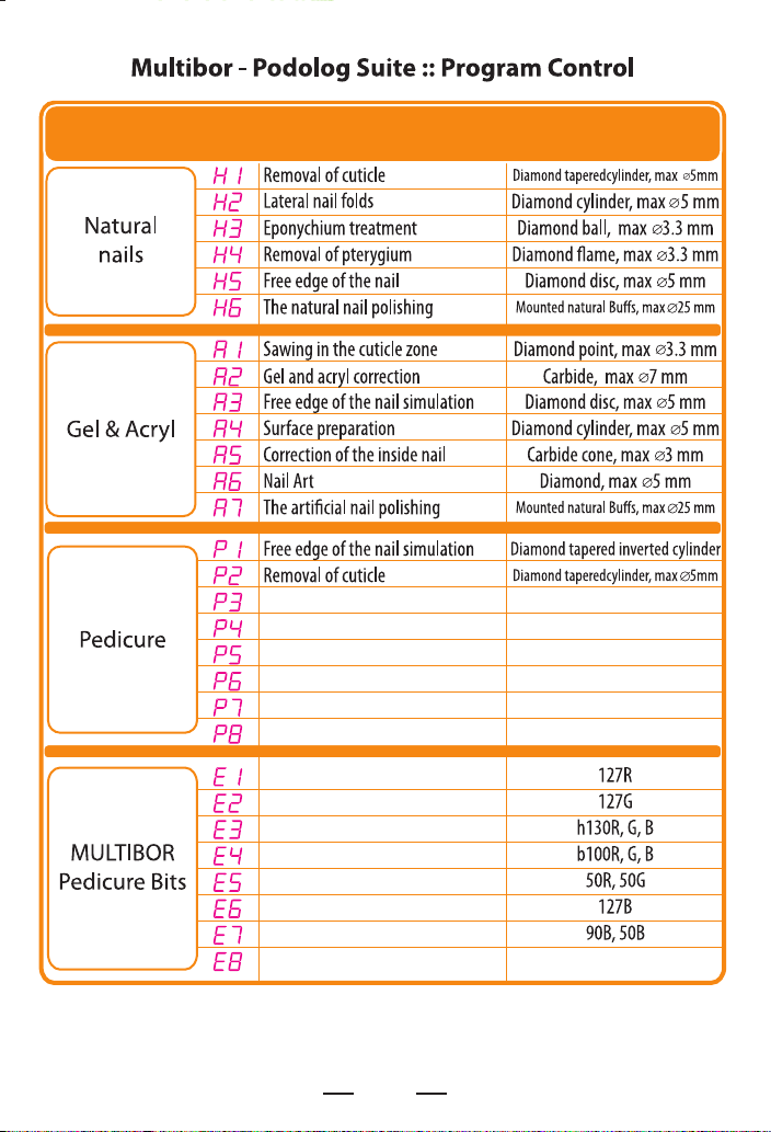
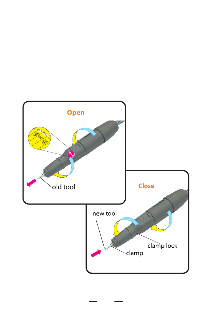
8. Use high-quality and properly operating tools (caps, milling tools,
etc.) only. Shank ends must be plain-shaped and all parts of the tools
must be rmly xed to each other. Do not use any worn tools as it
may result in their destruction.
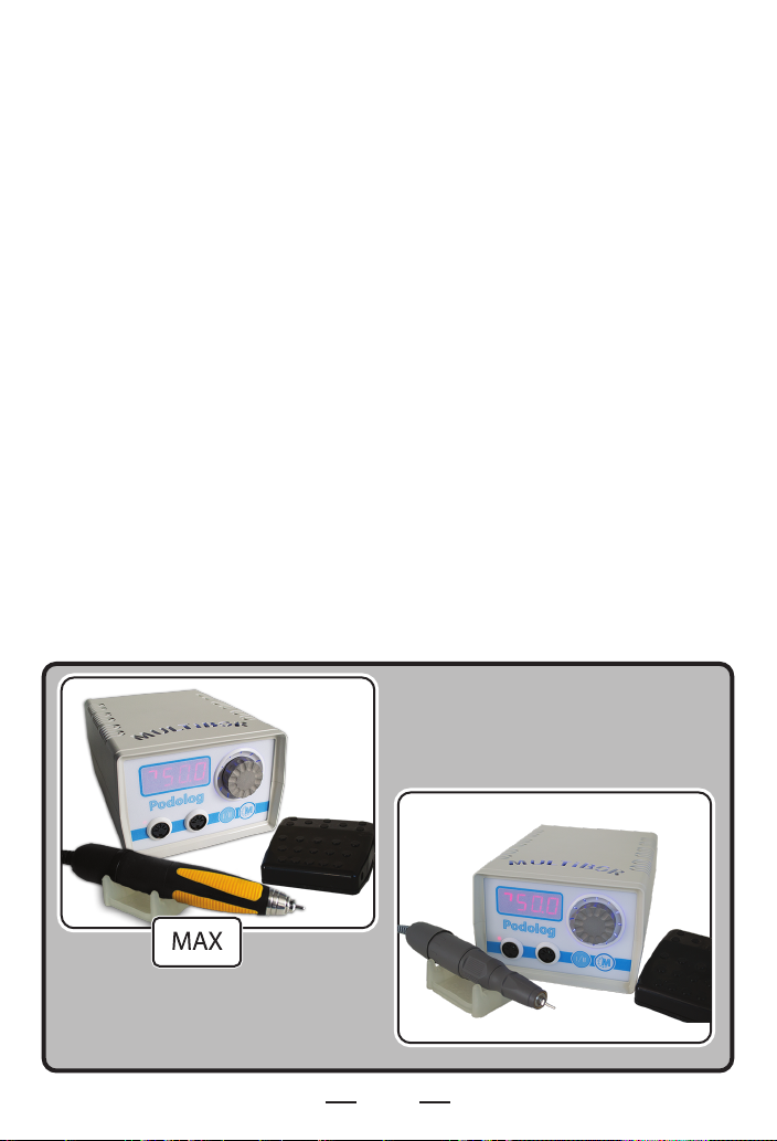
9. When selecting the operation modes for the Milling Cutter, do not
go beyond the maximum permitted limits for a specic tool as it may
result in destruction of the tool and in breakdown of the Milling
Cutter.