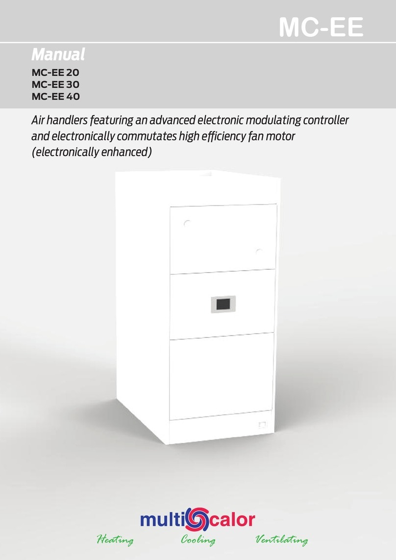
Multicalor MC-10 User manual

MC-10
Installation instructions
Installation, commissioning, maintenance and use of the appliance
Indirect air heater equipped with an energy ecient fan with DC motor

2 Modifications reserved Document: IHL_MC-10_2020
Dimensions
1
1
2
2
3
3
4
4
5
5
6
6
7
7
8
8
A A
B B
C C
D D
SHEET 1 OF 1
DRAWN
CHECKED
QA
MFG
APPROVED
Marc 7/10/2020
DWG NO
AQMC-ASSY
TITLE
SIZE
D
SCALE
REV
0.3
3
0
0
76
8
3
2
2
3
62
4
02
5
5
0
2
1
7
38
4
5
0
2

Document: IHL_MC-10_2020 Modifications reserved 3
1
1
2
2
3
3
4
4
5
5
6
6
7
7
8
8
A A
B B
C C
D D
SHEET 1 OF 1
DRAWN
CHECKED
QA
MFG
APPROVED
Marc 28/10/2020
DWG NO
AQMC-ASSY-1
TITLE
SIZE
D
SCALE
REV
0.4
2
13
4
8
5
6
7
10
9
Exploided view
Legenda
Number Description
1 Filter cover
2 TFT touch screen panel
3 Filter
4 D3G160 system blower
5 PCB
6 Temperature sensor : return air
7 Heat exchanger
8 Temperature sensor : supply air
9 Hot water return to heat source
10 Hot water flow from heat source

4 Modifications reserved Document: IHL_MC-10_2020
The Multicalor MC-10 air handling units are indirectly fired air hea-
ters. The units are equipped with generously sized heat exchan-
gers with 6 rows. This ensures that even at low water tempera-
tures sucient high air temperatures are achieved. The units are
therefore extremely suitable to be used with modern condensing
boilers with reduced water temperature. Of course you can also
use them for district heating.
This appliance excels by its timeless sleek design and a neutral
white lacquered sheet steel casing. Unique to this device is the
advanced control unit. The control optionally allows thermostats
and air valves up to 4 zones independently of each other to
control.
By using electronically controlled DC motors, the power con-
sumption is greatly reduced so that the environment is spared
and you consume considerably less electricity.
The fan of the MC-10 is located on the pressure side of the
system. This ensures that the fan is always optimally cooled and
the service life of the motor bearings is extended. Due to a well
thought-out design, the heat exchanger compartment is extre-
mely well insulated with 15 mm thick insulation, thus limiting
heat losses.
The units are delivered almost ready to use. It suces to connect
the supply and return pipes of the hot water, the air ducts and
the power lines on site.
The MC-10 air heater is supplied in DOWNFLOW (lower blowing)
version, but can be installed in UPFLOW version (upper blowing).
1 General information
2 Technical data
2.1 General technical data
The air heaters are CE labelled and comply with the Machinery
Directive 89/392/EEC, the Low Voltage Directive 73/23/EEC, the
EMC Directive 89/336/EEC. The fans used comply with the ErP
directive 2009/125/EEC, requirement 2015.
2.2 MC-10 air heater
MC-10
Blower Type D3G160
Power Watt 170
Nominal rated output kW 10
Nominal flow rate m³/h 600
Air on temperature °C 20
Air o temperature °C 71,9
Water supply temperature °C 80
Water return temperature °C 73
Water flow rate l/s 0,37
Dimensions mm 768 x 300 x 550
Weight kg 27
Electrical supply 230 V~, 1P+N , 50Hz

Document: IHL_MC-10_2020 Modifications reserved 5
3 Operation of the control unit
3.1 General
The MC-10 is equipped with an advanced control unit with TFT
touch screen that always informs the user about the operation of
the device.
The installer and/or the user can adjust a number of parameters
in the controller so that the devices can be perfectly adapted to
the situation in which they are used.
In principle, the installer can choose between two dierent
operating modes: the MC-10 air heater can be used as a “slave” or
as a “master”.
If the MC-10 is used as a “slave”, the device does not actively
participate in the system. Therefore, no room thermostat is con-
nected to the controller.
If the MC-10 is used as a “master”, the device actively participates
in the control. At least 1 thermostat is then connected to the
controller. In addition, a number of other outputs can be used
and controlled (such as the zone control).
The slave mode is very simple, but a number of possibilities of
the device remain unused. The master mode oers additional
possibilities (such as zone control), but this of course ensures that
the installation is slightly more extensive.
In both cases, the fan speed is normally automatically adjusted
according to the air temperature and the selected operating
mode.
3.2 The control panel
3.2.1 Basic screen
By default, the following information is displayed on the screen:
Legenda
Number Meaning
1 Current Function Mode
2 Air temperature
3 Date
4 Time
5 Menu button settings
6 Menu button information
Multicalor 11-10-2017
18°
19:48
3=
1
3
2
5
4
6

6 Modifications reserved Document: IHL_MC-10_2020
3.2.2 Changing settings
Pressing the settings icon 3displays the first screen of the menu.
Multicalor 11-10-2017
18°
19:48
3=
18°
13-03-2017
Buiten
1
Settings
36
45
Systems
Air handling unit
Screen cleaning
Legenda
Number Meaning
1 System Settings
2 Settings regarding the operation of the MC-10
3 Screen cleaning
4 Back to the home screen
3.2.3 Changing air heater settings
1
Air handling unit
36
45
System blower
Advanced settings
Zone control
7
7
Under “Air handling unit” you can set the minimum, medium and
maximum fan speed and temperature of the MC-10 air heater.
1
System blower
36
45
Fan curve (CH)
Air flow (CH)
Summer ventilation
Cooling 7
3.2.3.1 Low, average or high temperatures
On the MC-10, 3 air temperatures can be set: low, medium and
high. To set these values, press the menu button settings, air hea-
ter, system fan and then the first option “fan curve” in the menu.
1
Fan curve (CH)
36
45
Low speed at:
Medium speed at:
High speed at:
30.0°
40.0°
55.0°
9 :
On the right side of the screen, you can select the low, medium or
high speed options by pressing the value next to them.
The selected value is displayed in orange. Pressing the Sor R
buttons changes the set value.
Pressing 1automatically saves the changes and exits the menu
screen.
1
2
3
4

Document: IHL_MC-10_2020 Modifications reserved 7
3.2.3.2 Low, medium and high speed
On the MC-10, 3 airspeeds can be set for heating: low, medium or
high value. To set these values, press the menu button settings, air
heater, then system fan and then the “Air flow” option.
Luc
1
Air flow (CH)
36
45
Low:
Medium:
High:
10%
50%
80%
9 :
The selected value is displayed in orange. Pressing the Sor R
buttons changes the set value.
Pressing 1automatically saves the changes and exits the menu
screen.
3.2.3.3 Relationship between the air temperature and air
speed, fan curve
10% 20% 30% 40% 50% 60% 70% 80% 90%0%
30°
35°
40°
45°
50°
55°
60°
25°
1
2
3
4 5 6
The relationship between the air temperature and air speed is dis-
played in the above graph. If the air temperature is lower than the
“low value” (3) parameter, the blower is operational at the “low”
(4) speed. If the air temperature is higher than the “high value”
(1) parameter, the blower is operational at the “high” (6) speed.
In-between these values, the speed of the blower is automatically
adjusted based on the air temperature.
The “average value” (5) and “average” (2) parameters serve as an
additional checking point to ensure you have more control over the
air flow rate.
3.2.4 Change system settings
13-03-2017
Toerental
1
System
36
45
Time
Date
Language
Display
Under “system” you can set some basic settings.
3.2.4.1 Set language
The control can be set to dierent languages. To access this set-
ting, press the system button in the settings menu and then press
the third option.
1
English
Language
9 :
The selected value is displayed in orange. Pressing the Sor R
buttons changes the set value.
Pressing 1automatically saves the changes and exits the menu
screen.
3.2.4.2 Setting the time and date
Analogously, you can adjust time and date mode.
3.2.4.3 Change screen rotation
Under “Settings-System-Display” you will find the possibility to
rotate the screen 180°.
This is necessary if you change the unit to an upward blowing
version.
Then change the value from 0 to 2 at screen rotation.
Pressing 1automatically saves the changes and exits the menu
screen.
It is only after leaving the screen that this rotation is executed.

8 Modifications reserved Document: IHL_MC-10_2020
Luc
1
Display
36
45
Brightness:
Sleep mode:
Display rotation:
100%
240
0
9 :
3.2.5 Cleaning the screen
Pressing the Screen Cleaning button temporarily turns o the
touch screen for cleaning. Clean the screen with a microfiber cloth
or a paper towel.
Screen cleaning
Screen cleaning ends in : 10
3.2.6 Installer menu
Certain parameters are in an installer’s menu to prevent ill-
considered changes. This installer menu is only accessible after
entering a code.
Legenda
Code User lever
123456 Power user
007007 Installer
The code for user level “technician” is only released after fol-
lowing a training course at Multicalor.
Under normal circumstances it is not necessary to make any
changes to this menu.
3.2.7 Summer ventilation
If the unit is used as a master, it is possible to switch the unit into
ventilation mode with an external contact, for example GR on
the A3100.
The blower then runs at the speed set in the summer ventilation
parameter “Settings-System blower-Summer ventilation”.
3.2.8 Locking
If an error occurs that endangers the safe operation of the unit,
the unit is locked. The cause of the lock is displayed on the screen.
LucHeater lockout
NTC 1 error
6
7
The lock can be released by pressing the release button. However,
if the fault is not resolved, the unit will lock again.
You should then contact your installer or the manufacturer for a
solution.
3..9 Information screens
By pressing the information button in the main menu you can
view a number of information screens such as system version,
NTC probes, blower, etc.
1
Information
36
45
System version
System blower
Temperatures
NTC

Document: IHL_MC-10_2020 Modifications reserved 9
Important!
IPlease note that the installation of the air heater may only
be carried out by a qualified installer.
IIn addition, the installation must be carried out in accor-
dance with the latest edition of all local standards and the
installation instructions of the respective appliance.
IFurthermore, make sure that the conditions of the local
distribution network (electricity and hot water) correspond
to the settings of the appliance before installation or
commissioning.
4.1 General
4.1.1 Transport damage
Please check the air heater for transport damage upon delivery.
If damage is found, please state this on the carrier’s delivery note.
Make sure that the driver confirms your findings. You will then
warn your supplier in writing. Damage that has not been establis-
hed on the waybill cannot be taken into account afterwards.
4.1.2 Packaging
The air heaters are packed in a box made of recycled cardboard.
Do not throw away the packaging but oer it for further recycling.
4.1.3 Installation guidelines
Observe the following guidelines when determining the position
of the air heater:
• Place the unit centrally in relation to the duct system;
• Place the unit on a flat and solid subfloor;
• On a damp floor, the unit must be placed in a raised position;
• Always install the unit in isolation from the building structure
to avoid transmission of noise and vibrations.
Warning:
IThe appliance must be level!
IThe appliance must be installed in a frost-free environment!
If impossible, protect the water circuit against frost damage.
IEnsure that no aggressive and/or flammable products (such
as chlorine, bleach, petrol, etc.) are installed in the
installation room.
IWhen using a free return, no open-circuit appliances may be
present in the installation room!
4.1.4 Minimum clearance around the appliance
Observe the following minimum clearances when setting up the
device:
• Keep 50 mm clearance around the unit;
• Keep a clearance of at least 50 mm around the hot water
supply pipes and any combustible material.
• At least 700 mm of service space must be provided at the
front of the appliance (ensure a comfortable standing
height).
4.1.5 Transportation on site
Move the appliance on site using a trolley.
IThe air heaters must under no circumstances be moved by
tilting at the corners. The casing of the unit can be irreparably
damaged by this. This damage is not covered by the war-
ranty of the appliance.
4 Installation
4.2 Structure
To set up the system as a downflow version, proceed as follows.
4.2.1 Installation of the discharge plenum (optional)
• Place a vibration-damping material, e.g. a sturdy rubber mat
of +/- 20 mm thickness, on the floor.
• Remove the bottom of the plenum if the departure channel
is connected to the bottom. A cut out has been applied so
that this is relatively easy to achieve.
• Of course, you must also make an opening in the vibration-
damping mat if present!
• Then place the discharge plenum and any lateral discharge
channels.
• Seal everything with neutral silicone.
4.2.2 Installing the filter cover handle
By placing the thumbs on the corners of the filter cover it is pos-
sible to tilt the filter cover open.
The handle is easy to screw into the provided holes.

10 Modifications reserved Document: IHL_MC-10_2020
4.2.3 Opening the heat exchanger housing
The heat exchanger connections are accessible after removing
the access panel.
4.2.4 Connecting water pipes
After opening the housing, the water pipes can be connected.
The diameter of the water pipes is 22 mm.
There are 3 possibe water pipe leadtroughs : left, right and upper
left. Included blind grommets ensure an airtight seal of the heat
exchanger compartment.
4.2.5 Removing the heat exchanger
It is possible to remove the heat exchanger from the steel
cabinet. This can be interesting for several reasons : replacing a
defective heat exchanger or blower, connecting the pipes during
installation, ...
Remove the two hexagon socket head cap screws at the battery
level (encircled) with an open-end spanner 8.
After this it is possible to extend the entire inner construction
(heat exchanger + blower). A slight upward movement should be
carried out.
4.3 Electrical installation
4.3.1 Supply voltage
The MC-10 operates on an electrical power supply of
230VAC~50Hz.
Attention:
IDo not switch on the power supply until all cables are
correctly connected.
4.3.2 Connecting the MC-10 air heater
4.3.2.1 General (master and slave)
The connections of the air heater are made in the fan compart-
ment. Remove the filter access panel and filter. Then remove the
shield plate so that you can see the PCB.
If the unit is switched as “slave”, this is sucient for connections.
If the appliance is switched as a master, you must still connect at
least one thermostat. You should also loop the control signal to
the group pump or combination boiler.
4.3.2.2 Thermostats
If you wish to use the device as a master, you must connect at
least 1 thermostat. The unit works optimally together with the
electronic clock thermostat A3100. This thermostat is suitable
for heating, cooling and ventilation and is specially designed for
use with air heaters. Connect the thermostat according to the
instructions on the schedule. Adjust the switching speed of the
A3100 so that the thermostat switches 12 times per hour.
IAttention: the A3100 has a bridge between R and Rc at the
factory. Do not remove this bridge!
You can connect a maximum of 4 thermostats to the control
system. Each thermostat can then be connected to its own air
flow. By means of an optionally available expansion PCB, 4 stop
valves (equipped with servomotors) can be controlled so that
a 4-zone control can easily be built. You must order an optional
expansion PCB.
If you wish to use a dierent thermostat, only use models with
potential-free contacts. You generate heat demand with contact
WR and cooling demand with contact YR. Consult the diagram
for more information.
Mount the room thermostat at about 1.6 m height, centrally in
the room and easily accessible for normal air circulation in the
room. Always mount the thermostat on an interior wall where it
is not influenced by other heat sources such as air vents, electrical
appliances, direct sunlight, etc. The installation near windows,
doors, close (<1.20 m) to an external wall or under or close to
a staircase is also not recommended. For more information on
installation and programming, please refer to the operating
instructions of the thermostat.

Document: IHL_MC-10_2020 Modifications reserved 11
4.4 Installation of the duct system
4.4.1 Installation of pulse channels (discharge)
The air ducts must be connected to the hot air distribution box.
For UPFLOW models, the hot air distribution box is placed on top
of the unit. With a DOWNFLOW appliance, the hot air distribution
box is placed BOTH the appliance.
Like the duct system, this air outlet plenum must be suciently
insulated to limit pipe losses.
The ducts must have a sucient cross-section for the displaced
air volume. All air ducts, including the grille shoes, must of course
be insulated.
4.4.2 Installation extraction ducts (suction)
You can choose to take air from the top or side of the device.
When side return installation, a special side return air kit needs to
be fitted.
When using the unit in standard downflow situation, the flanges
on the top need to be folded upways to create a return frame for
the ducts.
If you use an open return, there must be no appliances with an
open combustion chamber in the boiler room. Otherwise, you
must connect a return duct to the MC-10.
Attention:
INever use the MC-10 without an air filter! This can damage
the heat exchanger irreparably.
When using an open return, it is best to install the corresponding
silencer.
4.3.2.3 Installation “slave”
1
3
22
4
2
5
Legenda
1 MC-10
2 Boiler
3 Room thermostat
4 Single way valve and adjust-
ment valve
5 Small buer tank min.40l
Notes to the scheme of principles
IMake sure that you connect the heat exchanger in counter-
flow. The hottest water should be connected to the connec-
tion farthest from the fan.
IAlways consult the manual of the water boiler before
installing it.
IComponents such as boiler pump, dirt trap, air vent, etc. are
not shown in our schematic diagrams. These components
must of course be present, consult the boiler manufacturer if
in doubt.
IFor some boilers, it maybe necessary to add a small buer
tank. This allows a boiler more time at start up to stabilize
before modulation and prevent short cycling.
4.3.2.3 Installation as “master” with group pump
This method of connection is often used when a common boiler
serves several residential units. The room thermostat is connec-
ted to the MC-10, which releases a potential free contact (max.
8A) to switch on a group pump.
3
22
5
4
2
61
Legenda
1 MC-10
2 Boiler
3 Room thermostat
4 Single way valve and adjust-
ment valve
5 Group pump
6 Small buer tank min.40l
Notes on the principle diagram
IThe points raised in section 4.3.2.3 also apply here.

12 Modifications reserved Document: IHL_MC-10_2020
5 Maintenace
5.1 Maintenance by the end user
5.1.1 Cleaning the air filter
The standard air filter is a synthetic air filter with a life span of 1
year. However the filter requires monthly cleaning, to be perfor-
med as set out below:
• Set the thermostat 5°C lower than the environment tempe-
rature.
• You may wait until the apparatus has cooled down.
• Disconnect the mains.
• Remove the air filter and use a vacuum cleaner to clean it
• Put the filter back into the machine.
• Restore the mains.
• Set the room thermostat again to the required value.
Never remove the air filter from an MC-10 unit. The machine must
always be fitted with a EU3 (or better) air filter. Heating or venti-
lating without a filter may pollute the heat exchanger to such an
extent that the machine may incur irretrievable damage, which
the warranty does not cover.
5.1.2 Cleaning the casing
The casing may be cleaned with a soft humid cloth. Do not use
aggressive media such as bleaching water, solvents or petrol, as
these products are likely to damage the paint.
5.1.3 Cleaning the display
The touch screen can be temporarily switched o for cleaning
by pressing the clean screen button. Clean the screen using a
microfibre cloth or with a paper tissue.
5.2 Maintenance by the installer
The unit is nearly free of maintenance. It is sucient to replace
the air filter and to check the unit for leakage and proper
functioning.
• Set the thermostat 5°C lower than the environment
temperature;
• You may wait until the apparatus has cooled down;
• Disconnect the mains;
• Remove and replace the air filter;
• Check unit for functioning and check for leaks;
• Verify pressure in the supply lines;
• Switch mains power on;
• Set the room thermostat again to the required value

Document: IHL_MC-10_2020 Modifications reserved 13
6 Electrical wiring
BURNER
HEATPUMP ON
Switch HEAT/COOL
L/N/PE
C/Rx/Tx/V
FAN
THERMOSTAT
W
G
R-Rc
Print 0D1
Flat Cable
Heat (I1)
Venlaon (I3)
Return Air
Supply Air
Ground (GND)
Brown
Blue
Green/Yellow
230VAC/16A
Y
Cool (I2)
SW1
1 2 3 4
ON
ALL 4 OFF
PE
PE
N
L
L
N
GND
GND
O1
I1
I2
I3
Print 0DA_MC
NTC2
NTC2
NTC1
A
NTC1
B
GND
+V12
FAN J7
DISP J6
NO
COM
0-10V DC
GND
Common
Heat
Cool
Vent
POT
SW1
NC
NO
COM
NC
NO
COM
NC
RE-AC RE-HP RE-HT
FN
FN
BERT2
1 2 3 4
ON
UNIT FUSE
MC-10 6A
MC-14 6A
MC-20 10A
MC-30 10A
MC-40 16A

14 Modifications reserved Document: IHL_MC-10_2020
7 Warranty
7.1 General
Multicalor Industries NV guarantees the MC units against all ma-
nufacturing defects or material faults, subject to the terms and
conditions described under ‘Scope and duration of the warranty’.
Moreover Multicalor Industries NV guarantees the machine will
achieve the output indicated in normal conditions.
7.2 Scope and duration of the warranty
The warranty starts at the moment of purchase by the first user
and entitles the beneficiary of the warranty, through the dealer or
the service department of Multicalor Industries NV, to:
• One (1) year free exchange of faulty parts;
• Five (5) year free exchange of the heat exchanger, but exclusive
of labour costs and travel expenses.
Replacement of parts does not change the initial warranty
period, i.e. the warranty is not extended by the replacement of
faulty parts.
7.3 Damage that is not covered by the
warranty
All damage resulting from:
• Machine use which does not match normal household or
light commercial use;
• Failure to meet the user instructions as summed up in the
user manual;
• Insucient or wrong maintenance;
• Irretrievable fouling up of the heat exchanger caused by he-
ating, ventilating or cooling with a highly fouled up or absent
dust filter;
• Modifications or adaptations to the machine not covered by
prior written approval by Multicalor Industries NV;
• Repairs carried out with non-original parts or wrong equip-
ment or materials;
• The heat exchanger when used in an atmosphere polluted
with chlorine or other chemicals;
• Causes foreign to the machine, including (but not restricted
to):
1. Damage incurred during transport, including
dents, scratches, etc.;
2. Damage caused by disasters, including fire,
lightning, flooding;
3. Damage linked to frost;
4. Damage caused by a departure from the
normal power voltage, or water or pressure
deviating widely from the nominal
values suitable for the normal supply of the
machine;
5. Damage caused by a non-conformity of the
installation to the local standards
applicable.
7.4 Not covered under warranty
• Parts subject to normal wear, including air filters, fuel filters
and other parts that have to be replaced periodically;
• Machines the serial number of which has been removed or
altered;
• Travel expenses and labour costs if the matching warranty
period has expired;
• Result damage caused by the faulty machine;
• Any loss of productivity attributable to the faulty machine;
• Any loss of use caused by a fault to the machine;
• When the machine proves unsuitable for the purposes for
which the purchaser bought the machine.
7.5 Repairs
During the warranty period the customer may call upon the
services of the dealer who sold the machine or, in Belgium, to the
“after-sales” department of Multicalor Industries NV.
7.6 Service-parts
If it is necessary to replace a part, we recommend that the
matching article code of the part concerned be mentioned on the
order, in addition to the type of air heater, the machine’s serial
number as well as the name of the part concerned. The machine
type and serial number are mentioned on the registration plate
placed in the machine.

Document: IHL_MC-10_2020 Modifications reserved 15
Multicalor Industries declares that the water-fired air heater MC-10 complies with the Machinery Directive 89/392/EEC, the Low Vol-
tage Directive 73/23/EEC and the EMC Directive 89/336/EEC.
The fans used comply with the ErP directive 2009/125/EEC, requirement 2015.
8 Declaration of conformity

For more information, please contact your installer:
Date of last change
4/11/2020
Manual MC-10
Modifications reserved
Multicalor Industries NV • Blarenberglaan 21 • B-2800 Mechelen (Belgium)
www.multicalor.be • Tel.: +32 15 29 03 03 • Fax: +32 15 29 03 20 • info@multicalor.be
Table of contents
Other Multicalor Air Handler manuals
Popular Air Handler manuals by other brands

Deekax
Deekax TALTERI DIVK-C 91 CD Installation and user manual

Vents
Vents MICRA 80 A3 user manual

United Technologies
United Technologies Carrier 39CQ manual

OSTBERG
OSTBERG HERU IQ S Series Installation

Parameter Generation and Control
Parameter Generation and Control 9354-4250 Installation and operation manual

Dantherm
Dantherm TKS 60 Service manual

Geostar
Geostar GAH022 installation manual

Daikin
Daikin UATYQ25ABAY1 Operation manual

McQuay
McQuay Skyline OAC 003G Installation and maintenance manual

Mitsubishi Electric
Mitsubishi Electric PAC-AH63 installation manual

IV Produkt
IV Produkt Envistar Flex Assembly instructions

EMI
EMI UNHV09 Installation, operation and maintenance manual