MultiDyne HUT-APE User manual

Table of Contents
Table of Contents .................................................................................................................................. 2
Declaration of Conformity ...................................................................................................................... 3
Safety Info ............................................................................................................................................. 4
1. Overview ........................................................................................................................................ 6
2. Feature Descriptions....................................................................................................................... 7
3. HUT-BS (CCU Side)..................................................................................................................... 13
4. SilverBack-APE............................................................................................................................ 14
5. Applications.................................................................................................................................. 15
6. Moving the Fiber Plate.................................................................................................................. 16
7. Panasonic Fiber I/O...................................................................................................................... 18
8. Accessories.................................................................................................................................. 20
9. Troubleshooting...............................................................................Error! Bookmark not defined.
10. Specifications............................................................................................................................ 22
Contact Info......................................................................................................................................... 25
Copyrights ........................................................................................................................................... 26
Document Revisions
Revision
Description
Date
Author
A
Initial
5/5/22
SDP

Declaration of Conformity

Safety Info

Laser Safety Information
Warning –Use of controls, adjustments, or performance of procedures other than those specified herein may result in
hazardous radiation exposure.
Warning –Never look directly into the end of the optical fiber while either end of the system is operating.
Warning –Never clean an optical fiber connector on equipment or cable that is carrying light.
Warning –Always use dust caps on fiber optic connectors when cables are not connected. This will protect the connector from
damage and accidental exposure of a human eye to an operating laser.

1. Overview
The HUT-APE system is an HDTV camera power supply compatible with multiple, popular HDTV
camera manufacturers. It enables you to replace long runs of the bulky and expensive hybrid fiber
cable that connects your camera and CCU with inexpensive fibers alone. It does this by moving the
camera power injection from the CCU side to the cam side. It consists of a breakout adapter, known as
the HUT-BS, that attaches to the SMPTE connector on your CCU. This enables you to connect two
fibers going to the cam side using ST connectors, and it also tricks the CCU into thinking that your
camera is still attached by the hybrid fiber cable. At the cam side of these fibers is the HUT-APE, which
takes these two fibers and routes them to a SMPTE hybrid fiber connector. It also plugs into local mains
power and injects various DC voltage for your camera into that same SMPTE connector, which now
connects to the camera via a much shorter length of hybrid fiber cable. The HUT-APE performs the
same safety checks on this cable as your CCU does, and it also allows remote powering down of your
camera from the CCU side.
Key Features
•High-efficiency power supply delivers up to 325W of power
•Natively compatible with specific Sony, Grass Valley, and Panasonic Camera models
•2RU tall, 1/3 RU wide form factor allows three units to fit in standard 19” rackmount side-by-side
•Dual AC inputs provide auto-failover protection preventing camera dropouts
•Built-in optical power meter for easy system setup and status monitoring
•Fiber patch panel is interchangeable between the front or rear panel

2. Feature Descriptions
2.1. Front Panel
A. POWER CONTROL
CCU (REMOTE) –This switch position selects the HUT-APE operating mode to monitor the optical
power received from the CCU and use it as a mechanism to electronically switch the output voltage,
thereby enabling remote ON/OFF control capability for the connected camera.
HUT (LOCAL) –This switch position enables the HUT-APE to switch the output voltage on or off
based solely on the sense line control signals from the camera.
B. MODE
Upon power-up, or whenever the unit is powered on with no SMPTE cable attached, the HUT-APE
enters the “search” mode, monitoring the SMPTE port for a valid load device connection (Multidyne
APE; Grass Valley, Sony, or Panasonic Cameras). When one of these products is detected, the
HUT-APE will halt searching, configure itself for the detected load’s operating parameters and
illuminate the appropriate LED. The SONY switch must be set to the appropriate model series
(1K/2K/4K OR 3K) for correct camera detection.

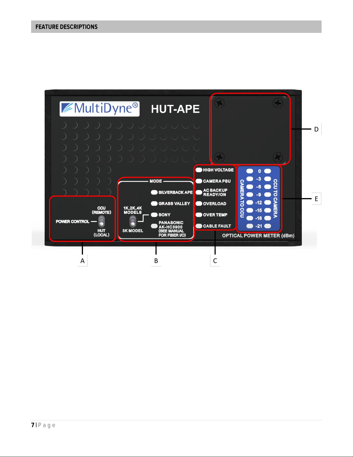
SILVERBACK APE –Green LED indicating the Multidyne Advanced Power Extender (APE) is
connected to the SMPTE output.
GRASS VALLEY –Green LED indicating a Grass Valley LDX camera is connected to the SMPTE
output.
SONY –Green LED indicating a Sony 1K, 2K, 3K or 4K series camera is connected to the SMPTE
output.
PANASONIC AK-HC3900 –Green LED indicating a Panasonic AK-HC3900 camera is connected
to the SMPTE output. See Section 7 for reference on the note about Fiber I/O.
C. Status Indicators
HIGH VOLTAGE –This indicator is off when the HUT-APE is in the start-up/standby mode (i.e., low
voltage output), lights up green when the camera is connected with its power switch in the ON
position, and red if the high voltage is on but the output voltage is lower than the specified operating
range.
Each of the camera systems, as well as the Multidyne APE power supply, initially power-up using a
low voltage in the 15 –45 VDC range to operate low power detection and startup circuitry providing
a handshake between the camera and the CCU thereby establishing a valid connection.
CAMERA PSU –Lights up red when no communication has been established between the HUT-
APE and one of the above compatible devices or green when a functional link is detected.
AC BACKUP READY/ON –Off if no secondary/backup source is present; lights up green when the
HUT-APE is operating on the main power source with the backup power source present (“normal”
dual AC source operating mode), lights red when the main power has dropped/failed with the unit
now relying on the backup power source, and then alternates between red and green when the
main power source is re-applied, and monitored for 30 seconds to verify stability before another
seamless transition back to the main power source; in which case the LED returns to solid green.
The HUT-APE is equipped with “Main” and “Backup” AC inlets that provides seamless transition to
a secondary AC mains power source in case the main power source either drops below the
specified operating voltage range of the HUT-APE (brown-out condition) or fails completely. No
variation in the HUT-APE output voltage will occur, thereby maintaining glitch-free video/sound
performance from the connected camera system.
OVERLOAD –Off under normal operating conditions, lights up red when the HUT-APE output is
loaded beyond 90% of the total output rating, and flashes between red and orange if the over-
current detection has been triggered, placing the HUT-APE in the 20 second retry interval cycle.
OVER TEMP –This Indicator displays multiple fault conditions related to the cooling of the HUT-
APE
1. Locked rotor indication –If the rotor is locked by an obstruction or failure of the motor, the
LED will light red.
2. Internal overheating –If the internal operating temperature exceeds a safe limit for the
electronic components, the LED will flash red as the HUT-APE enters a 2-minute shutdown

period (high voltage to camera is disabled) to allow for cooling. If the internal temperature has
returned to safe operating level after this time, the output power will be re-applied. If the internal
temperature does not recover from the overheated condition, the output will remain off and the
LED will continue to flash red.
CABLE FAULT –Lights red if the SMPTE cable: 1. Is not connected to one of the specified
cameras or APE power supply (cable open), 2. Has an internal electrical conductor broken (cable
open), or 3. Has a short between any of the internal electrical conductors (cable shorted).
The HUT-APE checks and monitors conditions of the SMPTE cable during both the “search” phase
and while in normal operation (high voltage output enabled). Each of the internal conductors are
monitored, the red and gray sense wires, the black and white power wires, and the ground shield.
When a fault is detected in the standby/startup mode (low voltage output), the HUT-APE will
prohibit the high voltage output from being enabled. If the system is already in normal operation and
a fault occurs, the high voltage will immediately be disabled, and the HUT-APE will protect itself
from output short conditions.
D. Fiber Plate
The fiber port connections can be installed on the front or rear panels to conveniently handle
various installation requirements. See the Moving the Fiber Plate section for details.
E. Optical Power Meter
Two columns of 8 LEDs each form meters to display the optical power level in dBm for both the
CCU-to-Camera and the Camera-to-CCU fiber optic paths.
This example shows a good operating status. The optical power from both the CCU and camera
is at -6 dBm.

This graphic shows the LED display change as the range of optical power, from overload (>0
dBm) to minimum detectable signal (-21 dBm), changes. Optical power greater than 0 dBm will
cause all the LEDs to blink red. Optical power less than -21 dBm cannot be read on the meter.

2.2. Rear Panel
F. Fiber Plate
The HUT-APE has multiple fiber I/O options, including ST/UPC, LC/UPC, SC/UPC, or Neutrik®
opticalCon®Duo. By default, it is installed on the rear panel from the factory. The fiber port plate
can be moved to the front panel to conveniently handle various installation requirements. See
the Moving the Fiber Plate section for details.
G. Lemo®SMPTE 304M Plug (FXW.3K.93C)
Power Supply Output. Connect directly to camera or Silverback APE with SMPTE ST311 hybrid
cable.
H. MAIN AC Input
Primary AC power input. If only one power source is available, use this input.
I. BACKUP AC Input
Secondary AC power input. Connect to backup generator or other power source.

2.3. Connection Diagram
A. HUT-APE
B. HUT-BS (See section HUT-BS)
Connect hybrid connector to CCU hybrid connector either directly or with SMPTE ST 311 patch
cable.
C. SINGLEMODE FIBEROPTIC CABLE
Connect dry (unpowered) fiber cables between the fiber connector(s) on HUT-BS and the "dry"
fiber connector(s) on the HUT-APE.
D. HYBRID FIBEROPTIC SMPTE ST 311 CABLE
Connect a length of hybrid fiber cables between the HUT-APE and the hybrid connector on the
camera / Silverback-APE.
E. PRIMARY AC
Use the included AC power cable to connect HUT to AC mains.
F. SECONDARY AC
Use the included AC power cable to connect HUT to backup generator.

3. HUT-BS (CCU Side)
The Base unit, known as HUT-BS, has a SMPTE hybrid receptacle panel mount connector for
connection to the CCU and 2 ST/UPC or duplex LC connectors for the fibers to the HUT-APE. As on
the HUT-APE, the ST/LC/SC connectors are labeled FROM CCU and TO CCU. The same
considerations concerning the fiber labels should be observed, as on the HUT-APE.
The HUT-BS acts as a breakout for the optical ports in the CCU SMPTE connector. It also tricks the
CCU into thinking a camera is attached by a SMPTE hybrid fiber cable. This is necessary to enable the
CCU to leave standby mode so that it can accept video from the camera. It has 2 LEDs located on the
panel with the ST connectors, labeled Power and HV. The Power LED is green the CCU is supplying
power to the HUT-BS, and the HUT-BS is attempting to spoof the CCU. The HV LED is green when the
CCU is supplying high voltage. This means that the HUT-BS has successfully spoofed the CCU into
thinking a camera is attached. Otherwise, the CCU will not leave standby mode.
For proper operation, the HUT-BS must be set for the type of camera system being used. There are 2
versions of HUT-BS: one with dip switches, and a rugged version with metal bat handle switches. Set
the HUT-BS for the camera type according to the following tables:
Front Panel DIP Switch Settings:
Manufacturer
SW1
SW2
SW3
SW4
SW5
SW6
SW7
Grass Valley
Panasonic
down
down
up
up
up
up
up
Sony
down
up
up
up
up
down
down

4. SilverBack-APE
Future model.

5. Applications
A. HDTV SMPTE Camera
B. SMPTE Hybrid Cable. Up to 3km
C. HUT-APE
D. Singlemode fiber
E. HUT-BS
F. SMPTE Hybrid Cable
G. Camera Controller Unit (CCU)

6. Moving the Fiber Plate
The HUT-APE allows you to have the fiber patched to the front or rear panel to handle different
installation requirements. Review the following steps to relocate the fiber plate (ST/UPC shown). All
work should be performed in an ESD-safe environment. Use caution not to touch any internal
components. Do not contact any fiber-optic connector end faces.
Note: Apply medium strength thread locker on screws before closing the enclosure.
Recommended product: Permatex 24010 Medium Strength Thread Locker Blue Gel
1. Unplug the HUT-APE power cable(s) and all connected fibers. Let unit sit for 20 minutes for
internal components to discharge.
2. Remove the eight (8) screws holding the top cover.
3. Remove the four (4) screws from the UFP plate and gently pull the assembly out only an inch or
two. Watch for any fiber tension and do not pull hard if felt. Look inside the unit in the event a
fiber is caught on any components.
4. Note the positions of each fiber connector relative to marking on fiber plate. Unplug fiber
connectors from panel.

5. Remove the four (4) screws holding the blank plate on the other side of the unit.
6. Re-route the internal fibers from their original position to the new fiber plate location.
7. Connect the fibers to the same corresponding ports noted in Step 4.
8. Attach fiber plate and blank plates in the reverse order they were removed using the same
hardware found with each plate.
9. Reinstall top cover.

7. Panasonic Fiber I/O
Panasonic AK-HC3900 cameras have fiber paths that are reversed from other camera models
supported but the HUT-APE. For correct optical power metering and patching, the fiber connectors
must be moved as shown below. All work should be performed in an ESD-safe environment. Use
caution not to touch any internal components. Do not contact any fiber-optic connector end faces.
Note: Apply medium strength thread locker on screws before closing the enclosure.
Recommended product: Permatex 24010 Medium Strength Thread Locker Blue Gel
1. Unplug the HUT-APE power cable(s) and all connected fibers. Let unit sit for 20 minutes for
internal components to discharge.
2. Remove the eight (8) screws holding the top cover.

3. Swap both fiber pairs connected in the quad LC coupler.
Before (Default) || After (Panasonic)
4. Reinstall top cover.

8. Accessories
Rackmount Kit
RM-HUTCP-J48-KIT
HUT-APE Rackmount Kit.
The optionally available HUT Ears allow up to three (3)
HUT-APE units to be mounted into a standard 19” rack.
Each HUT-APE takes 2RU height and 1/3rd RU width.
(Includes all parts for any of 3 configs shown)
Table of contents
Popular Power Supply manuals by other brands

Matsusada Precision
Matsusada Precision eK-FGJ Series instruction manual

ZALMAN
ZALMAN ZM850-GVM user manual

dol sensors
dol sensors iDOL 65 Technical user guide

Meyer Sound
Meyer Sound MPS-482HP operating instructions

Vahle
Vahle VKS10 Mounting instructions - Maintenance

Thermaltake
Thermaltake TR2 500W user manual