DIS185SSI4F AIR COMPRESSOR — HOSE REEL INSTALLATION INSTRUCTIONS P/N EE60468 — REV. #0 (04/16/18) — PAGE 2
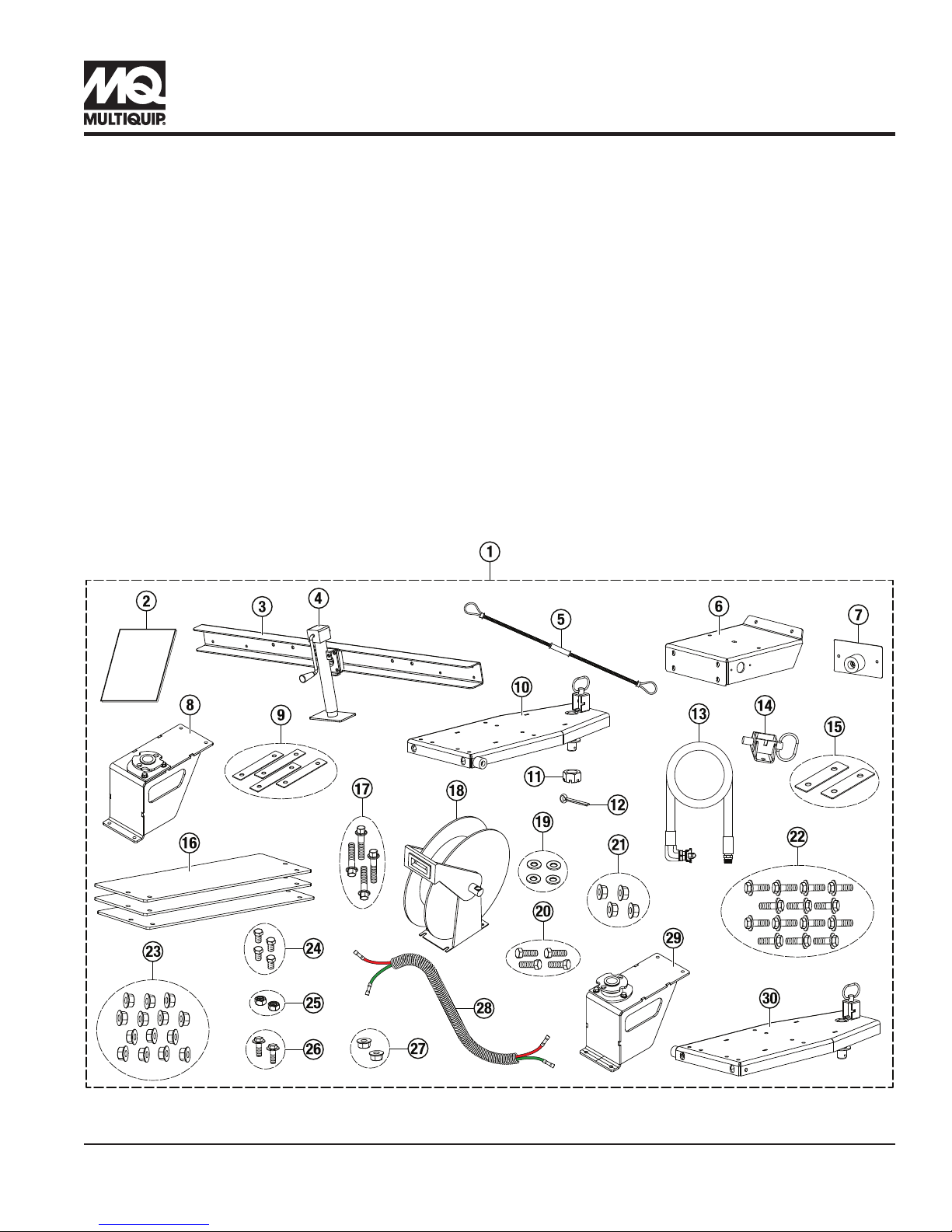
Table 1. DIS185SSI4F Hose Reel Installation Kit
Item
No. Part No. Description Qty. Remarks
1MQPSINGLEREEL50 Reel Kit Assembly, DIS185
50', Right 1Includes
items 2–28
1 MQPDUALREEL50 Reel Kit Assembly, DIS185
Dual 50' 1Includes
items 2–30
2 EE60468 Work Instruction, Reel Kit,
DIS185SSI4F 1
3 59269 Bumper Assembly,
Hose Reel Kit 1
4 29479 Jack, Sidewind 10"
Bolt-On, .5 Pin, Foot 1
5 59274 Safety Cable Hose Whip
1/8 × 20" 1Double qty.
for dual kit
6 59234 Plate, Pivot Base Mt 1 Double qty.
for dual kit
7 59267 Bump Stop Assembly,
Rear 1Double qty.
for dual kit
8 59272 Pivot Base Assembly,
Right 1
9 59286 Shim, Pivot Plate Mt,
.075 Thk 4Double qty.
for dual kit
10 59275 Reel Mount Assembly,
Right 1
11 EM968481 Nut, Hex Slotted, 1-14 1 Double qty.
for dual kit
12 38709 Pin, Cotter 3/16 × 2" 1 Double qty.
for dual kit
13 59265 Hose Assembly 1 Double qty.
for dual kit
14 59251 Lock Pin Assembly 1 Double qty.
for dual kit
Table 1. DIS185SSI4F Hose Reel Installation Kit (Continued)
Item
No. Part No. Description Qty. Remarks
15 59289 Shim, Lock Latch 2 Double qty.
for dual kit
16 59290 Plate, Tongue Ballast,
DIS185 2Qty. of 3 in
dual kit
17 42346 Bolt, HHFS,
M8-1.25 × 40 mm 4Includes
items 19–20
18 59263 Reel, 3/4" × 50',
Spring Return 1Double qty.
for dual kit
19 0447 Washer, Flat SAE, 1/2" 4
20 5218 Bolt, HHC, 1/2-13 × 1-1/2" 4
21 26328 Nut, HFS, 1/2"-13 4
22 1023 Hex Flange Bolt
3/8-16 × 1-1/4" 14 Double qty.
for dual kit
23 21781 Nut, HFS, 3/8"-16 14 Double qty.
for dual kit
24 28922-083 Screw, HHC,
M4-0.7 × 12 mm 4Double qty.
for dual kit
25 32664 Nut, Hex, M4 2 Double qty.
for dual kit
26 36720 Screw, HHFS,
5/16-18 × 3/4" Gr5 2Double qty.
for dual kit
27 49071 Nut, HFS, 5/16"-18 2 Double qty.
for dual kit
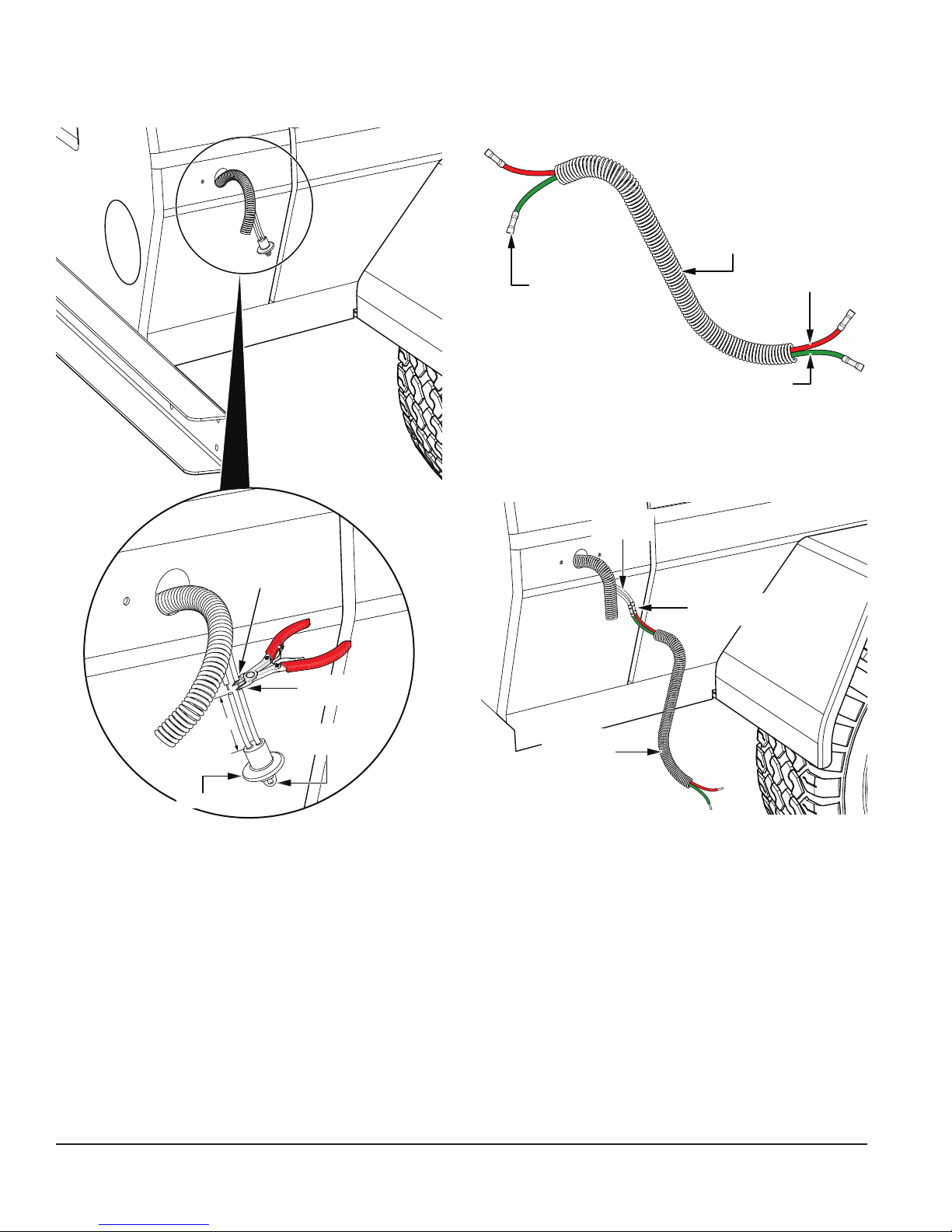
28 59291 2-Wire Extension
Harness, Split Loom 1Double qty.
for dual kit
29 59273 Pivot Base Assembly, Left 1 For dual kit
only
30 59276 Reel Mount Assembly, Left 1 For dual kit
only