MULTIQUIP G55H User manual

OPERATION MANUAL
THIS MANUAL MUST ACCOMPANY THE EQUIPMENT AT ALL TIMES.
Revision #1 (07/08/21)
MODEL G55H
GASOLINE VIBRATOR
(HONDA GX160K1QX2 GASOLINE ENGINE)
To order go to Discount-Equipment.com

We sell worldwide for the brands: Genie, Terex, JLG, MultiQuip, Mikasa, Essick, Whiteman,
Mayco, Toro Stone, Diamond Products, Generac Magnum, Airman, Haulotte, Barreto, Power
Blanket, Nifty Lift, Atlas Copco, Chicago Pneumatic, Allmand, Miller Curber, Skyjack, Lull,
Skytrak, Tsurumi, Husquvarna Target, Stow, Wacker, Sakai, Mi-T-M, Sullair, Basic, Dynapac,
MBW, Weber, Bartell, Bennar Newman, Haulotte, Ditch Runner, Menegotti, Morrison, Contec,
Buddy, Crown, Edco, Wyco, Bomag, Laymor, EZ Trench, Bil-Jax, F.S. Curtis, Gehl Pavers, Heli,
Honda, ICS/PowerGrit, IHI, Partner, Imer, Clipper, MMD, Koshin, Rice, CH&E, General Equip-
ment ,Amida, Coleman, NAC, Gradall, Square Shooter, Kent, Stanley, Tamco, Toku, Hatz,
Kohler, Robin, Wisconsin, Northrock, Oztec, Toker TK, Rol-Air, APT, Wylie, Ingersoll Rand /
Doosan, Innovatech, Con X, Ammann, Mecalac, Makinex, Smith Surface Prep,Small Line,
Wanco, Yanmar
Discount-Equipment.com is your online resource for
commercial and industrial quality parts and equipment sales.
561-964-4949
visit us on line @ www.discount-equipment.com
TO PURCHASE THIS PRODUCT PLEASE CONTACT US
Select an option below to find your Equipment
Equipment Financing and
Extended Warranties Available

PAGE 2 — G-55H GASOLINE VIBRATOR — OPERATION MANUAL — REV. #1 (07/08/21)
PROPOSITION 65 WARNING
To order go to Discount-Equipment.com

G-55H GASOLINE VIBRATOR — OPERATION MANUAL — REV. #1 (07/08/21) — PAGE 3
TABLE OF CONTENTS
G-55H GASOLINE VIBRATOR
Proposition 65 Warning ..................................................... 2
Table Of Contents ............................................................. 3
Specifications ................................................................... 4
Safety Message Alert Symbols .................................... 5-6
Rules For Safe Operation .............................................. 7-8
Operation and Safety Decals ............................................ 9
General Information ........................................................ 10
Major Components ......................................................... 11
Engine Components ....................................................... 12
Inspection .................................................................. 13-14
Startup Procedures ................................................... 15-16
Shutdown Procedures .................................................... 16
Operation ................................................................... 17-18
Maintenance .............................................................. 19-20
Troubleshooting (Gasoline Engine) ................................. 21
NOTICE
Specifications are subject to change without
notice.
To order go to Discount-Equipment.com

PAGE 4 — G-55H GASOLINE VIBRATOR — OPERATION MANUAL — REV. #1 (07/08/21)
SNOITACIFICEPSH55G.1ELBAT
deepStfahSrotarbiVsMPRenignE0063@sMPR006,01
tinUrewoP
snoisnemiD
)HxWxL(
.ni81x02x42
).mc64x15x16(
enignE/wthgieW)gK53(.sbL77
SPECIFICATIONS
SNOITACIFICEPSENIGNE.2ELBAT
enignE
ledoM2XQ1K061XGADNOH
epyTrednilyCelgniS,evlavdaehrevO,ekorts-4
ekortSXeroB .ni8.1X.ni7.2
)mm54xmm86(
tnemecalpsiD)cc361(.ni.uc9.9
tuptuOxaM.M.P.R006,3@)SP5.5,Wk0.4(phb4.5
yticapaCknaTleuF)sretiL6.3(snollaG.S.U59.0.xorppA
deepSeldIdradnatS.M.P.R051-/002+004,1
leuFenilosaGdedaelnU
yticapaCliOebuL)sretiL06.0(strauQ.S.U36.0
dohteMlortnoCdeepSepyTthgiew-ylFlagufirtneC
dohteMgnitratStratSlioceR
)HxWxL(noisnemiD .ni2.31X3.41x0.21
)mm533X263X403(
thgieWteNyrD ).gK0.51(sbl1.33
To order go to Discount-Equipment.com

G-55H GASOLINE VIBRATOR — OPERATION MANUAL — REV. #1 (07/08/21) — PAGE 5
SAFETY MESSAGE ALERT SYMBOLS
Lethal Exhaust Gases
HAZARD SYMBOLS
SAFETY MESSAGE ALERT SYMBOLS
The three (3) Safety Messages shown below will inform you
about potential hazards that could injure you or others. The
Safety Messages specifically address the level of exposure
to the operator, and are preceded by one of three words:
DANGER, WARNING, or CAUTION.
You WILL be
KILLED
or
SERIOUSLY
injured if you DO
NOT follow directions.
You CAN be
KILLED
or
SERIOUSLY
injured if you DO
NOT follow directions.
You CAN be
INJURED
if you DO NOT follow directions.
CAUTION
Potential hazards associated with the operation of an STOW
G55H Gasoline Vibrator will be referenced with Hazard
Symbols which appear throughout this manual, and will be
referenced in conjunction with Safety Message Alert
Symbols.
Engine exhaust gases contain
poisonous carbon monoxide. This gas
is colorless and odorless, and can
cause death if inhaled. NEVER operate
this equipment in a confined area or
enclosed structure that does not provide ample free flow
air.
Gasoline is extremely flammable, and
its vapors can cause an explosion if
ignited. DO NOT start the engine near
spilled fuel or combustible fluids.
DO NOT fill the fuel tank while the engine is running or
hot. DO NOT overfill tank, since spilled fuel could ignite if
it comes into contact with hot engine parts or sparks from
the ignition system. Store fuel in approved containers, in
well-ventilated areas and away from sparks and flames.
Engine components can generate extreme
heat. To prevent burns, DO NOT touch
these areas while the engine is running or
immediately after operations. Never
operate the engine with heat shields or heat
guards removed.
ALWAYS wear approved
respiratory
protection when required.
Safety precautions should be followed
at all times when operating this
equipment. Failure to read and
understand the Safety Messages and
Operating Instructions could result in
injury to yourself and others.
FOR YOUR SAFETY AND THE SAFETY OF OTHERS!
DANGERDANGER
DANGERDANGER
DANGER
WARNINGWARNING
WARNINGWARNING
WARNING
CAUTIONCAUTION
CAUTIONCAUTION
CAUTION
Lethan Exhaust Gas Hazards
WARNINGWARNING
WARNINGWARNING
WARNING
Explosive Fuel Hazards
WARNINGWARNING
WARNINGWARNING
WARNING
Burn Hazards
WARNINGWARNING
WARNINGWARNING
WARNING
Respiratory Hazards
WARNINGWARNING
WARNINGWARNING
WARNING
This Owner's Manual has been developed to provide
complete instructions for the safe and efficient operation
of the G-55H Gasoline Vibrator. Refer to the engine
manufacturers instructions for data relative to its safe
operation.
Before using this vibrator,ensure that the operating
individual has read and understands all instructions
in this manual.
NOTICE
To order go to Discount-Equipment.com

PAGE 6 — G-55H GASOLINE VIBRATOR — OPERATION MANUAL — REV. #1 (07/08/21)
SAFETY MESSAGE ALERT SYMBOLS
Other important messages are provided throughout this
manual to help prevent damage to your equipment, other
property, or the surrounding environment.
ALWAYS place the power source, circuit
breakers or ON/OFF switch in the OFF
position, when the generator is not in use,
unless connected to transfer switch.
ALWAYS wear approved eye and
hearing protection.
NEVER operate equipment with covers,
or guards removed. Keep fingers, hands,
hair and clothing away from all moving
parts to prevent injury.
Rotating Parts Hazards
CAUTIONCAUTION
CAUTIONCAUTION
CAUTION
Accidental Starting Hazards
CAUTIONCAUTION
CAUTIONCAUTION
CAUTION
Eye and Hearing Hazards
CAUTIONCAUTION
CAUTIONCAUTION
CAUTION
Equipment Damage
Hazards
CAUTIONCAUTION
CAUTIONCAUTION
CAUTION
To order go to Discount-Equipment.com

G-55H GASOLINE VIBRATOR — OPERATION MANUAL — REV. #1 (07/08/21) — PAGE 7
RULES FOR SAFE OPERATION
DANGERDANGER
DANGERDANGER
DANGER
Failure to follow instructions in this manual may lead to
serious injury or even death! This equipment is to be
operated by trained and qualified personnel only! This
equipment is for industrial use only.
Read this manual!
■
NEVER touch the hot exhaust
manifold, muffler or cylinder. Allow
these parts to cool before servicing
engine or vibrator.
■
High Temperatures – Allow the
engine to cool before adding fuel or
performing service and maintenance
functions. Contact with
hot!
components can cause
serious burns.
■
The engine section of this
vibrator requires an adequate
free flow of cooling air.
NEVER
operate the vibrator in
any enclosed or narrow area
where free flow of the air is
restricted. If the air flow is
restricted it will cause serious damage to the vibrator
or engine and may cause injury to people. Remember
the vibrator's engine gives off
DEADLY
carbon
monoxide gas.
■
ALWAYS refuel in a well-ventilated area, away from
sparks and open flames.
■
ALWAYS use extreme caution when working with
flammable liquids. When refueling, stop the engine
and allow it to cool. DO NOT
smoke
around or near the
machine. Fire or explosion could result from fuel vapors,
or if fuel is spilled on a hot engine.
■
NEVER operate the equipment in an
explosive atmosphere or near
combustible materials. An explosion
or fire could result causing severe
bodily harm or even death.
■
Topping-off to filler port is dangerous, as it tends to
spill fuel.
■
Stop the engine when leaving the vibrator unattended.
■
Maintain this equipment in a safe operating condition
at all times.
■
ALWAYS check to make sure the cutting area is clear
before starting the engine.
■
ALWAYS clear the work area of any debris, tools, etc.
that would constitute a hazard while the vibrator is in
operation.
■
ALWAYS wear proper respiratory (mask),
hearing and eye protection equipment
when operating the vibrator.
■
NEVER place hands inside the drum while the blades
are rotating.
■
Whenever necessary, replace nameplate, operation and
safety decals when they become difficult read.
■
Manufacture does not assume responsibility for any
accident due to equipment modifications.
■
NEVER use accessories or attachments, which are not
recommended by Multiquip for this equipment. Damage
to the equipment and/or injury to user may result.
■
NEVER operate this equipment when not
feeling well due to fatigue, llness or taking
medicine.
■
NEVER operate this equipment under the influence
of
drugs
or
alcohol
.
GENERAL SAFETY
■
DO NOT operate or service this
equipment before reading this entire
manual.
■
This equipment should not be operated by persons under
18 years of age.
■
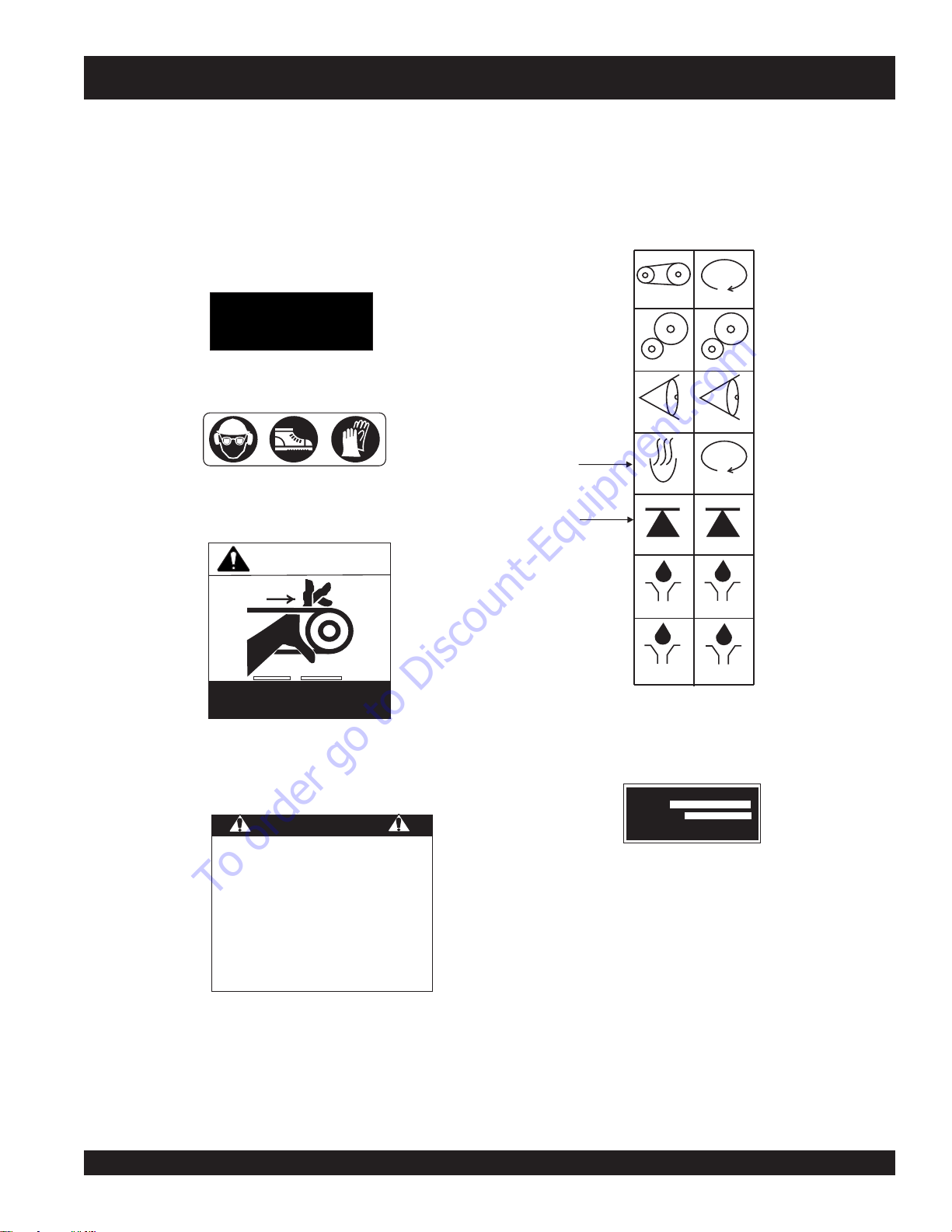
NEVER operate this equipment without proper protective
clothing, shatterproof glasses, steel-toed boots and other
protective devices required by the job.
The following safety guidelines should always be used when
operating the G-55H Gasoline Vibrator:
To order go to Discount-Equipment.com

PAGE 8 — G-55H GASOLINE VIBRATOR — OPERATION MANUAL — REV. #1 (07/08/21)
RULES FOR SAFE OPERATION
■
ALWAYS stop the engine before servicing, adding fuel
and oil.
■
NEVER run engine without air filter. Severe engine may
occur.
■
ALWAYS service air cleaner frequently to prevent
carburetor malfunction.
■
ALWAYS be sure the operator is familiar with proper
safety precautions and operations techniques before
using.
■
ALWAYS store equipment properly when it is not being
used. Equipment should be stored in a clean, dry location
out of the reach of children.
■
DO NOT operate this equipment unless all guards and
safety devices are attached and in place.
■
CAUTION must be exercised while servicing this
equipment. Rotating and moving parts can cause injury
if contacted.
■
Keep all
inexperienced
and
unauthorized
people away
from the equipment at all times.
■
Unauthorized equipment modifications will void all
warranties.
■
NEVER pour or spray water over the engine or electric
motor.
■
Test the
ON/OFF
switch for the gasoline engine before
operating.The purpose of these switches is to shut down
the engine of the vibrator.
■
Refer to the
HONDA Engine Owner's Manual
for engine
technical questions or information recommended by
Multiquip for this equipment. Damage to the equipment
and/or injury to user may result.
TRANSPORTING
■
ALWAYS shutdown engine before transporting.
■
Tighten fuel tank cap securely and close fuel cock to
prevent fuel from spilling.
■
ALWAYS use proper lifting techniques when using or
moving the vibrator motor, flexible shaft or vibrator head
assembly.
MAINTENANCE
■
NEVER lubricate components or attempt service on a
running vibrator.
■
ALWAYS allow the vibrator a proper amount of time to
cool before servicing.
■
Keep the vibrator in proper running condition.
■
Fix damage to the vibrator immediately and always
replace broken parts.
■
Dispose of hazardous waste properly. Examples of
potentially hazardous waste are used motor oil, fuel and
fuel filters.
■
DO NOT use food or plastic containers to dispose of
hazardous waste.
EMERGENCIES
■
ALWAYS know the location of the nearest
fire
extinguisher
and first aid kit.
■
In emergencies
always
know the location of
the nearest phone or
keep a phone on the
job site
. Also know the phone numbers of the
nearest
ambulance
,
doctor
and
fire
department
. This information will be
invaluable in the case of an emergency.
To order go to Discount-Equipment.com

G-55H GASOLINE VIBRATOR — OPERATION MANUAL — REV. #1 (07/08/21) — PAGE 9
Operation And Safety Decals
The MQ/STOW G-55H Gasoline Vibrator is equipped with a number of operation and safety decals (Figure 1).These decals
are provided for operator safety and maintenance information. Should any of these decals become unreadable, replacements
can be obtained from your dealer.
Figure 1. Operation and Safety Decals
OPERATION AND SAFETY DECALS
DECAL SHEET
INTL STDS ISO
P/N 11246
P/N 11247 (ISO Black)
P/N 21302
CONTACT PARTS
DEPARTMENT
P/N 36521
A
“HOT”
B
“LIFTING
POINT”
P/N 25883-001
CHECK
GEAR DRIVE
GEAR DRIVE
CHECK
HOT
BELT DRIVE CLOCKWISE
COUNTER
CLOCKWISE
LUBRICATION
LUBRICATION
LIFTING POINTLIFTING POINT
LUBRICATION
LUBRICATION
MODEL
SERIAL NO.
KEEP GUARDS
IN PLACE
WARNING!
READ THE OPERATING MANUAL BEFORE OPERATING
THIS MACHINE.
KEEP ALL UNAUTHORIZED AND UNTRAINED PEOPLE
AWAY FROM THIS MACHINE AT ALL TIMES.
ALWAYS DISCONNECT ENGINE SPARK PLUG WHEN
CLEANING, LUBRICATING, OR ADJUSTING THIS MACHINE.
NEVER LEAVE MACHINE RUNNING UNATTENDED
STOP THE ENGINE WHENEVER LEAVING THIS MACHINE.
DO NOT RUN VIBRATOR HEAD OUT OF
CONCRETE FOR OVER 5 MINUTES AT IDLE.
FAILURE TO COMPLY COULD
RESULT IN SERIOUS INJURY!
CAUTION
G-55H
To order go to Discount-Equipment.com

PAGE 10 — G-55H GASOLINE VIBRATOR — OPERATION MANUAL — REV. #1 (07/08/21)
General Information
The G-55H Gasoline Vibrator employs a 5.5 HP Honda engine.
It comes standard with a quick-disconnect coupling and an
eccentric belt tensioner.
The G-55H power unit utilizes a sturdy frame which enables
the engine to operate in a 360° rotation.
When operating the vibrator always wear rubber insulated
gloves and boots. Safety glasses are also recommended.
Tips
■
Keep the bending radius of the flexible hose to a minimum
during use.
■
Avoid starting the unit with the vibrator head immersed in the
concrete mix. After the engine has started, immerse the vibrator
head into concrete mix.
■
Excessive wear to the vibrating head can result from misuse.
DO NOT allow the head to vibrate against already hardened
concrete or steel used in reinforcement.
■
NEVER drop or knock the vibrator head against any hard
objects.This will prevent any damage the eccentric or bearings
contain within the head.
■
ALWAYS rinse or wipe off any wet concrete before it dries or
hardens on any part of the unit
(engine, shaft, or head).
GENERAL INFORMATION
Theory Of Concrete Vibration
The G-55H Vibrator is designed for the
compaction
of
concrete by removal of air pockets and voids.
The purpose of vibration is to set the particles in the fresh
concrete in motion, thereby reducing the friction between
the particles and giving the mixture the mobile quality of a
thick fluid so that gravity and the displacement of entrapped
air will cause it to settle easily into place.
By consolidating the concrete quickly, "stiffer" or "drier" mixes
can be poured than would otherwise be possible. It has
been proven that (up to a point) the drier the concrete, (that
is, the less water in it), the better the quality throughout and
the greater the strength. Drier mixes also make the concrete
more water tight, increase resistance to weathering, and
create a better bond between concrete and reinforcement.
Because vibration causes much of the entrapped air in the
concrete to rise to the surface, honeycombing is prevented.
Also, vibration eliminates most of the air pockets between
the concrete and the vertical forms.
Before operating this gasoline
powered vibrator, the operator
must
read
and
understand
the
contents of the operation manual.
Failure to read this manual could
result in severe bodily harm and
damage to the equipment.
To order go to Discount-Equipment.com

G-55H GASOLINE VIBRATOR — OPERATION MANUAL — REV. #1 (07/08/21) — PAGE 11
MAJOR COMPONENTS
Figure 2. G-55H Gasoline Vibrator Components
Figure 2 shows the location of the components and general
maintenance parts. The function of each component is
described below:
5. Rear Belt Guard – Attaches to the V-belt housing and
prevents access to the pulleys or V-belts while the vibrator
is running. DO NOT operate the vibrator with this cover
removed.
6. V-belt Housing – Encloses the pulley's and v-belts.
Access is provided through openings in the front and
rear of the housing.
7. Vibrator Support Stand – Allows the vibrator base to
sit upright. A pivot mechanism allows the base to freely
pivot in a complete 360 degree circle for operators
convieniance.
1. Eccentric Bell End – Supports the spindle shaft and
upper pulley which drives the vibration function of the
G-55H. The flexible shaft and quick disconnect are
inserted into the open end of the Eccentric Bell.
2. 328V Quick Disconnect – Connect the flexible shaft to
the quick disconnect and insert into the eccentric bell.
This allows for rapid removal of the flexible shaft end
from the vibrator base.
3. Quick Disconnect Lock Pin – Pull up on the lock pin
and pull the flexible shaft out to release the quick
disconnect from the eccentric bell. To insert a flexible
shaft, pull up on the lock pin and insert the quick
disconnect fitting. Release the pin and turn the fitting
until the lock pin drops into one of the holes on the fitting
end.
4. Front Belt Guard – Attaches to the V-belt housing and
prevents access to the pulleys or V-belts while the vibrator
is running. DO NOT operate the vibrator with this cover
To order go to Discount-Equipment.com

PAGE 12 — G-55H GASOLINE VIBRATOR — OPERATION MANUAL — REV. #1 (07/08/21)
Figure 3. Honda GX160T1QX2 Engine Components
5.5 HP Honda Gasoline Engine
The engine (Figure 3) must be checked for proper lubrication
and filled with fuel prior to operation. Refer to the
manufacturer's engine manual for instructions & details of
operation and servicing.The engine shown above is a HONDA
engine. Operation for other types of engines may vary.
1. Fuel Filler Cap – Remove this cap to add unleaded
gasoline to the fuel tank. Make sure cap is tightened
securely. DO NOT over fill.
ENGINE COMPONENTS
2. Throttle Lever – Used to adjust engine RPM speed
(lever advanced forward
SLOW
, lever back toward
operator
FAST
).
3. Engine ON/OFF Switch – ON position permits engine
starting,
OFF
position stops engine operation.
4. Recoil Starter (pull rope) – Manual-starting method.
Pull the starter grip until resistance is felt, then pull
briskly and smoothly.
5. Fuel Valve Lever – OPEN to let fuel flow, CLOSE to
stop the flow of fuel.
6. Choke Lever – Used in the starting of a cold engine, or
in cold weather conditions. The choke enriches the fuel
mixture.
7. Air Cleaner – Prevents dirt and other debris from entering
the fuel system. Remove wing-nut on top of air filter
cannister to gain access to filter element.
10. Fuel Tank – Holds unleaded gasoline. For additional
information refer to engine owner's manual.
11. Oil Drain Plug – Remove this plug to remove oil from
the engine's crankcase.
12. Dipstick/Oil Filler Cap – Remove this cap to determine
if the engine oil is low. Add oil through this filler port as
recommended in Table 3.
9. Muffler – Used to reduce noise and emissions.
Adding fuel to the tank should be done only when the
engine is stopped and has had an opportunity to cool
down. In the event of a fuel spill,
DO NOT attempt to start the engine until
the fuel residue has been completely
wiped up, and the area surrounding the
engine is dry.
DANGERDANGER
DANGERDANGER
DANGER
WARNINGWARNING
WARNINGWARNING
WARNING
Engine components can generate
extreme heat. To prevent burns, DO
NOT touch these areas while the engine
is running or immediately after
operating. NEVER operate the engine
with the muffler removed.
Explosive
Fuel Hazard
Burn Hazard
8. Spark Plug – Provides spark to the ignition system.
Clean spark plug once a week.
Operating the engine without an air filter, with a damaged
air filter, or a filter in need of replacement will allow dirt
to enter the engine, causing rapid engine wear.
NOTICE
To order go to Discount-Equipment.com

G-55H GASOLINE VIBRATOR — OPERATION MANUAL — REV. #1 (07/08/21) — PAGE 13
Figure 4. Engine Oil Dipstick (Removal)
Figure 5. Engine Oil Dipstick (Oil Level)
Engine Oil Check
1. To check the engine oil level, place the vibrator on
secure level ground with the engine stopped.
2. Remove the filler dipstick from the engine oil filler hole
(Figure 4) and wipe clean.
epyTliO.3elbaT
nosaeS erutarepmeT epyTliO
remmuS rehgiHroC°52 03-W01EAS
llaF/gnirpS C°01~C°52 02/03-W01EAS
retniW rewoLroC°0 01-W01EAS
LOWER LIMIT
INSPECTION
NEVER place hands or feet inside the belt
guard cover while the engine is running.
ALWAYS shut the engine down before
performing any kind of maintenance
service on the unit.
Inspection &
Maintenance Saftey
CAUTIONCAUTION
CAUTIONCAUTION
CAUTION
ALWAYS wear approved eye and
hearing protection before inspecting,
operating or servicing the vibrator.
CAUTIONCAUTION
CAUTIONCAUTION
CAUTION
Eyesight and Hearing
Protection
Before Starting
Before starting and operating the G55H Gasoline Vibrator,
perform the following:
■
Read safety instructions at the beginning of manual.
■
Clean the vibrator, removing dirt and dust, particularly
the engine cooling air inlet, carburetor and air cleaner.
■
Check the air filter for dirt and dust. If air filter is dirty,
replace air filter with a new one as required.
■
Check carburetor for external dirt and dust. Clean with
dry compressed air.
■
Check fastening nuts and bolts for tightness.
■
Check the engine oil level of the engine.
■
Check the fuel level of the engine.
■
Check the tension and condition of the vibrator power
unit's V-belts.
3. Insert and remove the dipstick without screwing it into
the filler neck. Check the oil level shown on the dipstick.
4. If the oil level is low (Figure 5), fill to the edge of the oil
filler hole with the recommended oil type (Table 3).
Maximum oil capacity is 0.63 quarts (.60 liters).
UPPER LIMIT
Reference manufacturer engine manual for specific
servicing instructions.
NOTICE
To order go to Discount-Equipment.com

PAGE 14 — G-55H GASOLINE VIBRATOR — OPERATION MANUAL — REV. #1 (07/08/21)
1. Remove the gasoline cap located on top of fuel tank.
2. Visually inspect to see if fuel level is low. If fuel is low,
replenish with unleaded fuel.
3. When refueling, be sure to use a strainer for filtration. DO
NOT top-off fuel. Wipe up any spilled fuel.
Gasoline is extremely flammable, and
its vapors can cause an explosion if
ignited. DO NOT start the engine near
spilled fuel or combustible fluids.
DO NOT fill the fuel tank while the engine is running or
hot. DO NOT overfill tank, since spilled fuel could ignite if
it comes into contact with hot engine parts or sparks from
the ignition system. Store fuel in approved containers, in
well-ventilated areas and away from sparks and flames.
Explosive Fuel Hazards
WARNINGWARNING
WARNINGWARNING
WARNING
INSPECTION
V-Belt Check
A worn or damaged V-belt can adversely affect the
performance of the vibrator.
1. Unscrew the bolts securing the front belt guard to the
belt housing
2. Inspect the belts for defects or wear.
3. If a V-belt is defective or worn, replace the V-belt as
outlined in the maintenance section of this manual.
Moving the Vibrator
Even though the vibrator is lightweight, always use two
people when lifting the vibrator or moving the unit around the
jobsite.
To order go to Discount-Equipment.com

G-55H GASOLINE VIBRATOR — OPERATION MANUAL — REV. #1 (07/08/21) — PAGE 15
6. Grasp the
recoil starter grip
(Figure 10) and slowly pull
it out. The resistance becomes the hardest at a certain
position, corresponding to the compression point. Pull
the starter grip briskly and smoothly for starting.
Figure 10. Starter Grip
3. Place the engine
choke lever
(Figure 8) in the CLOSED
position if starting a
cold
engine. Place the
choke lever
in the OPEN position if starting a
warm engine
or the
temperature is warm.
START-UP PROCEDURES
Starting the Engine
1. Place the engine
fuel valve lever
(Figure 6) to the ON
position.
2. Place the engine
throttle lever
(Figure 7) to the IDLE or
SLOW position.
Figure 6. Engine Fuel Valve Lever
Figure 7. Throttle Lever
Figure 8. Engine Choke Lever
5. Place the engine
ON/OFF switch
(Figure 9) in the ON
position.
Figure 9. Engine ON/OFF Switch
This section is intended to assist the operator
with initial start-up. It is extremely important
that this section be read carefully before
attempting to use the vibrator in the field.
DO NOT use your vibrator until this section is thoroughly
understood.
Failure to understand the operation of this vibrator could
result in
severe damage
to the vibrator or
personal injury
.
See Figures 2 and 3 for the location of any control
referenced in this manual.
WARNINGWARNING
WARNINGWARNING
WARNING
CAUTIONCAUTION
CAUTIONCAUTION
CAUTION
NEVER operate the vibrator in a
confined area or enclosed area structure
that does not provide ample
free flow
of air
.
General Safety
Respiratory Hazard
To order go to Discount-Equipment.com

PAGE 16 — G-55H GASOLINE VIBRATOR — OPERATION MANUAL — REV. #1 (07/08/21)
Figure 11. Engine ON/OFF Switch (OFF Position)
3. Close the
fuel shut- off valve
(Figure 12) by moving the
fuel valve lever to the OFF position.
Figure 12. Fuel Valve Lever (OFF Position)
Stopping The Engine
1. Move the throttle lever to the IDLE or SLOW position
(Figure 11) and run the engine for three minutes at low
speed.
2. After the engine cools, turn the engine
start/stop switch
to the OFF position (Figure 11).
7. If the engine has started, slowly return the choke lever
(Figure 6) to the OPEN position. If the engine has not
started repeat steps 1 through 6.
8. Before the vibrator is placed into operation, immerse the
vibrator head into the concrete and run the engine for
several minutes. Check for fuel leaks, and noises that
would associate with a loose V-belt cover or component.
START-UP/SHUTDOWN PROCEDURES
The vibrator head is cooled by the concrete. Operation
of the vibrator head in air longer than 2 minutes will
cause overheating of the bearings which result in
premature head failure.
CAUTIONCAUTION
CAUTIONCAUTION
CAUTION
Vibrator Head
Overheating Hazard
9. To begin use, move the throttle lever (Figure 6) toward the
FAST position.
To order go to Discount-Equipment.com

G-55H GASOLINE VIBRATOR — OPERATION MANUAL — REV. #1 (07/08/21) — PAGE 17
OPERATION
Operation
Read
all the safety instructions carefully. Safety instructions
will be found throughout this manual and on the vibrator motor.
Keep all safety information available, accessible, and in good,
readable condition.
■
Make certain that the flexible shaft is properly attached
to the motor and the head to the flexible shaft.
■
Use the flexible shaft in as straight a position as possible.
■
Do not bend the flexible shaft sharply at any point.
Sharp bends may cause a permanent kink, requiring
early replacement of the flexible shaft.
Connecting the vibrator head to the flexible shaft
1. Clean the mating parts threads with Loctite Primer “T”.
2. Allow to dry several minutes before applying a ring of
Loctite No.271 to the middle of the casing threads.
3. Screw the head tightly to the flexible shaft casing and
wait for 1 hour before using. The threads are left hand,
turn counter-clockwise to tighten. An equivalent brand
of anaerobic sealant may be used.
Figure 13. Couplings
The G55H Gasoline Vibrator, flexible shafting, and head are
shipped from the factory ready for assembly. Follow the
instructions listed below when connecting these parts before
using the gasoline vibrator.
Using head attachments not listed above may create a
hazardous condition when using the vibrator.
Equipment Combination Information
The following Equipment Combination Chart shows all of
the recommended connections between the gasoline vibrator
and the vibrator head.
SNOITANIBMOCTNEMPIUQE.5ELBAT
GNILPUOCTFAHSDAEH TFAHSXAM
HTGNEL
D.QV283V283
.biv0041 )mc3.231(.tf82
.biv0071
.biv0012)mc2.99(.tf12
WARNINGWARNING
WARNINGWARNING
WARNING
Equipment Hazard
Connecting the 382V Flexible Shaft
1. Connect the 382V Flexible Shaft to the Quick Disconnect
coupling (Figure 13).
2. Pull UP on the lock pin and slide the shaft and quick
disconnect assembly into the eccentric end bell and
release the lock pin.
3. Twist the shaft assembly to make sure that the lock pin
is seated in one of the 3 tapered holes on the quick
disconnect coupling.
To order go to Discount-Equipment.com

PAGE 18 — G-55H GASOLINE VIBRATOR — OPERATION MANUAL — REV. #1 (07/08/21)
OPERATION
Figure 14. Compaction Coverage
with 50% Radial Overlap
SNOISNEMID-PDNADAEH.4ELBAT
DAEH 004100710012
NOISNEMID-P .ni8
)mm4.13(
.ni21
).mm2.74(
.ni41
)mm1.55(
■
Immerse the head for 5 to 10 seconds, (until air stops
rising), and then withdraw it slowly to let the concrete fill
the void left by the vibrator head.
■
The vibrator head should be completely below the surface
when vibrating to keep the head cool.
■
When vibrating a thin horizontal slab, the vibrator head
can be used in a horizontal position.
Use the flexible shaft in as straight a position as possible
and do not bend the flexible shaft sharply at any point. Sharp
bends may cause a permanent kink, requiring early
replacement of the flexible shaft.
1. Start the engine as previously described and procede to
insert the vibrator head into the concrete.
2. The concrete is normally placed into the forms in layers
about 12 to 18 inches thick in a manner which forms a
fairly level surface. The vibrator head is inserted
vertically into the top of the pile.
3. When the surface has become fairly level, the vibrator
head then should be immersed and generally moved in
the pattern shown in (Figure 14).
If the shaft begins to helix (buckle) excessively during
operation, stop and investigate. This is an indication of an
overload condition.
CAUTIONCAUTION
CAUTIONCAUTION
CAUTION
Shaft Overload Hazard
The vibrator head is cooled by the concrete. Operation
of the vibrator head in air longer than 2 minutes will
cause overheating of the bearings which result in
premature head failure.
CAUTIONCAUTION
CAUTIONCAUTION
CAUTION
Vibrator Head
Overheating Hazard
DO NOT insert the vibrator head into the side of the
pile to make the concrete flow as this practice can
cause segregation of the aggregate from the mortar.
NOTICE
To order go to Discount-Equipment.com

G-55H GASOLINE VIBRATOR — OPERATION MANUAL — REV. #1 (07/08/21) — PAGE 19
Maintenance Instructions
To receive trouble-free service from your STOW G55H
gasoline vibrator, follow these instructions, as well as the
instructions contained in the engine operating manual,
flexible shaft operations manual and the vibrator head
operations manual.
The 382V flexible shafting requires cleaning and lubrication
every 100 hours of operation. Refer to the flexible shaft
operation and parts manual for maintenance instructions.
Vibrator heads should be inspected and relubricated every
100 hours of operation.Refer to the vibrator head operation
and parts manual for maintenance instructions.
MAINTENANCE
Whenever assembling, lubricating, or adjusting any part
of the gasoline vibrator make certain to stop the engine,
disconnect the spark plug wire and secure it away from
the spark plug.
WARNINGWARNING
WARNINGWARNING
WARNING
Disabling the Engine
for Maintenance
Daily
■
Thoroughly remove dirt and oil from the engine and
control area. Clean or replace the air cleaner elements
as necessary. Check and retighten all fasteners as
necessary. Check the gearbox for oil leaks. Repair or
replace as needed.
Weekly
■
Remove the fuel filter cap and clean the inside of the
fuel tank.
■
Remove or clean the filter at the bottom of the tank.
Engine Oil
1. Drain the engine oil when the oil is
warm
as shown in
Figure 25.
2. Remove the oil drain bolt and sealing washer and allow
the oil to drain into a suitable container.
3. Replace engine oil with recommended type oil as listed
in Table 3. For engine oil capacity, see Table 2 (engine
specifications). DO NOT overfill.
4. Install drain bolt with sealing washer and tighten securely.
Figure 15. Spark Plug Gap
Figure 16. Engine Oil (Draining)
Used oil can generally be taken to your local recycling center
or service station for reclamation. Follow all required
environmental rules and regulations required in your area
concerning the disposal of hazardous waste such as used
oil and oil filters.
■
Remove and clean the spark plug (Figure 24), then adjust
the spark gap to 0.024 ~0.028 inch (0.6~0.7 mm). This
unit has electronic ignition, which requires no
adjustments.
NOTICE
Dispose of used oil properly. DO NOT pour used oil on
the ground, down a drain, or throw in the trash.
Heat should be used to break down the loctite while you
unthread the head from the shaft.This will prevent possible
damage to the threads from the loctite.
NOTICE
To order go to Discount-Equipment.com
Table of contents
Other MULTIQUIP Industrial Equipment manuals