MX MX R10 User manual

FRONT LINKAGE
MX R10
MX R16
User manual
Please read carefully before using MX
front linkage
UK 361905 AG -0919
Translation of the original manual


Dear users,
Thanks you for condence in our product. We are sure it will give you full satisfaction.
By taking a few minutes to read this manual, you will be able to obtain the best results from your MX front linkage,
extend its lifespan and work in complete safety.
The front linkage user manual is a very important document, please keep it with you in order to be able to use it if
required. Leave it available to any other user and give it to the next owner of this front linkage.
Pictures and technical information included in this document may not correspond precisely to your front linkage;
but the working conditions will be the same.


CONTENTS
1. SAFETY REGULATIONS 6
2. USAGE REGULATION 7
3. SAFETY STICKERS 8
4. IDENTIFICATION PLATE 8
5. DESCRIPTION 9
6. OPERATING POSITION 10
7. IMPLEMENT HITCHING 12
8. IMPLEMENT DISCONNECTING 13
9. FOLDED ARMS POSITION 14
10. REAR SUPPORT* 15
11. PUSH BAR* 15
12. SHOCK ELIMINATOR* 16
13. FRONT POWER TAKE OFF (PTO)* 16
14. ADDITIONAL FRONT HYDRAULIC LINE* 17
15. 3-WAY SELECTOR* 18
16. EXTERNAL CONTROL* 19
17. ACCESSORIES 19
18. CONTROL 20
19. MAINTENANCE 21
20. TECHNICAL SPECIFICATIONS 22
* According to equipment


5 Modication reserved
• 19, rue de Rennes • BP 83221 • F - 35690 ACIGNÉ
The operator must read this manual before using
theproductforthersttime.
Familiarise yourself with:
— Safety and operating regulations.
— Hitching and unhitching of the implement.
— Full use of the controls.

6 Modication reserved
• 19, rue de Rennes • BP 83221 • F - 35690 ACIGNÉ
1. SAFETY REGULATIONS
— The tractor/loader/linkage assembly must only be driven by someone who is trained and experienced.
— When the tractor is tted with a front linkage and loader, the user has to unhitch the loader before to using the MX front linkage (please see the loader
instruction book for the unhitching proceedure).
— CAUTION: before using of the front loader, please check the front linkage is locked (with the hydraulic tap), and the arms are folded or removed (see chapter
"folded arms position").
— Control the front linkage only from the driver’s seat, or from the external remote control supplied by MX. Do not let go of the controls until the movements
are complete.
— The controls for operating the front linkage must be of the "continued action" type with the exception of the lift oating position which can be maintained
in its position by a notching system.
— Do not leave the seat before locking the controls to prevent any movement.
— It is compulsory to ensure that nobody is in the area while the front linkage and tractor are in use.
— The transport or elevation of persons using the front linkage is forbidden..
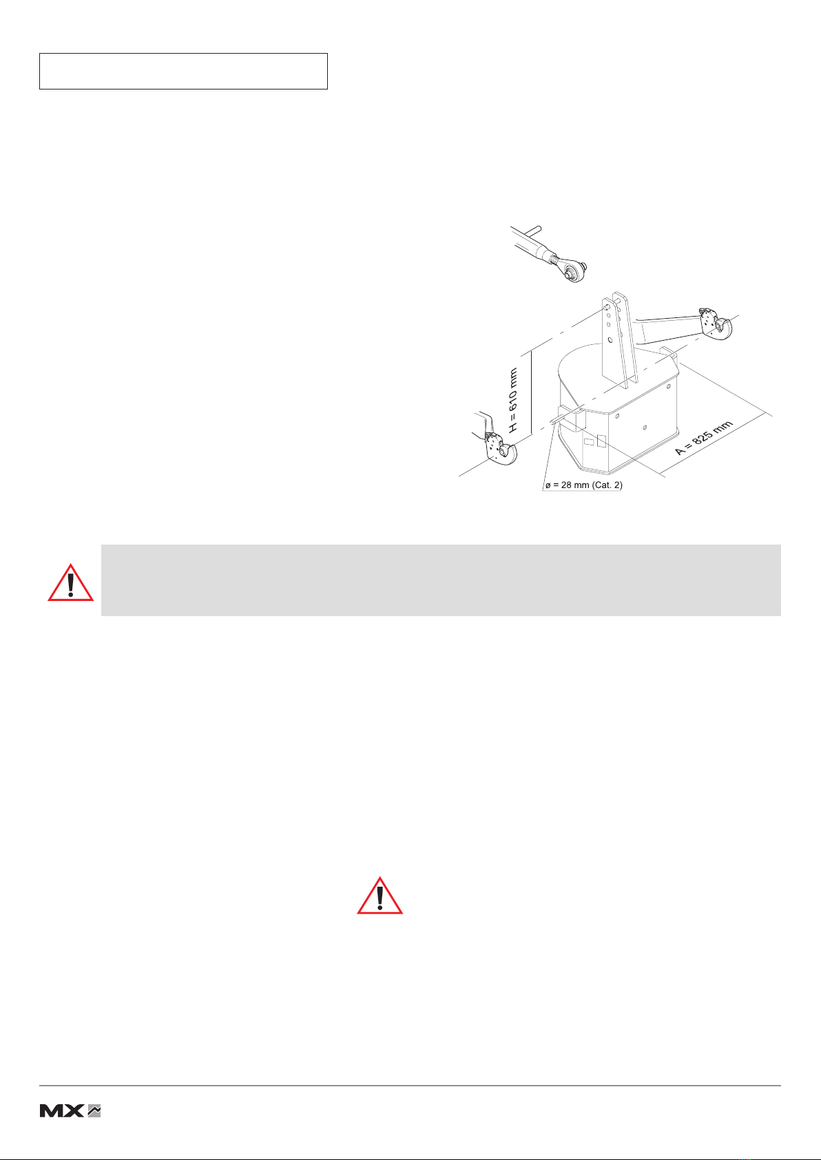
— Before moving with a front implement tted, check and ensure that the tractor-front implement assembly is stable by tting a counter weight at the rear of
the tractor. This should provide 20% of the gross weight (tractor-front implement) on the rear axle of the tractor for driving and working in the best
safety conditions.
— The maximum front axle safe load provided by the tractor’s manufacturer must not be exceeded.
— The front tyres maximum safe load provided by the tyres’s manufacturer must not be exceeded.
— Check regularly tyres pressure.
— An implement hitched to the front linkage must be able to be lifted through the full range of linkage’s movement. Any excess load preventing this movement
is strictly forbidden.
— Before moving, the user must ensure that the front linkage is in good working order and can be used safely.
— When driving on the road with a front implement, the front linkage must always be in a raised position and the road regulations must be respected
(dimensions, signalling on implement, etc.).
— When driving on the road without a front implement, the front linkage must be set to the transport position (see section "Setting the front linkage to transport
position").
— Whenever the tractor is stopped for a short or long time, the engine must be switched off and the linkage lowered.
— The tractor must never be towed from an anchoring point on the front linkage.
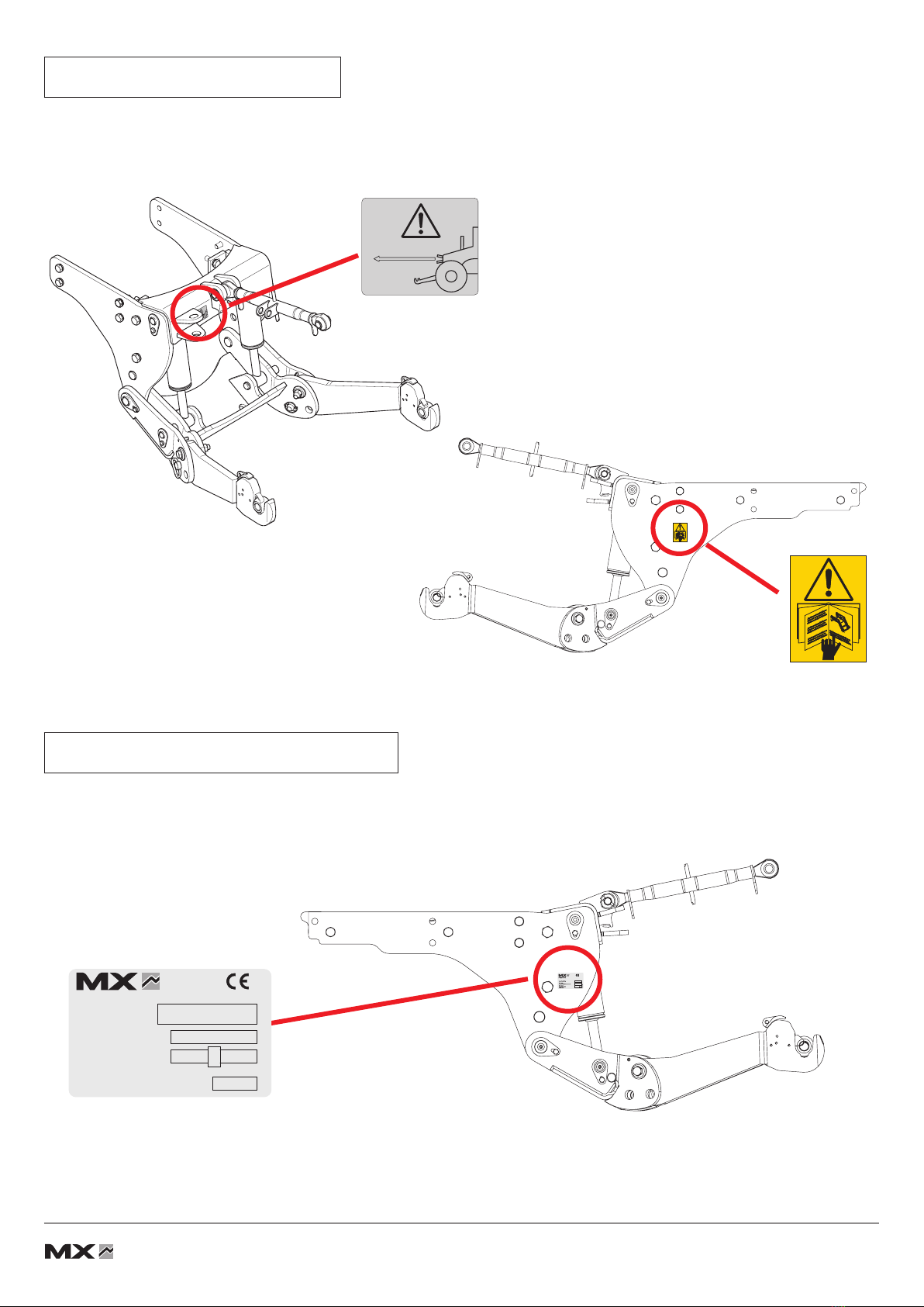
— Regularly check the presence of safety pins and bolts. Do not replace with any other object such as nails, wire, etc.
— Any activity relating to defect investigation (diagnosis) and / or disassembly of parts may only be undertaken by an accredited professional who shall
assure his safety and the protection of the environment in which the actvity is conducted.
Caution!
— The front linkage’s hydraulic circuit is designed to have a maximum service pressure of 200 bar.
— Never modify the hose connections
— The assembly of an MX front linkage which excludes the recommendations in the MX price list in force at the purchase date, cancels the MX guarantee
on all the equipment supplied.
— Any modication to a section of any MX equipment (rams, arms, pivot frame, etc.) or the use of an implement or element installed on the MX front linkage
from foreign origin, cancels the MX guarantee for all equipment supplied.
— Use only MX original spare parts. Do not modify your MX Front linkage yourself or have another person modify them, without prior written agreement from
MX. Failure to respect these regulations may make the Front linkage dangerous. MX will disclaim all responsibility in the event of damage or injury.
— The guarantee is immediately invalid when the instructions for use, and the MX Front linkage maintenance schedule outlined in the "User Manual" are
not observed.

7 Modication reserved
• 19, rue de Rennes • BP 83221 • F - 35690 ACIGNÉ
2. USAGE REGULATION
2.1
The front linkage is designed for implements which comply with the hitching dimensions dened in standard
ISO 8759-1
for
category
II.
The distance of the implement’s hitch points must be
825 mm (dimension A) with a linkage pin of 28 mm
diameter.
The vertical height of the implement must be 610 mm
(dimension H).
2.2 Implement/link point distance and ground work.
The hitched implement must be xed as close as possible to the hook-up points on the front linkage. In actual fact, the greater
the front overhang, the higher the stresses on the front linkage (leverage). The more compact the implement xing, the less
strain there is on the equipment. Use of a compact implement also improves the lifting performances.
For pushing work (implements of the soil decompaction or dozer blade type for instance), it is strongly recommended that
a push bar be tted to reinforce the tractor from the front linkage to the rear trumpet housings.
Caution!
Recommendations for xing the implement, and working on the ground, must be strictly complied with. Any deviation
from the requirements described above may cause serious damage, for which MX cannot be held liable.
Hitching an implement on which dimension ‘H’ is less than that shown places excess strain on the top link and may
damage it.
Hitching an implement with a dimension greater than H can damage the front of the tractor (bonnet, front guard,
etc.) during the lifting operation.

3T Maxi
19, rue de Rennes F - 35690 ACIGNÉ
Type / Model / Typ
N˚ de série
Serial number
Seriennummer
Poids à vide
Unloaded weight / Leergewicht kg
328462
Désignation/
Designation
Année / Year
8 Modication reserved
• 19, rue de Rennes • BP 83221 • F - 35690 ACIGNÉ
3. SAFETY STICKERS
Safety stickers are located on the front linkage. Keep them readable and clean, and change them if damaged.
4. IDENTIFICATION PLATE
The identication plate is located on the right hand side of the headstock.
The serial number and front linkage type which are indicated on this plate might be requested when requiring spare parts
or technical assistance.

3
4
9
1
12
11
2
7
6
5
108
9 Modication reserved
• 19, rue de Rennes • BP 83221 • F - 35690 ACIGNÉ
5. DESCRIPTION
1: Right arm
2: Left arm
3: Arm pin
4: Linkage frame
5: Top-link yoke
6: Top-link bar
7: Lever locknut
8: Hitch yoke (use a 30 mm diameter pin)
9: Ram
10: Frame
11: Coupler
12: Ball end

10 Modication reserved
• 19, rue de Rennes • BP 83221 • F - 35690 ACIGNÉ
6. OPERATING POSITION
6.1 Choose a at and stable area.
Pull the parking brake. Turn off the engine.
6.2 Leave the cab and remove the L.H. arm locking pin.
6.3 Support the L.H. arm and remove the pin.
Caution
This operation must be carried out by the driver who must leave the seat and
ensureallmanoevresareforbiddenwhileheisworkingonthefrontlinkage.

Fermé Ouvert
11 Modication reserved
• 19, rue de Rennes • BP 83221 • F - 35690 ACIGNÉ
6.4 Swing the arms forwards to the desired position.
Position 1: Fixed position.
Position 2: Floating position.
Arm in oating position. The implement follows the contours of
the ground.
6.5 Put the pin back in position, and lock with the locking pin.
6.6 Repeat the items 6.2 à 6.5 for the right arm.
6.7 Open the stop valve.
Closed Open

12 Modication reserved
• 19, rue de Rennes • BP 83221 • F - 35690 ACIGNÉ
7. IMPLEMENT HITCHING
The linkage is in working position.
7.1 Open the locking catches on the hitching hooks and hitch up
the implement.
Check that the implement is tted with suitable coupling balls
secured with locking pins.
7.2 Hitch the top link bar to the mast of the front implement.
7.3 Set the length of the top link bar to obtain the required movements
from the front implement.
Lock the adjustment of the bar by means of the lever locknut.
Checking before work
— Test the lifting by checking that the tractor/front implement combination works correctly. Particularly check the space
between the top link bar and the tractor’s engine bonnet.
— Check that all the pins and locking pins are tted and locked correctly.
— Check the locking status of the hitching hooks (the catches must be retracted correctly).
Caution
This operation must be carried out by the driver who must leave the seat and
ensure all manoevres are forbidden while he is working on the front linkage
.

13 Modication reserved
• 19, rue de Rennes • BP 83221 • F - 35690 ACIGNÉ
8. IMPLEMENT DISCONNECTING
8.1 Lay the implement on some at stable ground. Operate
the tractor’s handbrake.
8.2 Free the top link bar from the mast of the front implement.
8.3 Reposition the upper link bar on to the front linkage frame.
8.4 Unlock the hitching hooks and lower the linkage arms to release
the implement.
Caution
This operation must be carried out by the driver who must leave the seat and
ensure all manoevres are forbidden while he is working on the front linkage
.

Fermé Ouvert
14 Modication reserved
• 19, rue de Rennes • BP 83221 • F - 35690 ACIGNÉ
9. FOLDED ARMS POSITION
9.1 Choose a at and stable area. Raise the front linkage arms.
Apply the parking brake and shut off the engine.
9.2 Close the stop valve.
9.3 Hold the R.H. arm and remove the pin.
Caution
This operation must be carried out by the driver who must leave the seat and
ensure all manoevres are forbidden while he is working on the front linkage
.
Closed Open

15 Modication reserved
• 19, rue de Rennes • BP 83221 • F - 35690 ACIGNÉ
9.4 Swivel the arm towards the bac and put the pin and the locking
pin back in position.
9.5 Repeat the items 9.3 et 9.4 for the left arm.
10. REAR SUPPORT*
This structure is located under the tractor and it
reinforces the tractor from the clutch bell housing
to the rear trumpet housings.
11.PUSH BAR*
This attachment is located under the tractor,
providing it withoverall reinforcement from the front
linkage to the rear trumpet housings.
This equipment is strongly
recommended for any heavy
pushing work (e.g.: plough, soil
decompaction implement, dozer
blade,etc.).
* According to equipment

β
α
Leergewicht
16 Modication reserved
• 19, rue de Rennes • BP 83221 • F - 35690 ACIGNÉ
12. SHOCK ELIMINATOR*
The shock absorber function requires that:
— The minimum load for Shock Eliminator efciency corresponds to
20% of the linkage max. capacity.
NOTE: The greater the load, the smaller the shock absorber travel
must be.
— The linkage is never at its maximum height. To attain the shock-
absorbed transport position, the linkage must be lowered slightly
starting from the upper position.
13. FRONTPOWERTAKEOFF(PTO)*
SAFETY REGULATIONS AND RECOMMENDATIONS REGARDING THE FRONT PTO
— Never start the engine with the power take-off engaged.
— Before hitching the implement, check that the implement’s direction
of rotation is compatible with the front power take-off.
— Check to ensure that the speed and power rating of the implement are
matched to the power take-off. Otherwise, the implement must not be
hitched and connected (refer to the section "Technical specications").
— Do not use a high inertial load implement without a PTO overrun clutch.
— Check and adapt the length of the transmission shaft between
the implement and the front power take-off.
— The universal joint of the transmission shaft must be tted with
suitable protection (complying with the standard ISO/DIS 5673-1).
— Never lift or lower the front linkage with the power take-off under load.
— Check the a and ß angles of the implement’s universal joint and
the power take-off. Adjust the length of the top link to make these
angles approximately equal (see diagram opposite). The limit value
of the a and ß angles depends on the type of universal joint used (refer to the universal joint manufacturer’s user manual).
— The engine must be stopped for any maintenance on the implement for which hydraulic must be locked.
— Each time the power take-off is used, grease the sliding section of the shaft and the universal joint spiders beforehand.
— Never make any changes to the electrical connections.
— Observe the maintenance instructions (refer to the section "Maintenance").
— The safety instructions in this manual are not to be construed as a replacement for safety regulations, insurance requirements
or national and local legislation. Ensure your machine is tted with the correct equipment as required by law and local
regulations.
* According to equipment

17 Modication reserved
• 19, rue de Rennes • BP 83221 • F - 35690 ACIGNÉ
13.1 Hitch up the implement (refer to the section "Hitching a front
implement" in this manual).
13.2 Connect the PTO shaft to the front power take-off.
The engine must be stopped.
13.3 The power take-off is engaged and disengaged by pressing
the switch located in the cab.
The engine speed must never exceed 1200 rpm when
starting up the power take-off.
13.4 Increase engine speed to 2100 rpm in order to attain
the rotational speed required by the implement (i.e. 1000 rpm).
13.5 After using the power take-off, disengage it using the same
switch located in the cab.
14. ADDITIONAL FRONT HYDRAULIC LINE*
This supplies a hydraulic unit in front of the linkage.
14.1 Connect the hydraulic hoses of the implement to the 1/2" female
couplings. Release the pressure in the hydraulic system to
make connecting the hoses easier.
14.2 Control the hydraulic line using the tractor’s control valve
or the MX control valve (refer to the "control" section).
* According to equipment
Caution
This operation must be carried out by the driver who must leave the seat and
avensure all manoevres are forbidden while he is working on the front linkage
.
Checking before work
— Check that the tractor, implement and transmission shaft interact correctly throughout the full lifting stroke before engaging
the power take-off.

18 Modication reserved
• 19, rue de Rennes • BP 83221 • F - 35690 ACIGNÉ
15. 3-WAY SELECTOR*
This selector, which is located behind the cab, enables the front linkage operating mode to be selected to suit your
application with a single movement.
There are 3 operating modes:
15.1 "Locking" operation.
Usage: this mode is used when the MX front linkage is not being
used or for travelling long distances with an implement
or a weight (safety in transit).
Plus, it enables the couplings at the rear of the tractor to be freed
up for another powered implement.
Description: the MX front linkage hydraulic system is locked
out. The linkage arms can no longer be raised or lowered.
Do the following: turn the levers as shown in the photo opposite.
15.2 "Double-acting" operation.
Usage: this mode is used mainly when hitching up an implement
(lowering linkage arms) and for working the soil with a bulldozer
blade for instance.
Description: the rams on the MX front linkage are pressurised
on both lifting and lowering.
Do the following: turn the levers as shown in the photo opposite.
15.3 "Single-acting" operation.
Usage: this mode is used mainly with a front-end mowers
or with an implement tted with depth wheels.
Description: the rams on the MX front linkage are pressurised
on lifting, but lowering takes place through gravity (unpressurised)
due to the weight of the implement. This absence of pressure
on lowering ensures the implement rests unconstrained on
the ground. This protects the implement.
Do the following: turn the levers as shown in the photo opposite.
* According to equipment
Caution
— The levers must always be turned fully to either stop.
— Switching from Single-acting to Double-acting operation (and vice versa) must not be carried out before releasing
the hydraulic pressure.
This manual suits for next models
6
Table of contents
Popular Industrial Equipment manuals by other brands

Blue Ox
Blue Ox BedSaver BXR5000 Operator and installation manual

EMUGE
EMUGE Speedsynchro Modular/NFC Operating instruction

WMH Tool Group
WMH Tool Group JET JCP Series owner's manual

GRESSEL
GRESSEL S2 Installation and operating instructions

Texas Automation Products
Texas Automation Products HM-32 quick start guide

socomec
socomec MDO 1600 TS USE AND MAINTENACE MANUAL