MULTISOFT DGR-1000 User manual

VIDEO GRABBER
DGR-1000
User Manual
v. 1.4 (FW 1.9)

Video Grabber DGR-1000 User Manual - v. 1.4 (FW 1.9)
2
Disclaimer
§1
The manufacturer is not responsible for any device defects resulting from non-compliance with the
device manual and its purpose.
§2
This product has been designed for the specific use. This product cannot be used for other purposes,
including illegal ones
§3
It is the buyer's responsibility to check whether a particular product with the properties described in
the manual is suitable for use in a specific case
§4
The manufacturer reserves the right to update the information contained in the device's instruction
manual - the current manual can be obtained after contacting technical support via e-mail:
support@multisoftsa.com
§5
If the warranty for the device is given, it does not apply to the Software or Hardware which has not
been installed, operated, repaired, or maintained in accordance with device manual.
§6
To the extent permitted by law, neither manufacturer nor any of its employees, will not be liable in
any way for any loss, damage, lost benefits, cost or expenses suffered by buyer, associated with
improper use of the device
§7
Manufacturer does not grant, explicitly or implicitly, to purchasers of the device any patent rights,
licenses, or any other Intellectual Property rights, unless it is reserved in a separate written
agreement
§8
The buyer cannot copy, distribute, transmit, display, perform, reproduce, publish, license, create
derivative works, transfer or sell any information about device and it’s documentation without
concluding a separate written agreement with manufacturer

Video Grabber DGR-1000 User Manual - v. 1.4 (FW 1.9)
3
Table of contents
1. General description......................................................................................................5
2. Device overview...........................................................................................................6
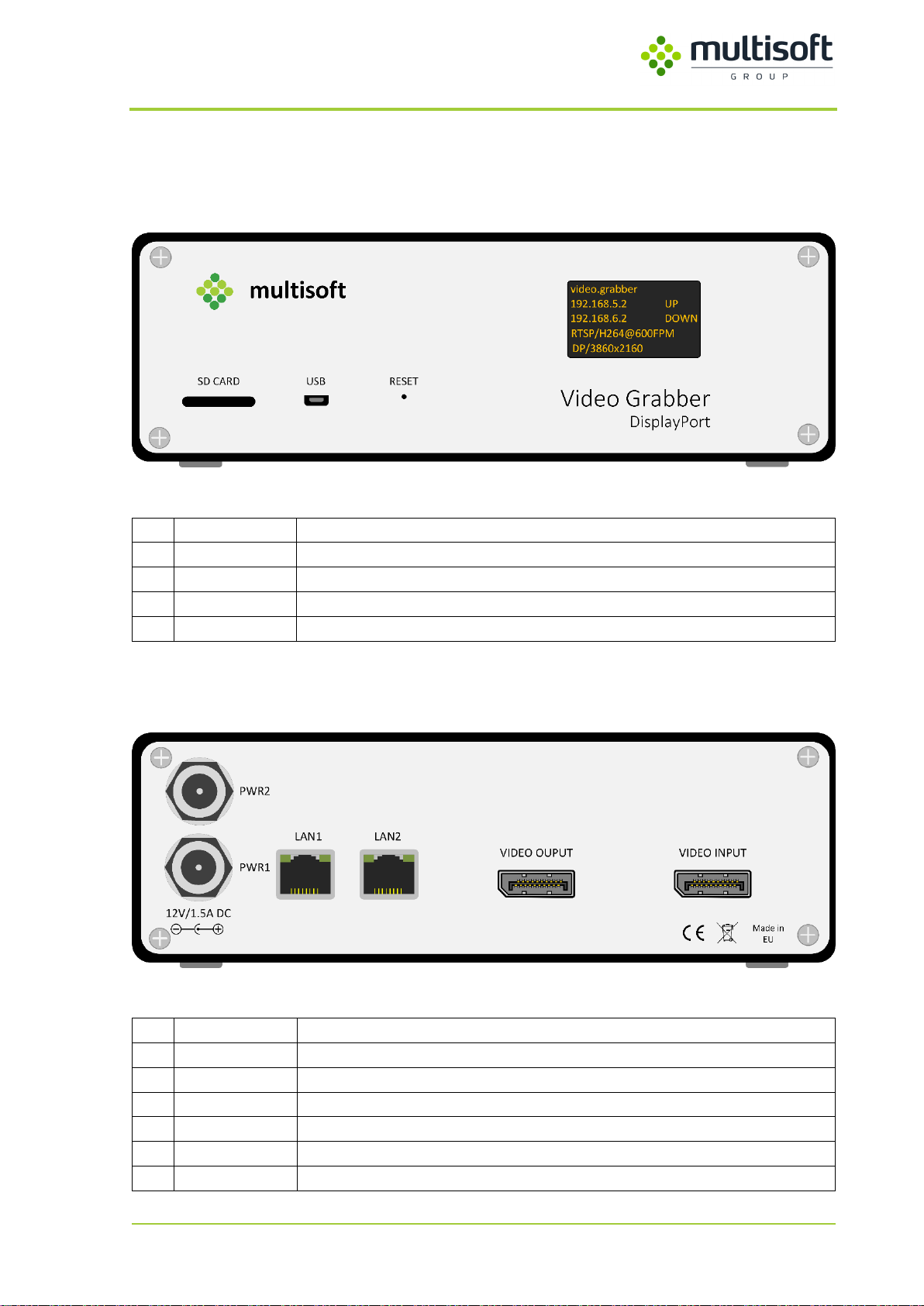
2.1. Front panel...................................................................................................................6
2.2. Back panel....................................................................................................................6
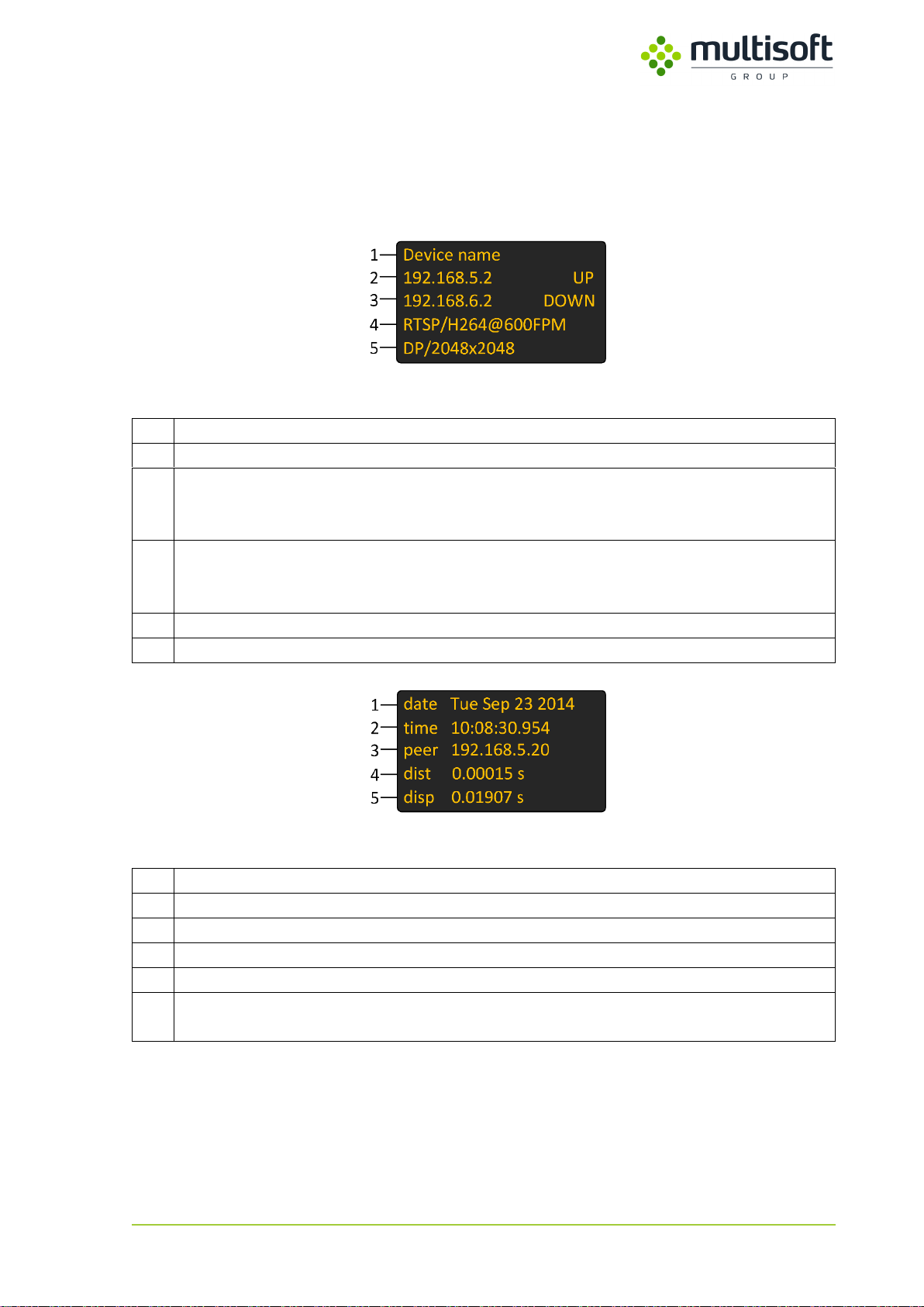
2.3. OLED screen.................................................................................................................7
3. Device installation........................................................................................................8
3.1. Introduction .................................................................................................................8
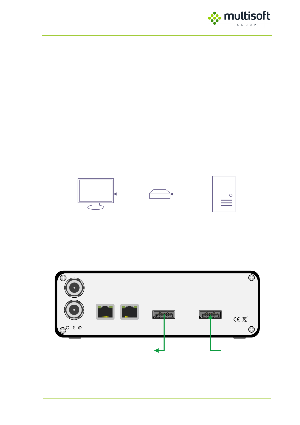
3.2. Pass-through ................................................................................................................8
3.3. Monitor emulation.......................................................................................................9
3.4. Resolution support.....................................................................................................10
3.5. Network connection ..................................................................................................11
3.6. Power supply unit ......................................................................................................12
4. Video Grabber Web Interface....................................................................................13
4.1. Status page.................................................................................................................14
4.1.1. Device status ..........................................................................................................15
4.1.2. Power .....................................................................................................................16
4.1.3. Network..................................................................................................................17
4.1.4. Video ......................................................................................................................18
4.1.5. NTP .........................................................................................................................22
4.2. Configuration page ....................................................................................................24
4.2.1. General...................................................................................................................26
4.2.2. Network..................................................................................................................27
4.2.3. Video ......................................................................................................................29
4.2.4. NTP .........................................................................................................................42
4.2.5. Commands..............................................................................................................43
4.3. Preview & Adjust page...............................................................................................44
4.3.1. Preview...................................................................................................................45
4.3.2. Monitor emulation.................................................................................................46
4.3.3. EDID........................................................................................................................47
4.4. Administration ...........................................................................................................48
4.4.1. Status reporting......................................................................................................49
4.4.2. WWW access..........................................................................................................50
4.4.3. SNMP access...........................................................................................................51
4.4.4. Commands..............................................................................................................52
5. SNMP..........................................................................................................................53
5.1. Introduction ...............................................................................................................53
5.2. Accessing the Video Grabber via SNMP ....................................................................53
5.2.1. Read-only user........................................................................................................54
5.2.2. Read-write user......................................................................................................55

Video Grabber DGR-1000 User Manual - v. 1.4 (FW 1.9)
4
5.3. Information (section 1)..............................................................................................56
5.4. Status (section 2) .......................................................................................................57
5.4.1. staVersion (subsection 1).......................................................................................57
5.4.2. staGeneral (subsection 2) ......................................................................................58
5.4.3. staVideo (subsection 3)..........................................................................................59
5.4.4. staNtp (subsection 4) .............................................................................................61
5.4.5. staRtsp (subsection 5) ............................................................................................63
5.4.6. staFs (subsection 6)................................................................................................64
5.5. Configuration (section 3) ...........................................................................................65
5.5.1. confVersion (subsection 1).....................................................................................65
5.5.2. confOutput (subsection 2) .....................................................................................66
5.5.3. confCodec (subsection 3).......................................................................................67
5.5.4. confControl (subsection 4).....................................................................................69
5.5.5. confLan (subsection 5) ...........................................................................................70
5.5.6. confNfs (subsection 6)............................................................................................72
5.5.7. confSmb (subsection 7)..........................................................................................73
5.5.8. confNtp (subsection 8)...........................................................................................75
5.5.9. confEdid (subsection 9)..........................................................................................76
5.5.10. confUpdate (subsection 11)...................................................................................77
5.5.11. confDpVideo (subsection 12).................................................................................78
6. Firmware upgrade......................................................................................................79
6.1. Introduction ...............................................................................................................79
6.2. microSD card / USB pendrive.....................................................................................79
6.3. TFTP server.................................................................................................................80
7. Factory reset ..............................................................................................................81
Appendix A: Status UDP frame structure.................................................................................82
Appendix B: Broadcast UDP packet structure..........................................................................83

Video Grabber DGR-1000 User Manual - v. 1.4 (FW 1.9)
5
1. General description
Video Grabber DisplayPort (DGR-1000) is a real-time video capturing device that works using the
DisplayPort 1.2 interface. Equipped with a passive video splitter it can be safely installed between the
computer and its screen (Pass-through connection –See 3.2, p. 8) as it doesn’t even have to be
powered on to forward the video signal to the display
1
. In cases where absolutely no interference in
the recorded signal is allowed DGR-1000 can even emulate a specific monitor and record a mirrored
video signal thus ensuring that the link between video source and the display remains untouched
(Monitor emulation –See 3.3, p. 9).
Configured either using web browser or via SNMPv3 DGR-1000 provides wide variety of possibilities:
both lossless and lossy compression algorithms are available, captured signal can be provided as RTSP
stream or saved at a user-defined network location. Support for Network Time Protocol (NTP) makes
it possible to timestamp the data at the moment of its capture.
Designed for the Air Traffic Control, DGR-1000 provides an option for power and network
redundancy.
1
Integrated video splitter requires at least 500mA on pin 20 of DisplayPort port for passive mode. It can be
provided by the monitor or graphics card (or both)

Video Grabber DGR-1000 User Manual - v. 1.4 (FW 1.9)
6
2. Device overview
2.1. Front panel
Figure 1: Front panel of the Video Grabber DGR-1000
No.
Name
Description
1
SD Card
Used for firmware update and factory reset
2
USB
Used for firmware update and diagnostics
3
Reset
Used to reboot the device
4
OLED screen
Displays Video Grabber’s runtime information
2.2. Back panel
Figure 2: Back panel of the Video Grabber DGR-1000
No.
Name
Description
1
PWR1
Primary power connector
2
PWR2
Secondary power connector
3
LAN1
Frist network interface
4
LAN2
Second network interface
5
VIDEO OUTPUT
DisplayPort, output signal
6
VIDEO INPUT
DisplayPort, input signal

Video Grabber DGR-1000 User Manual - v. 1.4 (FW 1.9)
7
2.3. OLED screen
By default OLED screen displays basic status information of the device. User can configure it to also
show a view with NTP status. In such case both ‘views’ are shown at intervals (See 4.2.1 on p. 26 for
details on OLED configuration.
Figure 3: Device status screen
No.
Description
1
Configurable device name
2
IP address set on the first network interface (LAN1) along with the link status:
UP –link is active
DOWN –link is inactive
3
IP address set on the second network interface (LAN2) along with the link status:
UP –link is active
DOWN –link is inactive
4
Currently used Output settings displayed in format: protocol / format @ capture frequency
5
Parameters of signal connected to the device displayed in format: signal type / resolution
Figure 4: NTP status screen
No.
Description
1
Current date set on the Video Grabber
2
Current time set on the Video Grabber
3
IP address of currently used NTP server
4
Root distance to the currently used NTP server
5
Dispersion –potential clock offset error due to the maximum uncorrected system clock
frequency error

Video Grabber DGR-1000 User Manual - v. 1.4 (FW 1.9)
8
3. Device installation
3.1. Introduction
Video Grabber DGR-1000 is designed to capture and process video signal from DisplayPort 1.2
interface. While by default it is assumed that DGR-1000 is installed between the computer and its
monitor –pass-through –it can also be installed independently as an emulated monitor. See the
following sections for instructions on both approaches.
Regardless of the approach chosen it is advised to turn off all equipment involved in cable
connections (display, recorded computer and Video Grabber) for the time of the installation.
3.2. Pass-through
By default Video Grabber captures the video data that is sent by the computer to the display. It is
connected between those two devices (see figure below).
ComputerMonitor
DGR-1000
Figure 5: Pass-through connection schema
Computer is connected to the DGR-1000’s video input port, and the monitor is connected to the Video
Grabber’s video output port. As a result Video Grabber effectively captures the video signal that is
being sent by the computer to the monitor.
12V/1.5A DC
LAN 1
Made in EU
LAN 2
VIDEOOUTPUT VIDEOINPUT
PWR1
PWR2
ComputerMonitor
Figure 6: Video cable connections required for pass-through
It is advised to use the same types of cables for input and output

Video Grabber DGR-1000 User Manual - v. 1.4 (FW 1.9)
9
3.3. Monitor emulation
Computer sends the same video signal on two of its video ports. One is connected to the monitor and
the other is connected to the Video Grabber. See the connection details below.
ComputerMonitor DGR-1000
Mirrored
outputs
Figure 7: Monitor emulation connection schema
One of the computer’s video outputs is connected to the DGR-1000’s video input port while the other
is connected to the monitor. When ‘Monitor emulation’ is enabled in the Video Grabber’s
configuration it is detected by the computer as a monitor and as such can be configured as a mirror of
an actual screen in the computer’s graphic card configuration.
12V/1.5A DC
LAN 1
Made in EU
LAN 2
VIDEOOUTPUT VIDEOINPUT
PWR1
PWR2
Computer
Figure 8: Video cable connection required for the monitor emulation

Video Grabber DGR-1000 User Manual - v. 1.4 (FW 1.9)
10
3.4. Resolution support
Video Grabber has been tested with various screen resolutions. See the list of supported (tested and
verified to work) monitor resolutions in tables below. Resolutions that are not on the list may still work,
but they have not been tested.
Supported resolutions
320 x 240
1152 x 846
1400 x 1050
1920 x 1440
2560 x 2048
480 x 320
1176 x 664
1440 x 900
2048 x 1024
3072 x 1536
640 x 480
1200 x 960
1600 x 900
2048 x 1080
3072 x 1728
720 x 480
1280 x 720
1600 x 1024
2048 x 1152
3840 x 1600
720 x 576
1280 x 768
1600 x 1200
2048 x 1536
3840 x 2160
800 x 480
1280 x 800
1680 x 1050
2048 x 2048
800 x 600
1280 x 960
1768 x 992
2560 x 1080
1024 x 600
1280 x 1024
1920 x 1080
2560 x 1440
1024 x 768
1360 x 768
1920 x 1200
2560 x 1600
Please note that the rate at which the signal is captured will usually be much lower than the actual
signal refresh rate. For details on setting the signal capture rate see 4.2.3 on page 29.

Video Grabber DGR-1000 User Manual - v. 1.4 (FW 1.9)
11
3.5. Network connection
Video Grabber DGR-1000 has two RJ45 ports, named LAN 1 and LAN 2. When both interfaces are
configured and active (connected) then the same data is sent through both of them. This way two
independent systems can receive the same data from the Video Grabber using two physically separate
connections thus achieving redundancy.
Device can work in 10, 100 and 1000 Mbit/s network, however when higher framerates and resolutions
are in use 1000 Mbit/s network may be required to comply with higher data rates. Video Grabber
detects type of network automatically as long as network connection cable complies with network
standard CAT5e
2
or higher.
10 Mbit/s 100 Mbit/s 1000 Mbit/s
Figure 9: Indication of different port speeds on the LEDs:
10 Mbit/s –both LEDs on, 100 Mbit/s –right LED on, 1Gbit/s –left LED on
2
The specification for category 5 cable was defined in ANSI/TIA/EIA-568-A, with clarification in TSB-95. These
documents specify performance characteristics and test requirements for frequencies up to 100 MHz. Cable
types, connector types and cabling topologies are defined by TIA/EIA-568-B. Nearly always, 8P8C modular
connectors (often referred to as RJ45 connectors) are used for connecting category 5 cable. The cable is
terminated in either the T568A scheme or the T568B scheme. The two schemes work equally well and may be
mixed in an installation so long as the same scheme is used on both ends of each cable.

Video Grabber DGR-1000 User Manual - v. 1.4 (FW 1.9)
12
3.6. Power supply unit
Figure 10: Connecting power to the Video Grabber
Connecting Video Grabber to power source:
-Plug power supply unit to Video Grabber, make sure *click* is heard.
-Tighten the screw on the plug to secure power supply unit from unplugging.
-Power supply unit can now be connected to power source.
Video Grabber has two power inputs (PWR1 and PWR2), but requires only one power supply to work
properly. The dual power input design gives user an option of ensuring power redundancy for the
device which may be required in some systems (e.g. ATC related). When two power supplies are used
then Video Grabber balances the load on both of them. If one of them fails then Video Grabber will
continue working by using remaining power supply exclusively.
Due to the nature of DisplayPort connection when the Video Grabber locks to the recorded signal (e.g.
when it starts) a short blink on the recorded display may be observed.
Video Grabber uses 12V, 2.5A power supply, but its maximum power consumption is 12W.

Video Grabber DGR-1000 User Manual - v. 1.4 (FW 1.9)
13
4. Video Grabber Web Interface
In order to access Video Grabber Configuration, one can use a web browser
3
. In the address field please
type http://video.grabber.ip.address where video.grabber.ip.address - is an IP Address which is
displayed on the screen in front of the device.
Figure 11: Connecting to the Video Grabber's web interface
Video Grabber’s web interface is divided into four main sections:
1. Status –shows the runtime parameters of the device
2. Configuration –allows configuration of the device
3. Preview & Adjust –allows video capture preview and adjustments
4. Administration –allows change of the SNMP credentials
Apart from the Status section all sections require providing login credentials:
Username: grabber
Password: vgbr2014
3
Video Grabber’s web interface should work with any reasonably modern web browser. It has been tested to
work with: Internet Explorer 11, Microsoft Edge, Chrome 70 and Mozilla Firefox 60.

Video Grabber DGR-1000 User Manual - v. 1.4 (FW 1.9)
14
4.1. Status page
Status page is a default page of the Video Grabber’s web interface. It provides information current
operational parameters of the Video Grabber device. This page is divided into 5 main sections:
1
2
3
4
5
Figure 12: Video Grabber Status page.

Video Grabber DGR-1000 User Manual - v. 1.4 (FW 1.9)
15
ID
Section
Description
1
Device status
Basic device information like Serial number, installed firmware version,
memory use, temperature etc.
See 4.1.1, p. 15
2
Power
Power supply status information
See 4.1.2, p. 16
3
Network
Network interfaces’ status and configuration including current IP
addresses, MAC addresses and link speed.
See 4.1.3, p. 17
4
Video
Video capture process status information
See 4.1.4, p. 18
5
NTP
Information related to time synchronization
See 4.1.5, p. 22
Table 1: Description of sections within the Status page
4.1.1. Device status
1
2
3
4
5
6
7
8
Figure 13: Device status section of the Status page
ID
Parameter
Description
1
Serial Number
Unique number that identifies Video Grabber
2
Unique ID
Identifier of the main chip
3
Software ver.
Version of software installed on the Video Grabber
4
Software ID
Unique identifier of the software installed on the Video Grabber
5
Uptime (total)
Time since last restart along with sum of all uptimes (total) since the
device was produced
6
Free memory
The amount of free RAM on the device
7
Temp. CPU
Temperature of the CPU
8
Temp. PCB
Temperature measured on the main Printed Circuit Board (PCB)
Table 2: Description of the parameters available in the Device status section of the Status page

Video Grabber DGR-1000 User Manual - v. 1.4 (FW 1.9)
16
4.1.2. Power
1 2
Figure 14: Power section on the Status page
ID
Parameter
Description
Possible values
1
Power 1
Status of the PWR1 power
supply
Up –power supply is connected and
provides power
Down –power supply is either not
connected or doesn’t provide
power
2
Power 2
Status of the PWR2 power
supply
Table 3: Description of the parameters available in the Power section of the Status page
For the information on the identification of the power supply ports See 2.2, p. 6.

Video Grabber DGR-1000 User Manual - v. 1.4 (FW 1.9)
17
4.1.3. Network
1
2
3
4
5
6
7
8
9
10
Figure 15: Network section on the Status page
The section is organized in columns so that corresponding interface’s settings belonging to either LAN
1 or LAN 2 can be easily compared.
LAN 1
LAN 2
Parameter
Description
1
6
IP
Internet Protocol version 4 address (IPv4) set on the interface
2
7
Netmask
Internet Protocol version 4 subnet mask (IPv4 netmask) set
on the interface
3
8
MAC
Media Access Control address of the interface
4
9
Link status
Status of the LAN port. If the link is active then maximum
transmission speed is shown. If the link is not active then the
status is labeled as ‘Down’
5
10
Network bridge
Status of the Network bridge on the LAN interface
Table 4: Description of the parameters available in the Network section on the Status page

Video Grabber DGR-1000 User Manual - v. 1.4 (FW 1.9)
18
4.1.4. Video
1
2
3
Figure 16: Video section on the Status page
In the fourth section of the Video Grabber’s Status page one can find information on the status of its
video capture process. It is divided into three subsections, see their descriptions in the table below:
ID
Subsection
Description
1
Signal
Contains information related to the signal connected to the Video
Grabber
See 4.1.4.1, p. 19
2
Output format
Contains information related to the protocol/signal settings currently
used by the Video Grabber
See 4.1.4.2, p. 20
3
Remote
filesystems
Contains information on the configured remote filesystems (SMB/NFS).
Shown only when either SMB or NFS protocol is set
See 4.1.4.3, p. 21
Table 5: Description of the subsections available in the Video section on the Status page

Video Grabber DGR-1000 User Manual - v. 1.4 (FW 1.9)
19
4.1.4.1. Signal
1
2
3
4
Figure 17: Signal subsection in the Video section on the Status page
Signal subsection groups parameters that relate to the signal captured by Video Grabber. See the
description of the available parameters in the table below:
ID
Parameter
Description
1
Monitor
emulation
Status of monitor emulation:
-Enabled –monitor emulation is enabled
-Disabled –monitor emulation is disabled
2
Status
Status of the DisplayPort signal:
-Not Locked –no signal detected
-Locked –signal detected and locked
3
EDID
EDID used by the Monitor emulation:
-Default –default EDID in use
-Custom –custom EDID (loaded by the user) in use
4
Resolution
Resolution of the captured signal:
-Resolution (width x height @ refresh rate) –shows detected
and locked resolution along with the refresh rate
-N / A –no signal is locked and captured
Table 6: Descriptions of parameters available in the Signal subsection of the Video Section on the Status page

Video Grabber DGR-1000 User Manual - v. 1.4 (FW 1.9)
20
4.1.4.2. Output format
1
2
3
4
Figure 18: Output format subsection in the Video section on the Status page
Output format subsection groups parameters that relate to the format of data that is provided by the
Video Grabber. See the description of available parameters in the table below:
ID
Parameter
Description
1
Protocol
Selected captured data transmission protocol:
-Broadcast –captured data is broadcasted.
See Appendix B, p. 83
-NFS –captured data is saved on the NFS share
-SMB –captured data is saved on the SMB share
-RTSP –captured data is streamed using RTSP
2
FPM
(Frames per Minute)
Frequency of signal capture in Frames per Minute
3
Format
Selected captured data encoding format:
-BMP –Standard, uncompressed bitmap files
-PNG –Portable Network Graphics image files
-JPEG –JPEG image files
-JPEG2000 –JPEG2000 image files
-H.264 –H.264 stream
-Lossless –Lossless stream (Multisoft proprietary format)
4
FPS
(Frames per Second)
Frequency of signal capture in Frames per Second
Table 7: Descriptions of parameters available in the Output format subsection of the Video Section on the
Status page
Table of contents
Other MULTISOFT Media Converter manuals
Popular Media Converter manuals by other brands

Qdecoder
Qdecoder Z1 Series Connection and operating instructions

Ensemble Designs
Ensemble Designs Brighteye 10 user guide

Bender
Bender SMO482-12 Intended use

Linear Technology
Linear Technology DC2221A Demo Manual

Baumer
Baumer HUBNER BERLIN HOG 11 Installation and operating instructions

Ltech
Ltech WP-803H manual