Multron DET-C631 User manual

Installation & Operation Manual
(Version 1.1, Feb 2012)
Content Page
1) General..................................................................................................................... 1
2) Features ................................................................................................................... 1
3) Technical Specifications ........................................................................................ 1
4) Appearance And Dimension .................................................................................. 2
5) Mounting and Wiring Termination......................................................................... 2
6) Troubleshooting...................................................................................................... 3
7) Caution..................................................................................................................... 3
SMOKE DETECTOR
MODEL DET-C631

Optical Smoke Detector, Model : DET-C631
Installation and Operation Manual
Page 1
1) General
DET-C631 conventional type Optical Smoke Detector (hereinafter called the detector) is suitable to be used in
both Commercial and Industrial Buildings. The detector is designed to be compatible with most major brands of
Conventional Fire Alarm Panels
2) Features
It is suitable for general smoke detection, particularly effective in detecting large visible smoke particles such as
those produced by smouldering wood, paper, PVC or polyurethane foam.
Location of Smoke Detectors should result from an evaluation based upon engineering judgement or field test.
Ceiling shape and surfaces, ceiling height, configuration of contents, burning characteristics and ventilation are
some of the factors that must be considered by the Engineer when designing a Fire Alarm System.
The smoke detector detects fire by the scattering of infrared beam, which circuits are consisted of a infrared
beam emitter and receiver. The emitting and receiving lens are in the optical sensing chamber, screening any
interference from outside lights, without preventing the entrance of smoke particles. In a smokeless condition,
it only receives very weak infrared light. When smoke particles enter the chamber, the received light signal will
increased due to scattering. When the smoke reaches a predetermined density, it will trigger an alarm signal.
To reduce interference and power consumption, pulsed circuits are used to increase the life of the emitting lens.
3) Technical Specifications
Technical Specifications
Smoke Detector Model : DET-C631
Normal Rated Voltage
24VDC
Operating Voltage
9.6 VDC to 30 VDC
Quiescent Current
≤ 65uA
Alarm Current
18 to 22mA (Typical 20mA)
Remote LED Drive Current Output
Max. 20mA
Maximum Air Velocity
7.6 m/s
Weight
102g (160g with Base DB-6 )
Operating Temp. Range
-10°C to +50°C
Relative Humidity
95%RH, Non Condensing @ 40°C
Alarm LED Indication
Red ( Continuous )
Normal LED Indication
Green ( Blinking )
Ingress Protection
IP42
Material of Body
ABS Plastic ( To UL94V-0 Flammability Test Standards )
Colour of Body
White
Standards
In Compliance to EN54 Part 7

Optical Smoke Detector, Model : DET-C631
Installation and Operation Manual
Page 2
4) Appearance and Dimension
Appearance of the detector is as shown below :-
5) Mounting and Wiring Termination
5.1) Caution : Before installing the detector, disconnect the power supply and check the integrity of the wiring.
Verify that all the detector bases are securely installed and that the wiring are properly marked or coloured.
Secure the detector base onto the conduit boxes using the mounting holes provided.
5.2) Terminate the detector wiring as shown below :-
Terminal 1 :- Zone `In’ ( Interrupted for fault detection upon removal of detector head )
Terminal 2 :- Zone `Out’ ( Interrupted for fault detection upon removal of detector head )
Terminal 3 :- Remote LED `Out -’ (Cathode)
Terminal 4 :- Remote LED `Out -’ (Cathode)
Terminal 5 :- Zone `In’
Terminal 6 :- Zone `Out’
Terminal 7 :- Remote LED `Out +’ (Anode)
Terminal 8 :- Remote LED `Out +’ (Anode)
Recommended Wiring : Colour Coded PVC Cable, Cross Section of not less than 1.0mm2.
Typical Detector Termination Diagram
Optional–
Remote LED
1
2
5
3
8
6
7
4
+
-
Detection
Zone
FIRE ALARM
PANEL
End-of-Line
Resistor
1
2
5
3
8
6
7
4
Detector Status LED Indicator :-
Normal Status : Green (Blinking)
Alarm Status : Red
Ø100 mm
8 mm
48 mm
56 mm
Detector Head
Detector Base
Smoke Chamber
c/w Insect Screen

Optical Smoke Detector, Model : DET-C631
Installation and Operation Manual
Page 3
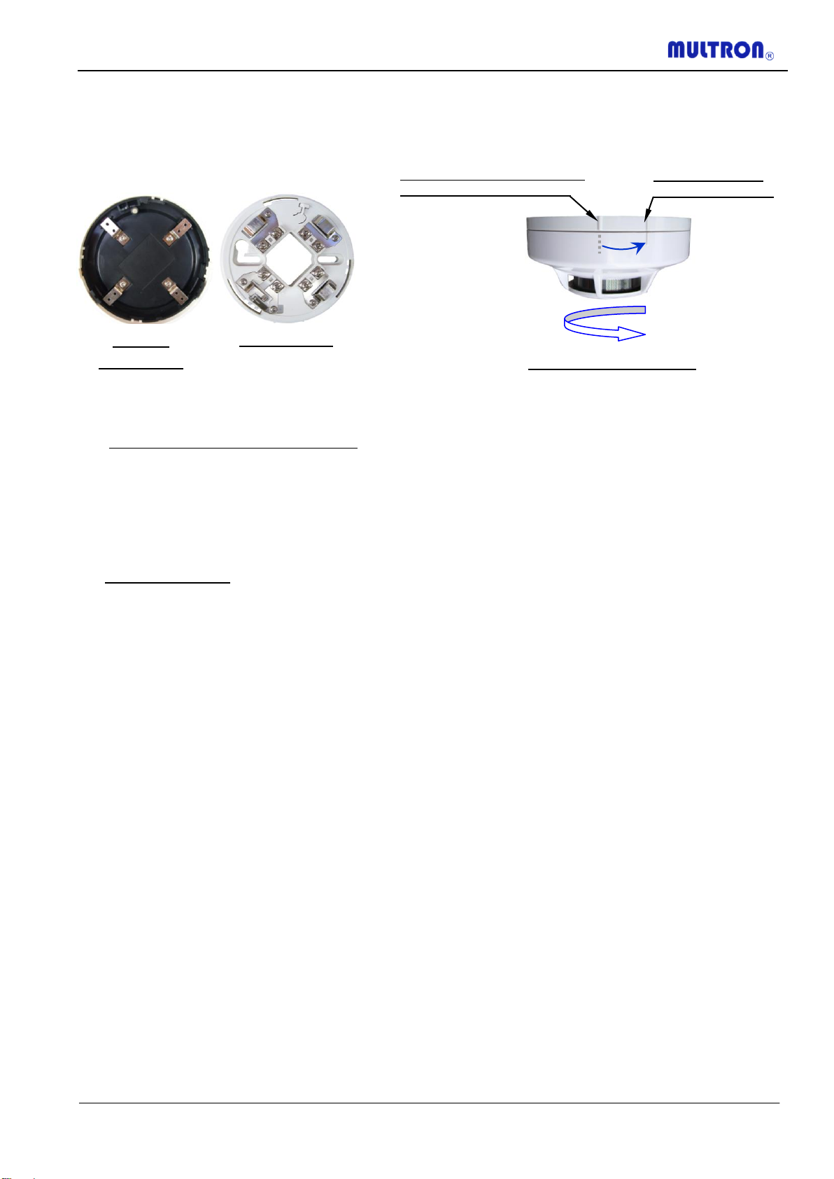
5.3) After proper termination on all the detector bases is done, cap the Detector Head onto the Base using the
line marking at the side as a guideline to assist in positioning. Twist the Detector Head clockwise to secure
it onto the Base, and the second line marking of both the Detector Head and Base shall be aligned when
properly installed.
6) Troubleshooting
No Alarm when the Detectors are tested :-
6.1) Ensure that the Fire Alarm Panel is power up without any fault indications.
6.2) Check whether the Detector is securely installed onto the Base.
6.3) There should be 24VDC between terminals 1 and 5 at the Base. Otherwise, check the Zone output at the
Fire Alarm Panel and the wiring for open circuit.
Fault or False Alarm:
6.4) Check the LED on the detector whether it is in Alarm (Red), otherwise it may be due to a Panel problem.
6.5) Check the wiring for open or short circuit, and rectify if necessary.
6.6) Check whether the correct value of End-of –Line resistor is been used.
6.7) Check whether the Smoke Chamber is dusty, and needs to be cleaned or replaced.
6.8) May be caused by ambient conditions due to wrong detector positioning, such as to close to cooking
appliances, exhaust fume, or exposed to high air velocities from ventilation systems, and etc…
7) Caution
7.1) The Detectors installation and maintenance must be performed by qualified technical personnel.
7.2) Ensure that there is no obstruction within a perimeter of 0.5m around the detector.
7.3) The distance from the detector any Air Diffuser Outlet shall not be less than 1.5m.
7.4) The distance from the detector to any wall shall not be less than 0.5m.
7.5) The detector shall be installed horizontally. If it has to be installed slanted, the gradient angle should not
be more than 45o.
7.6) The Detector Alarm Status LED Indicator shall be easily visible, otherwise a Remote Status LED Indicator
shall be provided at a prominent location.
7.7) Ensure that Dust Covers, if any, are removed once the Fire Alarm System is commissioned.
7.8) Test and maintained the Fire Alarm System regularly to ensure that it is in proper operation condition.
7.9) Besides the above, installation of the detectors must be in compliance to the rules and regulation of the
Authority having jurisdiction, and the relevant Code-of-Practice.
Detector
Bottom View
Detector Base
Line aligned once
Detector is secured
Side View of the Detector
Use mark as guide to position
the Detector onto the Base
Position and twist the
Detector Head clockwise
to secure onto the Base
Table of contents
Popular Smoke Alarm manuals by other brands

diagral
diagral DD355 manual

First Alert
First Alert PC1210 user manual

Matelec
Matelec FSA-60000 quick start guide

Heatit Controls
Heatit Controls HEATIT Z-SMOKE MULTISENSOR quick guide

Honeywell
Honeywell Fire Sentry SS4-AUV Installation guide and operating manual

Emerald Planet
Emerald Planet EP-SA-Li10 user manual