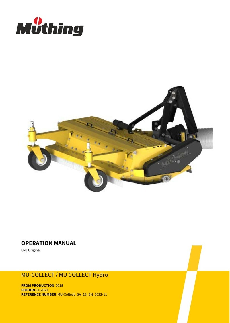
Muthing MZO 2011 User manual

OPERATION MANUAL
MZO2011
FROM PRODUCTION 2012
EDITION 03.2018
REFERENCE NUMBER MZO_BA_12_2018-03_EN
EN| Original

Machine identification
In order for your dealer to assist you as efficiently as possible, you will need to provide some information
about your machine.
Please enter the information here.
Designation
Working width
Weight
Machine number
Additional equipment
Dealer'saddress
Manufacturer'saddress
The copyright and usage rights are owned by Müthing GmbH & Co KG, Soest. Reproduction, transfer to other media, translation or the use of
extracts or parts of this manual without the explicit permission of Müthing GmbH & Co KG, is not permitted. All rights reserved. The contents of
this operating manual are subject to change without notice. The right to technical revision is reserved
MüthingGmbH &Co. KGSoest
AmSilberg 23
59494 Soest
Germany

3
Handoverdeclaration
Handover declaration
– Fill out this sheet with your dealer.
– Then separate this sheet from the operating manual and send it to the manufacturer within 10 days of delivery.
Only in this way will the guarantee be effective from the date of delivery
.
I have bought the machine described below from Müthing GmbH & Co. KG, Soest, and confirm
full delivery and handover of the machine including the operating manual and replacement parts
list, as well as training in operating the devices with safety and warning instructions from your
sales partner.
I confirm additionally that I have read and understood the operating manual and am in agreement
with the information contained therein. This applies in particular to the chapter Safety.
Client
Machine
Name First name
Address
Post code Town/city
Telephone Fax
E-mail Date
Machine MU- Serial number
Working width Gear box
Rigid mounting Non-rigid
mounting
Year of construction Delivery date
Delivered by
Signatureof client Signatureandstamp ofsalespartner
To
Müthing GmbH & Co. KG
Am Silberg 23
59494 Soest
Germany

4
Handoverdeclaration

5
Handoverdeclaration–Copy
Handover declaration – Copy
– This sheet remains with the client in the operating manual
I have bought the machine described below from Müthing GmbH & Co. KG, Soest, and confirm
full delivery and handover of the machine including the operating manual and replacement parts
list, as well as training in operating the devices with safety and warning instructions from your
sales partner.
I confirm additionally that I have read and understood the operating manual and am in agreement
with the information contained therein. This applies in particular to the chapter Safety.
Client
Machine
Name First name
Address
Post code Town/city
Telephone Fax
E-mail Date
Machine MU- Serial number
Working width Gear box
Rigid mounting Non-rigid
mounting
Year of construction Delivery date
Delivered by
Signatureof client Signatureandstamp ofsalespartner

6
Handoverdeclaration–Copy

7
TableofContents
Table of Contents
Handover declaration ................................ 3
Handover declaration – Copy ................... 5
About this operating manual .................... 8
Target group 8
Safety 8
Training 8
Other applicable documents 8
Symbols 9
Safety .......................................................... 10
For your safety 10
Warning signs 10
Definitions 13
Who is allowed to operate the machine? 13
Fitting 13
Putting the machine into operation 13
Care and maintenance 15
Further regulations 16
Familiarising yourself with the machine . 17
Range of application of the machine 17
Features of the machine 18
Designation of components 19
Technical specifications 20
Delivery and assembly .............................. 21
Checking the scope of delivery 21
Coupling the machine ............................... 22
Requirements 22
Chopper 22
PTO shaft 23
Hydraulics 24
Preparation ................................................. 25
Working depth 25
Press wheel 26
Shear bars 26
Guide plates 27
Driving on the road .................................... 28
Transport without coupling 28
Chopping .................................................... 29
Tips 29
Work position 29
Task 30
Cleaning and care ...................................... 33
Cleaning 33
Care 33
Parking and storage .................................. 34
Setting down the machine in a
secure position 34
Storing the machine 36
Maintenance ............................................... 37
For your safety 37
General information 38
Maintenance intervals and setting work 41
Lubricating work 42
PTO shaft 44
Gearbox oil 46
Chopping blades 47
V-belt 48
Fault elimination ........................................ 49
Disposal of the machine ........................... 51
EC Declaration of Incorporation .............. 52
In accordance with the EC Directive
2006/42/EG 52
Index ........................................................... 53

MU-L
8
Aboutthisoperatingmanual
About this o perating manua l
Target group
This operating manual is intended for trained machine operators and
persons who are otherwise qualified to carry out landscape work and
who have received training in how to use this machine.
Safety
Familiarise yourself with the contents of this operating manual which
are relevant for your activity before commissioning or assembling the
machine. Always read through the safety instructions in the chapter
“Safety” and observe the warning information in the individual chapters.
In this way, you will achieve optimum work results and operational safe-
ty.
For the employer:
Staff must be instructed in the safe handling of the machine before the
initial commissioning. Untrained or unauthorised persons are not per-
mitted to use the machine.
The following are included in this training:
•Checking that staff possess the necessary requirements for safely
handling the machine.
•Handing out the operating manual and the other relevant and appli-
cable documents or an intensive course of training which, in
particular, includes the safe handling of the machine.
Regular instruction ses-
sions
Instruct your staff regularly, but at least once a year, concerning the ba-
sic procedural measures for safely handling the machine.
Training
You will receive training from your dealership concerning using the con-
trols, safe operation and care of the machine. Commissioning without
first receiving training is not permitted.
Other applicable
documents
In addition to the operating manual, other documents also form an inte-
gral part of the machine:
EC Declaration of Incorporation Integral part of this operat-
ing manual
Chapter »EC Declara-
tion of Incorporation«,
page 52
List of approved balers Integral part of the delivery
with this machine
Certification by the authorised specialist
workshop that the machine has been
correctly fitted
Integral part of the delivery
with this machine
Spare parts list Integral part of the delivery
with this machine
PTO shaft operating manual Integral part of the delivery
with this machine

MU-L
9
Aboutthisoperatingmanual
Symbols
In order to make this manual clear and easy to read, we have used var-
ious symbols. They are explained below:
•A bullet point accompanies each item in a list
A triangle indicates operating functions which must be performed
An arrow indicates a cross-reference to other sections of this manual
[+] A plus sign indicates an accessory that is not included in the stand-
ard version.
Pictograms
We have also used pictograms to help you find instructions more quick-
ly:
This symbol indicates information, tips and instructions about operation.
This symbol indicates tips for assembly or adjustment work.
This symbol indicates examples that help you to understand the instruc-
tions better.
Parts in the text which refer to individual machines or to conditions have
a coloured background. After the coloured section, the text then applies
again to all machines. For example:
Only for machines with a pneumatic brake system
Connect hydraulic hoses
The warning triangle indicates warning information. Failure to ob-
serve these safety instructions can result in:
•Moderate to serious injury
•Fatal injury
You will find the warning information associated with individual op-
erations, where it is important to observe the warning information
before these operations are carried out.
You will also find safety instructions in the chapter »Safety« which
cannot be assigned to any particular operations, but increase your
ability to work safely in different situations.
This sign indicates important instructions regarding the machine.
Failure to observe these safety instructions can result in:
•Serious faults in the correct operation of the machine.
•Damage to the machine.
Connect brake hoses

MU-L
10
Safety
Safety
For your safety
This chapter contains general safety instructions. Each chapter of the
operating manual contains additional warning instructions which are not
described here. Observe the safety instructions:
•in the interest of your own safety,
•in the interest of the safety of others
•to ensure the safety of the machine
Numerous risks can result from handling landscaping machines the
wrong way. Therefore, always work with particular care and never under
time pressure.
For the employer:
Inform personnel working with the machine of these safety instructions
at regular intervals and according to statutory regulations.
Warning signs
On the machine you will find labels that serve to ensure your safety. The
labels must not be removed. If labels become illegible or begin to peel
off, new labels can be ordered and attached in the appropriate places.
STOP
Min. 250 mm
AC 351057
AC 351057
AC 351057
AC 351057

MU-L
11
Safety
Meaning of warning
signs
Read the operating manual carefully and follow the instructions
Commissioning of the machine must not take place before the operating
manual has been read and understood. This particularly applies to safe-
ty instructions.
Riding on the machine is prohibited
It can result in serious or even fatal injury.
Do not remove protective devices
Never open or remove the protective devices while the tractor's engine
is running. Never operate the machine without the protective device.
Be aware of the danger of being pulled in
There is a danger of being pulled into the PTO shaft in the event of in-
appropriate use.
Shackles
Only raise the machine using loading equipment at the points indicated.
Rotating and trailing machine parts
Only approach the machine when all machine parts have stopped mov-
ing.
AC 351057
STOP

MU-L
12
Safety
Danger of objects being thrown out
During operation, there is a danger of objects such as stones being
picked up and thrown out by the machine. Ensure that no persons are
present in the hazard area.
Retighten screws
After the first hours of operation, and as required, all screws must be
checked and tightened if necessary. Vibrations might have loosened the
screwed connections.
Minimum clearance from the ground: 250 mm
The minimum clearance from the ground must not fall below 250 mm
during work. If the blades come into contact with stones, this may create
sparks, which could cause a fire.
Min. 250 mm

MU-L
13
Safety
Definitions
All direction information is given in relation to the direction of travel of
the machine:
Who is allowed to
operate the ma-
chine?
Only qualified personnel
Only qualified persons who have been informed of the dangers associ-
ated with handling the machine are permitted to operate, service or re-
pair the machine. As a rule, such persons are trained and experienced
in agricultural work or have been thoroughly trained in a similar fashion.
Fitting
Authorised specialist workshop
Only an authorised specialist workshop must fit the machine to an ap-
proved baler. The specialist workshop will issue a certificate to confirm
that the machine has been fitted correctly. The machine must not be
started up if an installation certificate has not been issued.
Failure to observe these instructions can result in serious or fatal injury.
Putting the ma-
chine into opera-
tion
Training required before commissioning
The machine must not be put into operation until the user has been giv-
en proper training by an employee of the dealer, a factory representa-
tive, or an employee of the manufacturer. Commissioning without train-
ing can lead to damage to the machine due to false operation or acci-
dents can happen.
Ensure that the machine is in perfect working condition
Do not operate the machine unless it is in perfect working condition.
Check all important components and replace any defective components
before starting the machine. Defective components can cause damage
to equipment and personal injury.
Up
Right
Down
Left
Front
Rear

MU-L
14
Safety
Do not remove the protective equipment
The protective equipment must not be removed or by-passed. Check all
protective equipment before starting the machine. Unprotected ma-
chine parts can cause serious or fatal injury.
Riding on the machine is strictly prohibited
People or objects must never be transported on the machine. Riding on
the machine poses a risk to life and limb and is strictly prohibited.
Height of the machine and overhead power lines
If a height of 4.00 m is exceeded when folding the machine in and out,
the machine must not be folded in the vicinity of live overhead power
lines. Danger of electrocution! Should the machine come into contact
with a live overhead power line:
•Do not attempt to exit the tractor cabin
•Do not touch any metal parts on the tractor
•Do not create any conductive contact with the ground
•Warn all persons in the area not to approach the tractor or the
machine
•Wait for help from professional emergency service personnel as
power in the live overhead power line must first be switched off
Never climb onto the machine beneath live overhead power lines. The
voltage can jump across even if the lines are not actually touching the
machine.
Check the hazard area
Before driving off, folding out, and operating the machine and during op-
eration, check its hazard area. Make sure that you have an adequate
view. Do not begin work until the hazard area is cleared of any persons
or objects. Information regarding the hazard area can be found in the
corresponding chapter.
Chapter »Chopping«, section »Task«, Page 30.
Parts could be ejected from the machine at high speed in certain cir-
cumstances. The hazard area, particularly in front of and behind the ma-
chine, must be cleared of any persons, animals or objects before start-
ing.
Any use of the machine without verification of the hazard area can lead
to serious or fatal accidents.
Retighten all nuts, bolts and screws
Nuts, bolts and screws should be checked at regular intervals and tight-
ened if necessary. Screws can come loose unnoticed while operating.
Damage to the machine or accidents may be caused as a result.
What to do in the event of a fault
In the event of a malfunction, shut down and secure the machine imme-
diately. The fault may be eliminated immediately, or a specialist work-
shop must be assigned the task. Further operation of the machine can
lead to damage to the machine or injury to persons.

MU-L
15
Safety
Care and mainte-
nance
Observe the care and maintenance intervals
Observe prescribed intervals for maintenance checks and inspections
specified in the operating manual. If these periods are not observed, this
can lead to damage to the machine, poor quality of work or accidents.
Use original replacement parts
Many components have special properties that are essential for the sta-
bility and correct operation of the machine. Unsuitable spare parts or ac-
cessory parts or incorrectly performed repairs or changes can cause
damage to the machine, accidents or serious injury.
Müthing strongly recommends using only approved original Müthing ac-
cessories and spare parts. Müthing can guarantee the safety, reliability
and suitability of these parts only.
Use of non-original Müthing spare parts shall invalidate any warranty
claims.
When performing any care and maintenance work:
•Switch off the PTO stub shaft
•Depressurise the hydraulic system
•Park the tractor safely, switch off the engine
•Secure the tractor against being started up by third parties
•Make sure the machine is standing securely. Provide additional sup-
port as required
•Do not use parts of the machine as climbing aids; use only secure
steps, ladders or other means of access
•Secure the machine against rolling away
•Never reach into the V-belt while it is moving
It is only possible to guarantee work safety during care or maintenance
work through observing these regulations.
Turn off the electrical supply
Prior to carrying out work on the electrical system, disconnect the sys-
tem from the power supply. Systems supplied with electrical power can
cause damage to equipment and personal injury.

MU-L
16
Safety
Replace hydraulic hoses
Replace hydraulic hoses every six years. Hydraulic hoses can age with-
out any externally visible damage. Defect hydraulic lines can lead to se-
vere or fatal injuries.
Caution when cleaning with a high-pressure cleaner
The machine can be cleaned using either water or a steam jet. Only use
a low pressure to clean bearings, fans, signal mixer units, plastic parts
and hydraulic hoses. Excessively high pressures can cause damage to
these parts.
Before carrying out welding work, disconnect the battery and al-
ternator
Before carrying out any electric welding work on the attached machine,
disconnect the tractor battery and the alternator. This avoids damage to
the electrical system.
Tighten all screwed connections
All screw connections that are released during maintenance and repair
work must now be retightened. Loose screwed connections can cause
bolts to undo without you noticing during your work. As a result, ma-
chine parts can become detached. Otherwise, this may result in severe
injury or damage to equipment.
Further regula-
tions
Observe the regulations
In addition to these safety instructions, observe the following:
•Accident prevention regulations
•Generally recognised safety regulations, occupational health re-
quirements and road traffic regulations
•Information and instructions in this operating manual
•Operation, maintenance and repair instructions

MU-L
17
Familiarisingyourselfwiththemachine
Familiarising yourself with the machine This chapter contains general information on your machine as well as
information on:
•Range of application
•Features
•Designation of components
•Technical specifications
Range of applica-
tion of the ma-
chine
The machine may only be used for its intended agricultural or associat-
ed purpose in conjunction with an approved baler.
Since the conditions of use are very varied, the user must pay particular
attention to the machine's performance limits. The machine must be
switched off immediately if there is any indication of overstress.
Proper use
The machine should only be used for the designated work as described
in this operating manual. Any application other than or beyond this is
considered improper use.
Examples of improper use:
•Transporting persons or objects
•Cutting of any products other than those specified or those of a sim-
ilar nature
»Range of application of the machine«
•Transferring power to other objects
•Fitting to balers that have not been approved. A list of the approved
balers is provided with the machine and is an integral part of the de-
livery of the machine
•Working widths under 250
•Any type of ground work
•Use of the machine in a position in which the tools do not point to-
wards the ground, for example in a vertical position
The manufacturer and dealers are not liable for damage caused by im-
proper use. The risk is borne solely by the user.
Tool Purpose
M chopping blade Chopping straw, hay, grass that has
started to dry out or other vegetation of
a similar consistency, which has been
deposited in swaths.

MU-L
18
Familiarisingyourselfwiththemachine
Features of the
machine
Robust housing in optimised form
The housing is particularly robust for heavy use and is designed in an
optimised form.
Power transmission
Power is transmitted to a gear box via a PTO shaft. From there, the V-
belt is driven by another PTO shaft.
Safety
The machine is constructed in accordance with EU regulations, for max-
imum possible safety of operation.

MU-L
19
Familiarisingyourselfwiththemachine
Designation of
components
Switches the
gear box on or
off
Adjusts the
lower shear bar
Press
wheel
Front stone impact
protection
Runner
Attachment
carrier
Housing
Gear box PTO shaft protec-
tive cover
Protective cover
for V-belt
Adjusts the up-
per shear bar
Chopping blades
Adjusts the
press wheel
Hydraulic cylinder
Limiter chain

MU-L
20
Familiarisingyourselfwiththemachine
Technical specifi-
cations
MZO 2011
Height (m)
Uncoupled 1.20
Width (m)
Machine width 2.50
Working width 2.00
Depth (m)
In transport position 1,56
Total weight (kg)
Depending on equipment level, approx. 850
Rotational speed of rotor (rpm)
PTO stub shaft 1000 rpm 3000
Power requirement (kW)
Minimum 80
Maximum permitted 150
Working depth (mm)
Minimum above ground 250
Maximum above ground 500
PTO shaft
Model GE 2400 MZO
Number of tools
Chopping blades, depending on the rotor 44 / 88
Lubricants
Gear-box oil, fully synthetic SAE 75/90
Noise level (dbA)
In the workplace < 80
Paint colours
Yellow RAL 1007
Black RAL 9005
Height
Width
Depth
Table of contents
Other Muthing Lawn And Garden Equipment manuals
Popular Lawn And Garden Equipment manuals by other brands

Acqua
Acqua SPRINT 1.5 Maintenance schedule

Makita
Makita UM104D instruction manual

Outdoor Essentials
Outdoor Essentials WOODLANDS 12x12 PERGOLA KIT installation instructions

Shindaiwa
Shindaiwa T282 Owner's/operator's manual

POND KING
POND KING Turtle Trap Assembly instructions

growland
growland AQUAvalve AutoPot 8 POT system manual