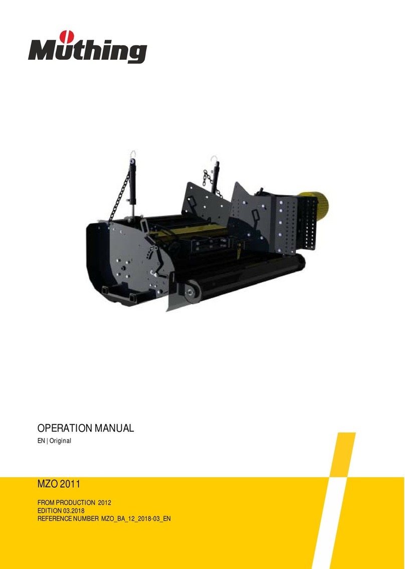
Muthing MU-COLLECT User manual

OPERATION MANUAL
MU-COLLECT / MU COLLECT Hydro
FROM PRODUCTION 2018
EDITION 11.2022
REFERENCE NUMBER MU-Collect_BA_18_EN_2022-11
EN | Original

Machine identification
In order for your dealer to assist you as efficiently as possible, you will need to provide some information
about your machine. Please enter the information here.
Designation
Working width
Weight
Machine number
Additional equipment
Dealer's address
Manufacturer's address
The copyright and usage rights are owned by Müthing GmbH & Co. KG Soest. Reproduction, transfer to other media, translation or the use of
extracts or parts of this manual without the explicit permission of Müthing GmbH & Co. KG Soest , is not permitted. All rights reserved. The contents
of this operating manual are subject to change without notice. Technical changes reserved.
Müthing GmbH & Co. KG Soest
Am Silberg 23
59494 Soest
Germany

3
Handover declaration
– Fill out this sheet with your dealer.
– Then separate this sheet from the operating manual and send it to the manufacturerwithin 10 days of delivery. Only
in this way will the guarantee be effective from the date of delivery
.
I have bought the machine described below from Müthing GmbH & Co. KG Soest, and confirm full
delivery and handover of the machine including the operating manual and spare parts list, as well
as training in operating the devices with safety instructions and warning information from your
dealer.
I confirm additionally that I have read and understood the operating manual and am in agreement with the
information contained therein. This applies in particular to the chapter Safety.
Client
Machine
--------------------------------------------------------- -------------------------------------------------------------------------
Signature of client Signature and stamp of sales partner
Name First name
Address
Post code Town/city
Telephone Fax
E-mail Date
Machine MU- Serial number
Working width Gear-box
Rigid mount-
ing Non-rigid
mounting
Year of con-
struction Delivery date
Delivered by
To
Müthing Gmbh & Co. KG Soest
Am Silberg 23
59494 Soest
Germany

4
Handover declaration

5
Handover declaration – Copy
– This sheet remains with the client in the operating manual
I have bought the machine described below from Müthing GmbH & Co. KG Soest, and confirm full
delivery and handover of the machine including the operating manual and spare parts list, as well
as training in operating the devices with safety instructions and warning information from your
dealer.
I confirm additionally that I have read and understood the operating manual and am in agreement with the
information contained therein. This applies in particular to the chapter Safety.
Client
Machine
--------------------------------------------------------- -------------------------------------------------------------------------
Signature of client Signature and stamp of sales partner
Name First name
Address
Post code Town/city
Telephone Fax
E-mail Date
Machine MU- Serial number
Working width Gear-box
Rigid mount-
ing Non-rigid
mounting
Year of con-
struction Delivery date
Delivered by

6
Handover declaration – Copy

7
Table of contents
Table ofcontents
Handover declaration ................................ 3
Handover declaration – Copy ................... 5
About this operating manual .................... 8
Target group 8
Safety 8
Instruction 8
Other applicable documents 8
Symbols 9
Safety .......................................................... 10
For your safety 10
Warning signs 10
Definitions 13
Who is allowed to operate the machine? 13
Coupling 14
Centre of gravity 15
Road transport 17
Putting the machine into operation 17
Uncoupling the machine 19
Care and maintenance 19
Further regulations 20
Familiarising yourself with the machine . 21
Range of application of the machine 21
Features of the machine 22
Designation of components 23
Technical specifications 26
Delivery and assembly .............................. 30
Checking the scope of delivery 30
Fitting 30
MU-Collect adapter .................................... 31
Rigid implement triangles 31
Attachment kits 32
Coupling the machine ............................... 33
Coupling triangle 33
Two-point connection 34
Suction hose 35
Mechanical drive 36
Hydraulic drive 38
Preparation ................................................. 39
Blower unit 39
Cutting bar [+] 43
Mulching working depth 44
Scarifying working depth 45
Transport device [+] 46
Driving on the road .................................... 47
Transport position 47
Transport without coupling 47
Mulching ..................................................... 48
Task 48
After mulching 50
Scarifying ................................................... 51
Task 51
Cleaning and care ..................................... 52
Cleaning 52
Care 52
Parking and storage .................................. 53
Setting down the machine in a
secure position 53
Storing the machine 54
Maintenance ............................................... 55
For your safety 55
General information 56
Maintenance intervals and setting work 59
Lubricating work 60
PTO shaft 62
Transmission oil 63
Tools 64
Scarifying blade 66
V-belt 68
Runners 71
Accessory .................................................. 72
Wear insert 72
Cutting bar 72
Short chopping bar 72
Scarifying blade 72
Support wheels 73
Operating hours counter 73
Fault elimination ........................................ 74
Screw conveyor 76
Disposal of the machine ........................... 77
EU-conformity declaration ........................ 78
EC Directive
2006/42/EG 78
EC Directive
2006/42/EG 79
UK Declaration of Conformity .................. 80
UKCA 80
UKCA 81
Index ........................................................... 82

MU-Collect / MU-Collect Hydro
8
About this operating manual
Target group
This operating manual is intended for trained machine operators and
persons who are otherwise qualified to carry out landscape work and
who have received training in how to use this machine.
Safety
Familiariseyourself with the contents of this operating manualwhich are
relevant for your activity before commissioning or assembling the ma-
chine. Always read through the safety instructions in the chapter “Safe-
ty” and observe the warning information in the individual chapters. In
this way, you will achieve optimum work results and operational safety.
For the employer
Staff must be instructed in the safe handling of the machine before the
initial commissioning. Untrained or unauthorised persons are not per-
mitted to use the machine.
The following are included in this training:
•Checking that staff possess the necessary requirements for safely
handling the machine.
•Handing out the operating manual and the other relevant and appli-
cable documents or an intensive course of training which, in particu-
lar, includes the safe handling of the machine.
Regular instruction ses-
sions
Instruct your staff regularly, but at least once a year, concerning the ba-
sic procedural measures for safely handling the machine.
Instruction
You will receive training from your dealership concerning using the con-
trols, safe operation and care of the machine. Commissioning without
first receiving training is not permitted.
Other applicable
documents
In addition to the operating manual, other documents also form an inte-
gral part of the machine:
EU-conformity declaration Integral part of this operat-
ing manual
Chapter »EU-conform-
ity declaration«, Page 78
Spare parts list Integral part of the delivery
with this machine
PTO shaft operating manual Integral part of the delivery
with this machine
In case of a later conversion from mulch-
ing to operation with scarifying blades Certificate of the certified
professional workshop
about the conversion
In the event of a later conversion from
scarifying to operation with mulching
tools
Certificate of the certified
professional workshop
about the conversion

MU-Collect / MU-Collect Hydro
9
About this operating manual
Symbols
In order to make this manual clear and easy to read, we have used var-
ious symbols. They are explained below:
•A bullet point accompanies each item in a list
A triangle indicates operating functions which must be performed
An arrow indicates a cross-reference to other sections of this manual
[+] A plus sign indicates an accessory that is not included in the stand-
ard version.
Pictograms
We have also used pictograms to help you find instructions more quick-
ly:
This symbol indicates information, tipsand instructions about operation.
This symbol indicates tips for assembly or adjustment work.
This symbol indicates examples that help you to understand the instruc-
tions better.
Parts in the text which refer to individual machines or to conditions have
a colored background. After the colored section, the text then applies
again to all machines. For example:
Only for MU-Farmer/S with pneumatic brake system
Connect hydraulic hoses
The warning triangle indicates warning information. Failure to ob-
serve these safety instructions can result in:
•Moderate to serious injury
•Fatal injury
You will find the warning information associated with individual oper-
ations, where it is important to observe the warning information be-
fore these operations are carried out.
You will also find safety instructions in the chapter »Safety« which
cannot be assigned to any particular operations, but increase your
ability to work safely in different situations.
This sign indicates important instructions regarding the machine.
Failure to observe these safety instructions can result in:
•Serious faults in the correct operation of the machine.
•Damage to the machine
Connect brake hoses

MU-Collect / MU-Collect Hydro
10
Safety
Safety
For your safety
This chapter contains general safety instructions. Each chapter of the
operating manual contains additional warning instructions which are not
described here. Observe the safety instructions:
•In the interest of your own safety,
•In the interest of the safety of others
•To ensure the safety of the machine
Numerous risks can result from handling landscaping machines the
wrong way. Therefore, always work with particular care and never under
time pressure. Therefore, always work with particular care and never
under time pressure.
For the employer
Inform personnel working with the machine of these safety instructions
at regular intervals and according to statutory regulations.
Warning signs
On the machine you will find labels that serve to ensure your safety. The
labels must not be removed. If labels become illegible or begin to peel
off, new labels can be ordered and attached in the appropriate places.
STOP
AC 351057
AC 351057
On machines with
hydraulic drive

MU-Collect / MU-Collect Hydro
11
Safety
Meaning of warning
signs
Read the operating manual carefully and follow the instructions
Commissioning of the machine must not take place beforethe operating
manual has been read and understood. This particularly applies to safe-
ty instructions.
Do not stand between the carrier vehicle and the machine
Standing between the carrier vehicle and the machine while the engine
is running is prohibited, especially during coupling and uncoupling. The
carrier vehicle must also be secured so that it cannot roll away.
Riding on the machine is prohibited
It can result in serious or even fatal injury.
Do not remove protective devices
Do not open or remove the protective devices while the engine of the
carrier vehicle is running. Never operate the machine without the pro-
tective device.
Be aware of the danger of being pulled in
There is a danger of being pulled into the PTO shaft in the event of in-
appropriate use.
Shackles
Only raise the machine using loading equipment at the points indicated.
Proceed with great care in the event of leaking hydraulic fluid
Do not look for leakage points without correct protection. Fine oil jets
could penetrate eyes and skin under high pressure. Observe the corre-
sponding safety instructions in the operating manual.
AC 351057

MU-Collect / MU-Collect Hydro
12
Safety
Rotating and trailing machine parts
Only approach the machine when all machine parts have stopped mov-
ing.
Danger of objects being thrown out
During operation, there is a danger of objects such as stones being
picked up and thrown out by the machine. Ensure that no persons are
present in the hazard area.
Danger from moving machine parts
Nobody is permitted to remain within the hazard area during operation.
Do not stand in the slewing range
There is an extreme risk of injury within the slewing range from slewing
or folding machine parts.
Check the rotational speed of the PTO stub shaft
Connect PTO shaft to a PTO stub shaft with an appropriate rpm.Always
switch off the PTO stub shaft when working on the machine.
Retighten screws
After the first hours of operation, and as required, all screws must be
checked and tightened if necessary. Vibrations might have loosened the
screwed connections.
STOP
Example

MU-Collect / MU-Collect Hydro
13
Safety
Definitions
All direction information is given in relation to the direction of travel of
the machine:
Who is allowed to
operate the ma-
chine?
Only qualified personnel
Only qualified persons who have been informed of the dangers associ-
ated with handling the machine are permitted to operate, service or re-
pair the machine. As a rule, such persons are trained machine opera-
tors or have had similar intensive training.
Up
Right
Down
Left
Front
Rear

MU-Collect / MU-Collect Hydro
14
Safety
Coupling
Increased risk of injury
There is an increased risk of injury when the machine is being coupled
to the carrier vehicle. Therefore:
•The carrier vehicle must be fitted with the corresponding adaptor in
order to be coupled to the machine.
•Only couple the machine with the road chassis raised
•Secure the carrier vehicle so that it cannot roll away.
•Never stand between the carrier vehicle and the machine during
coupling.
•Actuate the power lever slowly and carefully.
Failure to observe these instructions can result in serious or fatal injury.
Connect electric wires or cables only after mounting the attach-
ment
The electrical supply to the carrier vehicle must not be connected up
during the fitting of the lighting equipment. Short circuits and damage to
the electronics are possible.
Only connect hydraulics at zero pressure
Only connect the hydraulic hoses to the carrier vehicle while the hydrau-
lic system on the carrier vehicle and machine is de-pressurised. A hy-
draulic system under pressure can trigger unpredictable machine
movements.
High pressures in the hydraulic system
The hydraulic system is under high pressure. Regularly check all lines,
tubes and screwed connections for leaks and externally visible damage.
Only use suitable tools when looking for leaks. Rectify any damage im-
mediately. Oil escaping under pressure may result in injuries and fires.
In the event of injuries, seek medical attention immediately.
Color-coded hydraulic hoses
To avoid operating errors, the sockets and plugs of the hydraulic con-
nections between the carrier vehicle and the machine should be color-
coded. Wrongly connected hydraulic hoses can trigger unpredictable
movements of the machine.

MU-Collect / MU-Collect Hydro
15
Safety
Centre of gravity
Observe the total weight, axle loads, tyre load-bearing capacity
and minimum ballast specifications
The front or rear mounting of machines must not cause the carrier vehi-
cle's permissible total weight, permissible axle loads, or tyre load-bear-
ing capacity to be exceeded. The front axle must bear at least 20 % of
the empty weight of the carrier vehicle to ensure steering capability.
You can calculate:
•Total weight
•Axle loads
•Minimum added weight
Data
For this calculation, some data is required out of the following docu-
ments and measurement results:
•Operating manual of carrier vehicle
•This operating manual
•Measurement results from carrier vehicle and attached machine
Data from the operating manual of the carrier vehicle:
Data from this operating manual:
Data which you can determine by measuring:
•(A) unladen weight
•(B) front axle load
•(C) rear axle load
•(H) wheel base of carrier vehicle
Please take into consideration, for example, the weight of water in the
tyres, accessories, etc.
•(D) Total weight of the machine when rear-mounted; the supporting
load with the machines attached
•(E) Total weight of the machine when front-mounted
•(G) Distance between the lower link ball midpoint and the machine's
centre of gravity when rear-mounted. With machines attached, G=0.
•(F) Distance between the machine's centre of gravity when front-
mounted and the front-axle midpoint
•(I) distance between the rear axle midpoint and the lower link ball
midpoint. For rear-mounted machines between rear axle midpoint to
drawbar coupling midpoint or hitch ball
ED
A
BC
FHIG

MU-Collect / MU-Collect Hydro
16
Safety
Calculation
The measured values can now be inserted into the formulas.
Ballast with front
weights
Calculating the ballast with front weights
on rear-mounted machines.
Front ballast in kg =
Ballast with rear weights
Calculating the ballast with rear weights
on front-mounted machines.
Rear ballast in kg =
Front axle load
Calculating the actual front axle load
Front axle load in kg =
Total weight
Calculating the actual total weight
Total weight =
Rear axle load
Calculating the actual rear axle load
Rear axle load in kg = actual total weight - actual front axle load
Tyre load-bearing capac-
ity
Data on the tyre load-bearing capacity of the front and rear tyres can be
found in the tyre manufacturer's documentation.
•The front tyre load-bearing capacity for two wheels is equal to twice
the permissible tyre load-bearing capacity of a single front wheel.
•The rear tyre load-bearing capacity for two wheels is equal to twice
the permissible tyre load-bearing capacity of a single rear wheel.
Summary
Check if the following conditions are met:
•The actual rear axle load is less than the permissible values for the
axle load stated in the operating manual of the carrierer vehicle
•The actual total weight is less than the permissible values for the to-
tal weight stated in the operating manual of the carrierer vehicle
•The sum of the permissible rear wheel load capacity is higher than
the real rear wheel load capacity
•The sum of the permissible front wheel load capacity is higher than
the real front wheel load capacity
If all conditions are met, the machine may be attached to this carrier ve-
hicle.
You can use a sufficiently large weigh-bridge to determine the total
weight, the rear axle load and the front axle load by weighing.
DIG+ BH02 A H,+–FH+
-------------------------------------------------------------------------------------------
EFCH045 A H,+–HIG++
-------------------------------------------------------------------------------------
EFHBHDIG+–++ H
---------------------------------------------------------------------------------------
EAD++

MU-Collect / MU-Collect Hydro
17
Safety
Road transport
Make sure that the condition of the machine conforms to traffic
regulations
The machine must conform to current traffic regulations if you intend to
drive it on public roads. This includes for example:
•Fitting lighting equipment, warning devices and protective devices
•Observing the permissible transport widths, transport weights, axle
loads, tyre load-bearing capacity and total weights
The driver and owner of the vehicle are liable if traffic regulations are not
observed.
Closing ball valves
If ball valves are provided on the hydraulic lines or the chassis cylinders,
the ball valves must be closed for road transport. The accidental actua-
tion of control devices on the carrier vehicle could otherwise cause
movements on the machine.Accidents or damage to the machine may
be caused as a result.
Check release cable for the quick-release coupling
Release cables must hang loose and must not, when in their lowered
position, release the couplings of their own accord. Otherwise, attached
machines can detach themselves from the three-point hitch.
Riding on the machine is strictly prohibited
People or objects must never be transported on the machine. Riding on
the machine poses a risk to life and limb and is strictly prohibited.
Take altered driving and braking behaviour into account
Driving and braking performance is altered when the machine is at-
tached to the tractor. Take the width and balancing weight of the ma-
chine into consideration, especially when cornering. A driving style
which not adjusted to the road conditions can lead to accidents.
Drive at a suitable speed
Always adjust your driving speed to the road conditions. Driving at ex-
cessive speeds in poor road conditions can create extremely high forc-
es which can severely load or overload the carrier vehicle and machine.
Driving at unsuitable speeds can cause machine damage and lead to
accidents.
Putting the ma-
chine into opera-
tion
Training required before commissioning
The machine must not be put into operation until the user has been giv-
en proper training by an employee of the dealer, a factory representa-
tive, or an employee of the manufacturer. Commissioning without train-
ing can lead to damage to the machine due to false operation or acci-
dents can happen.
Ensure that the machine is in perfect working condition
Do not operate the machine unless it is in perfect working condition.
Check all important components and replace any defective components
before starting the machine. Defective components can cause damage
to equipment and personal injury.

MU-Collect / MU-Collect Hydro
18
Safety
Do not remove the protective equipment
The protective equipment must not be removed or by-passed. Check all
protective equipment before starting the machine. Unprotected ma-
chine parts can cause serious or fatal injury.
Riding on the machine is strictly prohibited
People or objects must never be transported on the machine. Riding on
the machine poses a risk to life and limb and is strictly prohibited.
Height of the machine and overhead power lines
If a height of 4.00 m is exceeded when folding the machine in and out,
the machine must not be folded in the vicinity of live overhead power
lines. Danger of electrocution! Should the machine come into contact
with a live overhead power line:
•Do not leave the carrier vehicle.
•Do not touch any of the metal parts on the carrier vehicle.
•Do not create any conductive contact with the ground
•Warn anyone in the area not to approach the carrier vehicle or ma-
chine.
•Wait for help from professional emergency service personnel as
power in the live overhead power line must first be switched off
Never climb onto the machine beneath live overhead power lines. The
voltage can jump across even if the lines are not actually touching the
machine.
Check the hazard area
Before driving off, folding out, and operating the machine and during op-
eration, check its hazard area. Make sure that you have an adequate
view. Do not begin work until the hazard area is cleared of any persons
or objects. Information regarding the hazard area can be found in the
corresponding chapter.
Chapter »Mulching«, Section »Task«, Page 48.
Parts could be ejected from the machine at high speed in certain cir-
cumstances.The hazardarea, particularly in front of and behind the ma-
chine, must be cleared of any persons, animals or objects before start-
ing.
Any use of the machine without verification of the hazard area can lead
to serious or fatal accidents.
Retighten all nuts, bolts and screws
Nuts, bolts and screws should be checked at regular intervals and tight-
ened if necessary. Screws can come loose unnoticed while operating.
Damage to the machine or accidents may be caused as a result.
What to do in the event of a fault
In the event of a malfunction, shut down and secure the machine imme-
diately. The fault may be eliminated immediately, or a specialist work-
shop must be assigned the task. Further operation of the machine can
lead to damage to the machine or injury to persons.

MU-Collect / MU-Collect Hydro
19
Safety
Uncoupling the
machine
Increased risk of injury
There is an increased risk of injury when uncoupling the machine from
the carrier vehicle. Therefore:
•Secure the carrier vehicle so that it cannot roll away.
•Never stand between the carrier vehicle and the machine during un-
coupling.
•Actuate the power lever slowly and carefully.
•Make sure the machine is standing on a secure and level surface
•Do not disconnect the hydraulic hoses until the hydraulic system of
the carrier vehicle and machine is de-pressurised.
Failure to observe these instructions can result in serious or fatal injury.
Care and mainte-
nance
Observe the care and maintenance intervals
Observe prescribed intervals for maintenance checks and inspections
specifiedin the operatingmanual.Iftheseperiodsare not observed,this
can lead to damage to the machine, poor quality of work or accidents.
Use original replacement parts
Many components have special properties that are essential for the sta-
bilityandcorrect operation of the machine. Unsuitable sparepartsor ac-
cessory parts or incorrectly performed repairs or changes can cause
damage to the machine, accidents or serious injury.
Müthing strongly recommends using only approved original Müthing ac-
cessories and spare parts. Müthing can guarantee the safety, reliability
and suitability of these parts only.
Use of non-original Müthing spare parts shall invalidate any warranty
claims.
When performing any care and maintenance work:
•Switch off the PTO stub shaft
•Depressurise the hydraulic system
•If possible, uncouple the carrier vehicle.
•Make sure the machine is standingsecurely. Provide additional sup-
port as required
•Do not use parts of the machine as climbing aids; use only secure
steps, ladders or other means of access
•Secure the machine against rolling away
•Never reach into the V-belt while it is moving
It is only possible to guarantee work safety during care or maintenance
work through observing these regulations.
Turn off the electrical supply
Prior to carrying out work on the electrical system, disconnect the sys-
tem from the power supply. Systems supplied with electrical power can
cause damage to equipment and personal injury.

MU-Collect / MU-Collect Hydro
20
Safety
Replace hydraulic hoses
Replace hydraulic hoses every six years. Hydraulic hoses can age with-
out any externally visible damage. Defect hydraulic lines can lead to se-
vere or fatal injuries.
Caution when cleaning with a high-pressure cleaner
The machine can be cleaned using either water or a steam jet. Only use
a low pressure to clean bearings, fans, signal mixer units, plastic parts
and hydraulic hoses. Excessively high pressures can cause damage to
these parts.
Before carrying out welding work, disconnect the battery and al-
ternator
Before carrying out any electric welding work on the attached machine,
disconnect the battery of the carrier vehicle and disconnect the alterna-
tor. This avoids damage to the electrical system.
Tighten all screwed connections
All screw connections that are released during maintenance and repair
work must now be retightened. Loose screwed connections can cause
bolts to undo without you noticing during your work. As a result, ma-
chine parts can become detached. Otherwise, this may result in severe
injury or damage to equipment.
Further regula-
tions
Observe the regulations
In addition to these safety instructions, observe the following:
•Accident prevention regulations
•Generally recognised safety regulations, occupational health re-
quirements and road traffic regulations
•Information and instructions in this operating manual
•Operation, maintenance and repair instructions
This manual suits for next models
1
Table of contents
Other Muthing Lawn And Garden Equipment manuals