Muzak CP-2500 User manual

CP-2500
SERVICE MANUAL
muzak

outline
The Muzak CP-2500 device utilizes compact cassettes to broadcast foregound music with 25W power
output. It uses a single cassette transport for high efficiency and can broadcast continuously for
many hours.
SPECIFICATIONS
TRANSPORT MECHANISM BLOCK DIAGRAMS
TRANSPORT MECHANISM REPLACEMENT PROCEDURE AND NOTES
EXPLODED ASSEMBOY DIAGRAM
SCHEMATIC DIAGRAM
SERVICE PARTS LIST
table of contents
1
2
3
7
9
10

120 V AC 60 Hz
50 W at rated output
25 W at 4 Ωand 70.7 V unbalanced
0 dBV (1 volt) ±2 dB (at 1KHz, 160 nWb)
<1.5% (at 1 kHz)
>50 dB (at 1 kHz, ref.250nWb, DNR on)
>40 dB (at 1 kHz, BPF)
50 Hz ~ 12 kHz (0+5dB/0-8dB, each track)
C-60 or C-90 normal position
3.57 cm/sec., < ±1%
4-track mono, auto reverse
<0.25% (JIS WTD)
<120 seconds
4-track/2-channel
DC. motor
Auto-reverse (25Hz detector)
Dynamic Noise Reduction (DNR)
Bass: >+/- 8 dB
Trebel: >+/- 8 dB
Front panel: plastic mold
9.5"W x 12.6D x 4.3H (240W x 320D x 110H mm)
12.1 lb. (5.5 kg)
5.5 kg
0 ~ 45 degrees C (32-113 degrees F)
0 ~ 95% (no condensation)
Nothing
UL, C_UL, FCC-B
specifications
POWER SOURCE:
POWER CONSUMPTION:
OUTPUT POWER:
LINE OUTPUT:
DISTORTION:
SIGNAL/NOISE RATIO:
CROSSTALK:
FREQUENCY RESPONSE:
TAPE:
TAPE SPEED:
TRACK CONFIGURATION:
WOW & FLUTTER:
REWIND TIME:
PLAYBACK HEAD:
MOTOR:
TAPE RUN
NOISE REDUCTION:
TONE CONTROLS:
FINISH:
DIMENSIONS:
WEIGHT:
SHIPPING WEIGHT:
TEMPERATURE:
HUMIDITY:
PARTS INCLUDED:
SAFETY STANDARDS:
1
CONTINUED

2
FRONT PANEL FEATURES:
BACK PANEL FEATURES:
Damped cassette door with eject button
LED program indicator (both as power indicator)
Program change button
Transport function buttons (Play, Rewind and Stop)
Power button
5P-screw terminal (2P-line out, 3P-remote Start-Stop)
4P-screw terminal for power output
Tone control volumes (bass & treble)
AC INLET with fuse holder
Heat sink

transport mechanism block diagrams
3
CIRCUIT CRF4150 (PB DECK)
MOTOR
L
H
OUT
CHASSIS
SOLENOID
WHITE
BLACK
RED
S 3 BEH
HOUSING
1. +L CH
2. -L -R CH
3. +R CH
CONNECTOR CN1
PIN #
1. N/C
2. HALL OUT
3. SOL. 12V
4. HALF SW
5. GND
6. VCC 12V
7. MOTOR H
8. MOTOR L
9. COM
10. MODE SW
11. CR 02 SW
PB HEAD

4

5

IMPORTANT NOTES
The CP-2500 transport mechanism is field replaceable to save time and money on loaners and return trips.
Accurate azimuth and speed adjustments require special test tapes( see page 8) and a multi-meter with a frequency
counter function.
The CP-2500 transport mechanism is available only as a complete assembly (# 014-4203-00). Call the
Technical Service Department at 800 331.3140 for the current price.
TRANSPORT REMOVAL
1. Remove six phillips head top cover screws (reference #59).
2. Remove top cover.
3. Carefully remove three conductor head connector from transport (directly below motor) using long nose pliers.
4. Remove transport ribbon cable from the connector CN1 (Mecha Unit).
NOTES ON RIBBON CABLE CONNECTORS:
a. The tinned, male ends of the ribbon cables insert directly into spring-loaded female connectors CN1, CN2,
CN102, CN103, and CN104.
b. To remove the tinned end of the ribbon cable, you must first press down on the spring-loaded connector with a
small flat-blade screwdriver or other small tool. This action releases the ribbon cable. Continue pressing on
the female connector while pulling up on the ribbon cable. You may have to start at one end of the connector
and work toward the other end.
c. Failure to release the spring loaded-female connector may cause damage to the ribbon cable or printed
circuit board (PCB).
5. Remove two transport ground wire screws (reference #54).
6. Remove two front panel retaining screws (reference #58).
7. Tilt top of front panel forward and lift front panel away from chassis. If retaining tabs on bottom of chassis
cp 2500 transport replacement procedure
6

do not lift free, gently push the clips up while lifting front panel. Be careful not to pull on any other cables.
8. Remove four transport mounting screws (reference #61) including screw with the transport ground wire
(reference #9).
9. Remove transport from front panel stand-offs.
10. Remove eject lever screws and spring (reference #5-2 & #5-4).
11. Remove eject lever (reference #5-3) so it can be installed on the new transport.
TRANSPORT REPLACEMENT
1. Install eject lever and spring on the new transport (reference #5-2,#3 &# 4).
2. Place new transport on the front panel stand-offs and fasten with 4 screws including screw with the ground
wire (reference #9).
NOTES: The eject lever mounting screw holes are not pre-threaded. Be sure to hold the screws straight
when taping the holes. DO NOT OVER-TIGHTEN THE ABOVE MOUNTING SCREWS.
3. Place retaining clips in the slots in the bottom of the chassis and tilt front panel up into place.
4. Fasten front panel with retaining screws (reference #58).
5. Re-connect ground wires to chassis (reference #54).
6. Re-connect ribbon cable to connector CN1 on the main PCB. White tracer wire goes to pin 1 of the
connector.
7. Re-connect three conductor head wiring harness.
8. Perform the adjustments indicated on the next page before re-fitting top cover.
7
CONTINUED

8
PLAY MODE AZIMUTH AND SPEED ADJUSTMENTS
NOTE: Accurate azimuth and speed adjustments require special test tapes (see below) and a multi-meter with a
frequency counter function. Coarse adjustments may be made by ear with a music tape if no test tapes and
counter are available. The CP-2500 plays at 3/4 of the standard 1 7/8 ips cassette speed, so frequencies on the
test tapes must be multiplied by 0.75.
1. Connect deck line output or speaker output to multi-meter. Set multi-meter voltage to the appropriate range.
2. Insert azimuth test tape or music tape and press play.
3. Adjust the left azimuth screw under the head for the forward direction and the right azimuth screw for the
reverse direction.
4. Set the azimuth screws for a voltage peak or maximum high frequency music output.
5. Apply a drop of glue to each screw after adjusting.
6. Insert the speed test tape or music tape and press play.
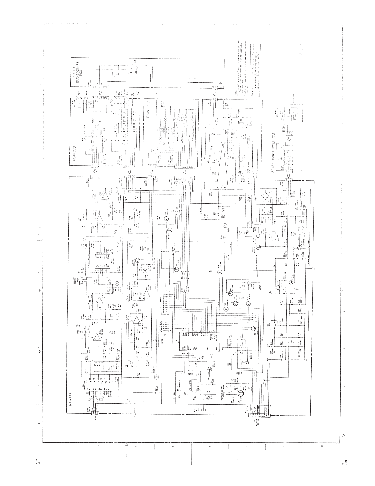
7. Set VR1 on the main PCB to 2250 Hz, +/- 10 Hz (.75 x 3 kHz). Set to 2363 Hz if using a 3150 Hz test tape.
8. Play deck for several minutes and check speed again.
* NOTE: Reasonably priced test tapes are available from your local factory authorized Sony service and parts
center or from the Sony Central Parts Department in Kansas City, MO. Tel: 800 282.2848 Call the Muzak
Technical Service Department at 800 331.3340 if you have difficulty ordering these tapes.
Sony # 7-819-016-11 (P-4-A100, 10 kHz tone for azimuth and EQ)
Sony #7-819-033-11 (WS48-B, 3 kHz tone for W/F and speed)

service parts list
9
REF. # PART NAME
1Rubber Foot....................................................................................
53 Shoulder Screw Pan Head S Tight M3X8............................................
____________________________________________________________________________________________
2MAIN PCB UNIT..............................................................................
51 Pan Head With Spring Washer Screw M3X6.......................................
52 Pan Head With Washer Screw M3X12...............................................
50 Screw Bind B Tight M3X12................................................................
____________________________________________________________________________________________
3Power Trans (S) Assembly........................................................................................................
3-1 Power Trans PCB Unit........................................................................
3-2 Power Trans.....................................................................................
WF-201,
WF-202 Power Amp Fuse, 6.3A.....................................................................
____________________________________________________________________________________________
11 Output Trans (S) Assembly......................................................................................................
11-1 Output Trans PCB Unit.....................................................................
11-2 Output Trans....................................................................................
__________________________________________________________________________________________
4Rear Panel Assembly.........................................................................
4-1 Rear PCB Unit..................................................................................
4-2 AC Inlet Assembly............................................................................
4-3 Fuse 250V 1.6A...............................................................................
5Mecha Unit......................................................................................
5-1 Cassette Mechanism........................................................................
5-2 Eject Arm Returning Spring...............................................................
5-3 Eject Arm.........................................................................................
5-4 Screw..............................................................................................
61 Bind B tight M2.6x6.........................................................................
____________________________________________________________________________________________
10 Front Face Assembly.........................................................................
10-1 Front PCB Unit.................................................................................
10-5 Front Face........................................................................................
10-2 Tape Check Window.........................................................................
10-3 Eject Button......................................................................................
10-4 Front Sheet......................................................................................
62 Bind B tight M2. 6x6........................................................................
____________________________________________________________________________________________
7Housing Assembly............................................................................
7-2 Cassette Spring................................................................................
7-3 Cassette Spring................................................................................
7-4 Eject Screw.......................................................................................
____________________________________________________________________________________________
8Oil Damper......................................................................................
9Harness Earth Wire 80L....................................................................
60 Bind B tight M2x8.............................................................................
PART # UNIT
004-3001-01 4
859-0336-00 4
010-7060-00 1
852-0901-37 3
852-0901-39 1
859-0351-00 2
010-8961-00 1
013-4985-00 1
013-5585-00
013-5585-00 2
010-8962-00 1
013-4117-00 1
011-0080-00 1
010-8960-00 1
011-3222-00 1
013-5517-00 1
010-5016-00 1
014-4203-00 1
015-0219-00 1
016-8406-02 1
859-0408-00 2
850-0101-26 4
011-2061-00 1
010-8959-00 1
016-2057-00 1
016-7013-00 1
016-7811-00 1
017-0503-00 1
850-0101-26 3
011-3224-00 1
015-0021-00 2
016-8404-00 1
015-0335-00 1
014-4834-00 1
909-4000-40 1
850-0101-18 2

11
2901 Third Avenue Suite 400 Seattle, WA 98121 800 223.0686 www.muzak.com
creating experiences with audio architecture
CP-2500-03
REF. # PARTS NAME
12 PC Support......................................................................................
13 Wire Saddle.....................................................................................
14 Cable Clip.......................................................................................
15 Main Chassis...................................................................................
__________________________________________________________________________________________________________
54 Bind S tight M3x6.............................................................................
55 Bind S tight M4x6.............................................................................
56 Bind B tight M3x10 with Knock.........................................................
57 Bind S tight M3x6 Knock..................................................................
58 Bind F M3x5....................................................................................
6Cassette Door Assembly...................................................................
16 Top Cover Assembly..........................................................................
16-1 Caution Label..................................................................................
16-2 Rain Label.......................................................................................
16-3 CSA Warning Label..........................................................................
16-4 Fuse Label 2....................................................................................
16-5 Bonnet.............................................................................................
17 Volume Knob...................................................................................
59 Bind Small Black M4x6 Knock..........................................................
Cleaning Kit.....................................................................................
Attachment Assembly........................................................................
Fuse 250V 1.6A...............................................................................
AC Cord..........................................................................................
Patch Cord......................................................................................
Muzak Cleaning Liquid Label...........................................................
Muzak Warranty Card......................................................................
Case...............................................................................................
Cushion L........................................................................................
Cushion R........................................................................................
Master Carton.................................................................................
Wrap Label......................................................................................
PART # UNIT
014-3112-00 4
014-9008-00 1
014-9009-00 2
016-0127-00 1
850-0201-37 10
850-0201-49 3
859-0322-00 4
859-0167-00 2
859-0343-00 2
011-3223-00 1
011-3225-00 1
007-0216-02 1
007-0237-01 1
007-0247-02 1
007-0298-00 1
016-0216-00 1
016-7812-00 1
859-0175-01 6
007-1701-00 1
011-8049-00 1
013-5517-00 1
013-3079-00 1
013-3115-00 1
017-0273-00 1
017-0307-10 1
601-0117-00 1
602-0053-00 1
602-0054-00 1
602-0029-00 1
609-0028-00 1
Other manuals for CP-2500
1
Other Muzak Cassette Player manuals