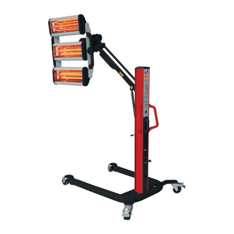
MW TOOLS LD2 User manual

M1.2.LD2.NLFREN - 05122017
HANDLEIDING - MODE D’EMPLOI - MANUAL
LD2 (829000301)
Infrarood lakdroger
Sécheur de peinture infrarouge
Infrared paint dryer
P.02 Gelieve te lezen en voor later gebruik bewaren
P.06 Veuillez lire et conserver pour consultation ultérieure
P.10 Please read and keep for future reference
FR
EN
NL
copyrighted document - all rights reserved by FBC

M1.2.LD2.NLFREN - 05122017
2
NL
1 Veiligheidsvoorschriften
• Dit toestel is geschikt voor het drogen en uitharden van verf. Houd een veilige afstand tussen de zender en het paneel. Een
onjuist onderhoud kan schade aan de verfopperklakte veroorzaken.
• De installatie en het onderhoud moeten door gekwaliceerd personeel uitgevoerd worden.
• Het systeem is ontworpen voor gemakkelijke installatie, lage operationele kosten en een minimum aan onderhoud. De
garantie geldt niet voor schade aan de lamp als gevolg van een misbruik of onjuist gebruik.
• Ontkoppel het toestel van de stroomtoevoer, als het voor een lange periode niet gebruikt wordt.
• Tijdens het gebruik, mag de lamp niet loodrecht naar de grond gericht worden. Dit verkort de levensduur van de lamp.
• Schakel het toestel uit na gebruik. Plaat het toestel op een veilige plaats, om beschadiging van de lampen te voorkomen.
2 Technische gegevens
Model LD2
Stroomtoevoer 230 V
Input vermogen 2 x 1000 W
Uitharding oppervlakte 800 x 800 mm
Temperatuur 30 - 100 °C
Timer 0 - 60 min.
Lichtsterkte 10 - 100 %
Afmetingen 580 x 500 x 1600 mm
Netto gewicht 19 kg
3 Installatie
The shortwave infrared curing lamp is divided into 3 parts (a base, a frame and a cassette)
1) Installation of the base:
a. Open the packing of the base.
b. Install the four wheels on the base and tighten up the screws.
Usually, the wheels with brakes are mounted on the rear of the base.
2) Installation of the frame:
a. Open the packing of the frame.
b. Put the column onto the top of the base, line up the screw holes and tighten up
with screws.
3) Installation of the cassette:
a. Open the packaging of cassette with care.
b. Connect cassette with holder and tighten up by screws.
c. Connect control wires and adjust the angle of the lamps.
Page 3
1. Main switch
2. Control box
3. Cassette
4. Cassette
5. Holder
6. Column
7. Base
8. Caster
3. Installation
1
2
3
4
5
6
7
8
1. Hoofdschakelaar
2. Bedieningskast
3. Cassette
4. Cassette
5. Houder
6. Kolom
7. Basis
8. Wiel
copyrighted document - all rights reserved by FBC

M1.2.LD2.NLFREN - 05122017
3
NL
De lakdroger bestaat uit 3 delen (de basis, de kolom en een cassette).
1. Installatie van de basis.
a. Neem de basis uit de verpakking.
b. Monteer de 4 wielen op de basis, en bevestig met de schroeven. De wielen met rem worden gewoonlijk aan de
achterkant gemonteerd.
2. Installatie van de kolom.
a. Neem de kolom uit de verpakking.
b. Plaats de kolom verticaal boven de basis. De gaten moeten met elkaar overeenkomen. Schroef de kolom op de basis
vast.
c. Monteer de steunarm voor de cassette op de kolom.
d. Monteer de hijsbeugel op de kolom. Deze controleert de opwaartse en neerwaartse bewegingen van de cassette.
3. Installatie van de cassette.
a. Neem de cassette voorzichtig uit de verpakking.
b. Monteer de cassette op de houder, en bevestig met de schroeven.
c. Sluit de bedieningskabels aan, en stel de hoek van de cassette in.
4 Bedieningselementen
1. Vermogensinstelling
2. Tijdsinstelling
Page 4
1.
2.
Power Adjustment
Time Adjustment
AC2 20V-24 0V 50/60 Hz
00
10
20
30
40
50
60
ON
TIME CONTROL SYSTEM
POWER CONTROL SYSTEM
1
2
10
20
30
40
50
60
70
80
80
60
00
100
90
4. Controls
copyrighted document - all rights reserved by FBC

M1.2.LD2.NLFREN - 05122017
4
NL
Page 5
2
1. Connect electricity supply. Make sure that the supply cable is at least 4mm at 220V
Note: Make sure that the facility supply voltage and frequency are the same as shown on
the equipment name plate.
2. Connect to power supply AC 220V. Switch on the equipment. The LED display will show the
normal voltage as 220V.
3. Set time and power according to the requirements of paint used for curing to achieve the
best curing result (usually, the values are set at 15 mins in time and 70% in power).
4. Adjust the distance from heat source to paint surface (usually, keeping a distance of
45cm from the paint surface is the best).
5. Protect the lamp against shocks and vibrations even when it is cold.
6. During the curing process, the paint surface must be clean without water and impurities.
7. Preferably do not touch quartz with bare hands. If grease or chemical compound have
been deposited on quartz, simply clean before lighting with cloth moistened with alcohol.
Install machine
Data displayed
on screen
Set up temperature
Switch off
Connect input
power
Switch on
30-60cm
ON
OFF
Set up time
ON
OFF
Heat source parallel
to paint surface at a
distance of 30-60cm
00
10
20
30
40
50
60
ON
5. Operation
Installeer het toestel Sluit het netsnoer aan Schakel het toestel in
Digitale display Stel de tijd in
Houd de warmtebron parallel
met de verfoppervlakte, en op
45 cm afstand
Schakel het toestel uit na
uitharding
Stel de temperatuur in
5 Bediening
1. Sluit het netsnoer aan (kabel van tenminste 4 mm²).
2. Schakel het toestel in, de LED display toont de normale spanning 220 V.
3. Bepaal het vermogen en de temperatuur volgens het type verf (gewoonlijk worden de waarden 15 minuten en 70%
vermogen ingesteld).
4. Voor een optimaal resultaat, moet de zender parallel met de verfoppervlakte geplaatst worden.
5. Stel de afstand tussen de warmtebron en het verfoppervlakte in. Een afstand van 45 cm is ideaal.
6. Bescherm de lamp tegen schokken en trillingen, zelfs wanneer deze koud is.
7. Tijdens het droogproces, moet de verfoppervlakte schoon zijn, vrij van water en onzuiverheden.
8. Raak de kwarts bij voorkeur niet met blote handen. Als er vet of een chemische component op de kwarts afgezet is, reinig
deze voor gebruik, gewoon met een doek met alcohol.
copyrighted document - all rights reserved by FBC

M1.2.LD2.NLFREN - 05122017
5
NL
6 Problemen oplossen
Probleem Oorzaak Oplossing
De lampen werken niet Lampen beschadigd Controleer de lampen
Lampen niet correct aangesloten Controleer de aansluitingen
SCR beschadigd Controleer de SCR
De lampen schakelen niet uit SCR beschadigd Controleer de SCR
De display toont niets, of niet alles Platte kabel in de printplaat
beschadigd Controleer de platte kabel
Display beschadigd Controleer de display
De tijd en de temperatuur kunnen
niet ingesteld worden Potentiometer beschadigd Controleer of de potentiometer correct
werkt
Timer beschadigd Controleer of de timer correct werkt
7 De lampen vervangen
1. Bereid de vervangingscassette voor.
2. Verwijder het rooster van de cassette.
3. Verwijder de plaat aan beide uiteinden van de cassette.
4. Verwijder de vaste plaat aan beide uiteinden van de cassette.
5. Draai de bevestigingsschroeven los, en snijd de verbindingen af. De lamp kan nu vervangen worden.
6. Voer de voorgaande stappen in omgekeerde volgorde uit, om de nieuwe lamp te installeren.
2. Lamp Tube Replacement
(1)
(2)
(3)
(4)
(5)
(6)
1. Prepare cassette for replacement
2. Remove the grille of cassette
3. Remove the plates from both
ends of the cassette
4. Remove the fixed plates from
both ends of the cassette
5. Loosen fixed screws and cut
off connections, the lamp can
be replaced
6. Reverse the steps above to install
the new lamp
Page 7
6. Troubleshooting
copyrighted document - all rights reserved by FBC

6
M1.2.LD2.NLFREN - 05122017
FR
1 Consignes de sécurité
• Cet appareil est conçu pour le séchage et le durcissement de peinture. Maintenez une distance de sécurité entre l’émetteur
et le panneau. Un entretien inadéquat peut endommager la surface de la peinture.
• L’installation et l’entretien doivent être effectués par du personnel qualié.
• Le système est conçu pour une installation facile, des coûts d’utilisation faible et un entretien minimum. La garantie ne
couvre pas les dommages à la lampe dus à une utilisation inadéquate.
• Débranchez l’alimentation électrique si l’appareil n’est pas utilisé pendant une longue période.
• La lampe ne peut pas être orientée perpendiculairement au sol quand l’appareil fonctionne. Cela raccourcis sa durée de
vie.
• Éteignez l’appareil après utilisation. Placez l’appareil dans un endroit sûr, pour éviter d’endommager les lampes.
2 Données techniques
Modèle LD2
Alimentation électrique 230 V
Puissance d’entrée 2 x 1000 W
Surface de durcissement 800 x 800 mm
Température 30 - 100 °C
Minuterie 0 - 60 min.
Intensité lumineuse 10 - 100 %
Dimensions 580 x 500 x 1600 mm
Poids net 19 kg
3 Installation
The shortwave infrared curing lamp is divided into 3 parts (a base, a frame and a cassette)
1) Installation of the base:
a. Open the packing of the base.
b. Install the four wheels on the base and tighten up the screws.
Usually, the wheels with brakes are mounted on the rear of the base.
2) Installation of the frame:
a. Open the packing of the frame.
b. Put the column onto the top of the base, line up the screw holes and tighten up
with screws.
3) Installation of the cassette:
a. Open the packaging of cassette with care.
b. Connect cassette with holder and tighten up by screws.
c. Connect control wires and adjust the angle of the lamps.
Page 3
1. Main switch
2. Control box
3. Cassette
4. Cassette
5. Holder
6. Column
7. Base
8. Caster
3. Installation
1
2
3
4
5
6
7
8
1. Interrupteur principal
2. Boîtier de commande
3. Cassette
4. Cassette
5. Support
6. Colonne
7. Base
8. Roue
copyrighted document - all rights reserved by FBC

7
M1.2.LD2.NLFREN - 05122017
FR
Le sécheur de peinture infrarouge se compose de 3 parties (la base, la colonne et une cassette).
1. Installation de la base.
a. Déballez la base.
b. Installez les 4 roues sur la base et xez-les avec les vis. Les roues avec frein sont habituellement montées à l’arrière.
2. Installation de la colonne.
a. Déballez la colonne.
b. Placez la colonne verticalement sur le haut de la base, en faisant correspondre les trous, et vissez la colonne sur la base.
c. Montez le bras de support de la cassette sur la colonne.
d. Montez la barre de levage sur la colonne. Celle-ci contrôle les mouvements ascendants ou descendants de la cassette.
3. Installation de la cassette.
a. Déballez la cassette avec soin.
b. Montez la cassette sur le support, et xez avec les vis.
c. Branchez les câbles de la commande et réglez l’angle de la cassette.
4 Commandes
1. Réglage de la puissance
2. Réglage du temps
Page 4
1.
2.
Power Adjustment
Time Adjustment
AC2 20V-24 0V 50/60Hz
00
10
20
30
40
50
60
ON
TIME CONTROL SYSTEM
POWER CONTROL SYSTEM
1
2
10
20
30
40
50
60
70
80
80
60
00
100
90
4. Controls
copyrighted document - all rights reserved by FBC

8
M1.2.LD2.NLFREN - 05122017
FR
Page 5
2
1. Connect electricity supply. Make sure that the supply cable is at least 4mm at 220V
Note: Make sure that the facility supply voltage and frequency are the same as shown on
the equipment name plate.
2. Connect to power supply AC 220V. Switch on the equipment. The LED display will show the
normal voltage as 220V.
3. Set time and power according to the requirements of paint used for curing to achieve the
best curing result (usually, the values are set at 15 mins in time and 70% in power).
4. Adjust the distance from heat source to paint surface (usually, keeping a distance of
45cm from the paint surface is the best).
5. Protect the lamp against shocks and vibrations even when it is cold.
6. During the curing process, the paint surface must be clean without water and impurities.
7. Preferably do not touch quartz with bare hands. If grease or chemical compound have
been deposited on quartz, simply clean before lighting with cloth moistened with alcohol.
Install machine
Data displayed
on screen
Set up temperature
Switch off
Connect input
power
Switch on
30-60cm
ON
OFF
Set up time
ON
OFF
Heat source parallel
to paint surface at a
distance of 30-60cm
00
10
20
30
40
50
60
ON
5. Operation
Installez l’appareil Branchez le câble
d’alimentation Allumez l’appareil
Afchage digital Réglez la température
Maintenez la source de chaleur
parallèlement et à 45 cm de la
surface peinte
Éteignez l’appareil après
durcissement
Réglez le temps
5 Utilisation
1. Branchez le câble d’alimentation (prendre un câble d’au moins 4 mm²).
2. Allumez la machine, l’écran LED afche la tension normale de 220 V.
3. Déterminez le temps et la puissance en fonction du type de peinture (habituellement, les valeurs de 15 minutes et 70% de
puissance sont réglées).
4. Pour un résultat optimal, l’émetteur doit être placé parallèlement à la surface peinte.
5. Réglez la distance entre la source de chaleur et la surface peinte. Une distance de 45 cm est idéale.
6. Protégez la lampe des chocs et des vibrations, même quand elle est froide.
7. Pendant le processus de durcissement, la surface de la peinture doit être propre, sans eau ni impuretés.
8. Ne touchez pas le quartz à mains nues. Si de la graisse ou un composé chimique s’est déposé sur le quartz, nettoyez-le
simplement avant utilisation, avec un chiffon imbibé d’alcool.
copyrighted document - all rights reserved by FBC

9
M1.2.LD2.NLFREN - 05122017
FR
6 Résolution des pannes
Panne Cause Solution
Les lampes ne fonctionnent pas Lampes endommagées Vériez les lampes
Les lampes ne sont pas bien branchées Vériez les branchements
SCR endommagé Contrôlez le SCR
Les lampes ne s’éteignent pas SCR endommagé Contrôlez le SCR
L’écran n’afche rien ou n’afche
que partiellement Câble plat débranché dans la carte du
circuit imprimé Contrôlez le câble plat
Écran endommagé Contrôlez l’écran
Le temps et la température ne
peuvent pas être réglés Potentiomètre endommagé Contrôlez si le potentiomètre
fonctionne correctement
Minuterie endommagée Contrôlez si la minuterie fonctionne
correctement
7 Remplacer les lampes
1. Préparez la cassette de rechange.
2. Enlevez la grille de la cassette.
3. Enlevez les plaque aux deux extrémités de la cassette.
4. Enlevez la plaque xe aux deux extrémités de la cassette.
5. Desserrez les vis de xation et coupez les connexions. La lampe peut à présent être remplacée.
6. Effectuez les étapes précédentes en sens inverse pour installer la nouvelle lampe.
2. Lamp Tube Replacement
(1)
(2)
(3)
(4)
(5)
(6)
1. Prepare cassette for replacement
2. Remove the grille of cassette
3. Remove the plates from both
ends of the cassette
4. Remove the fixed plates from
both ends of the cassette
5. Loosen fixed screws and cut
off connections, the lamp can
be replaced
6. Reverse the steps above to install
the new lamp
Page 7
6. Troubleshooting
copyrighted document - all rights reserved by FBC

10
M1.2.LD2.NLFREN - 05122017
EN
1 Safety instructions
• This equipment is designed for paint curing application. Keep a safe distance between emitter and panel. Improper
servicing can cause paint surface damage.
• Installation and service must be performed by a qualied installer or service agent.
• The system has been designed for easy installation, low operating costs and minimal maintenance. The warranty does not
cover lamp tube defects resulting from misuse or improper operation.
• Disconnect power source when the equipment is not in use for a long period.
• The lamp tube should not be perpendicular to the ground when the equipment is operating. Otherwise, it will shorten the
life of the lamp tube.
• Turn off the equipment after using. Place the equipment in a safe place to avoid damage to the lamp tube.
2 Technical parameters
Model LD2
Power supply 230 V
Input power 2 x 1000 W
Curing area 800 x 800 mm
Temperature 30 - 100 °C
Timer 0 - 60 min.
Light intensity 10 - 100 %
Dimensions 580 x 500 x 1600 mm
Net weight 19 kg
3 Installation
The shortwave infrared curing lamp is divided into 3 parts (a base, a frame and a cassette)
1) Installation of the base:
a. Open the packing of the base.
b. Install the four wheels on the base and tighten up the screws.
Usually, the wheels with brakes are mounted on the rear of the base.
2) Installation of the frame:
a. Open the packing of the frame.
b. Put the column onto the top of the base, line up the screw holes and tighten up
with screws.
3) Installation of the cassette:
a. Open the packaging of cassette with care.
b. Connect cassette with holder and tighten up by screws.
c. Connect control wires and adjust the angle of the lamps.
Page 3
1. Main switch
2. Control box
3. Cassette
4. Cassette
5. Holder
6. Column
7. Base
8. Caster
3. Installation
1
2
3
4
5
6
7
8
copyrighted document - all rights reserved by FBC

11
M1.2.LD2.NLFREN - 05122017
EN
The shortwave infrared curing lamp is divided into 3 parts (a base, a column and a cassette).
1. Installation of the base.
a. Open the packing of the base.
b. Install the four wheels on the base respectively and tighten up the screws. Usually, the wheels with brakes should be
mounted on the rear of the base.
2. Installation of the column.
a. Open the packing of the column.
b. Put the column vertically on the top of the base, directly engage the screw holes and tighten up using the screws.
c. Connect the support arm with the column for supporting the cassette.
d. Connect the lifter with the column to control the up and down movement of the cassette.
3. Installation of the cassette.
a. Open the packing of the cassette with care.
b. Connect cassette with holder and tighten up with the screws.
c. Connect control wires and adjust the angle of cassette.
4 Controls
1. Power adjustment
2. Time adjustment
Page 4
1.
2.
Power Adjustment
Time Adjustment
AC2 20V-24 0V 50/60 Hz
00
10
20
30
40
50
60
ON
TIME CONTROL SYSTEM
POWER CONTROL SYSTEM
1
2
10
20
30
40
50
60
70
80
80
60
00
100
90
4. Controls
copyrighted document - all rights reserved by FBC

12
M1.2.LD2.NLFREN - 05122017
EN
5 Operation
1. Connect input power cord (should be no less than 4 mm² cord).
2. Switch on the machine, the LED display will show the normal voltage is 220 V.
3. Set time and power according to the requirements of paint used for curing to achieve the best curing result (usually, the
values are set at 15 min in time and 70% in power).
4. To achieve the best curing result, the lamp should be parallel with the paint surface.
5. Adjust the distance from heat source to the paint surface. Usually, a distance of 45 cm is the best.
6. Protect the lamp against shocks and vibrations even when it is cold.
7. When paint curing, the paint surface must be clean, without water and impurities.
8. Preferably do not touch quartz with bare hands. If grease or chemical compound have been deposited on quartz, simply
clean before lighting with cloth moistened with alcohol.
Page 5
2
1. Connect electricity supply. Make sure that the supply cable is at least 4mm at 220V
Note: Make sure that the facility supply voltage and frequency are the same as shown on
the equipment name plate.
2. Connect to power supply AC 220V. Switch on the equipment. The LED display will show the
normal voltage as 220V.
3. Set time and power according to the requirements of paint used for curing to achieve the
best curing result (usually, the values are set at 15 mins in time and 70% in power).
4. Adjust the distance from heat source to paint surface (usually, keeping a distance of
45cm from the paint surface is the best).
5. Protect the lamp against shocks and vibrations even when it is cold.
6. During the curing process, the paint surface must be clean without water and impurities.
7. Preferably do not touch quartz with bare hands. If grease or chemical compound have
been deposited on quartz, simply clean before lighting with cloth moistened with alcohol.
Install machine
Data displayed
on screen
Set up temperature
Switch off
Connect input
power
Switch on
30-60cm
ON
OFF
Set up time
ON
OFF
Heat source parallel
to paint surface at a
distance of 30-60cm
00
10
20
30
40
50
60
ON
5. Operation
45 cm
copyrighted document - all rights reserved by FBC

13
M1.2.LD2.NLFREN - 05122017
EN
6 Troubleshooting
Problem Cause Solution
Lamp tube does not work Lamp tube damaged Check lamp tube
Lamp tube not plugged in Check connections
SCR damaged Check SCR
Lamp tube does not turn off SCR damaged Check SCR
Digital display is blank or is
incomplete Unplugged at wire in circuit board Check at wire
Digital display is damaged Check digital display
Time and temperature cannot be
adjusted Potentiometer damaged Check whether the potentiometer is in
proper working conditions
Timer damaged Check whether the timer is in proper
working conditions
7 Lamp tube replacement
1. Prepare the cassette for replacement.
2. Remove the grille of the cassette.
3. Remove the plates form both ends of the cassette.
4. Remove the xed plate from both ends of the cassette.
5. Loosen xed screws and cut off connections, the lamp can be replaced.
6. Reverse the steps above to install the new lamp.
2. Lamp Tube Replacement
(1)
(2)
(3)
(4)
(5)
(6)
1. Prepare cassette for replacement
2. Remove the grille of cassette
3. Remove the plates from both
ends of the cassette
4. Remove the fixed plates from
both ends of the cassette
5. Loosen fixed screws and cut
off connections, the lamp can
be replaced
6. Reverse the steps above to install
the new lamp
Page 7
6. Troubleshooting
copyrighted document - all rights reserved by FBC

14
M1.2.LD2.NLFREN - 05122017
NL
FR
EN
8 Onderdelen
8 Pièces détachées
8 Spare parts
copyrighted document - all rights reserved by FBC
15
M1.2.LD2.NLFREN - 05122017
NL
FR
EN
9 Schakelschema
9 Schéma électrique
9 Circuit diagram
Page 8
8. Circuit Diagram
Ov er -C urr ent P rote c tion S w itc h
P ow e r S w it c h
A C 2 20V
N
PC B
1234
K1
K2
G1
G2
G2 K2G1K1
K1 G1 K2G2
P ow er S w itc h
Temperature Regulation TIMER
A LAMP
B LAMP
AC 230V
copyrighted document - all rights reserved by FBC

16
M1.2.LD2.NLFREN - 05122017
Fabrikant/Invoerder
Fabricant/Importateur
Manufacturer/Retailer
Verklaart hierbij dat het volgende product :
Déclare par la présente que le produit suivant :
Hereby declares that the following product :
Product
Produit
Product
Infrarood lakdroger
Sécheur de peinture infrarouge
Infrared paint dryer
Order nr. :
Geldende CE-richtlijnen
Normes CE en vigueur
Relevant EU directives
2014/35/EU
EN 60598-2-4:1997
EN 60598-1:2015
EN 62493:2015
2014/30/EU
EN 61000-6-4:2007+A1:2011
EN 61000-6-2:2005
EN 61000-3-2:2014
EN 61000-3-3: 2013
Overeenstemt met de bestemming van de hierboven aangeduide richtlijnen - met inbegrip van deze betreffende het
tijdstip van de verklaring der geldende veranderingen.
Répond aux normes générales caractérisées plus haut, y compris celles dont la date correspond aux modications en
vigueur.
Meets the provisions of the aforementioned directive, including, any amendments valid at the time of this statement.
Vynckier Tools sa
Avenue Patrick Wagnon, 7
ZAEM de Haureu
B-7700 Mouscron
10 EG conformiteitsverklaring
10 Déclaration de conformité CE
10 EC declaration of conformity
LD2 (829000301)
FR
EN
NL
Bart Vynckier, Director
VYNCKIER TOOLS sa
Mouscron, 05/12/2017
copyrighted document - all rights reserved by FBC
This manual suits for next models
1
Table of contents
Other MW TOOLS Dryer manuals
Popular Dryer manuals by other brands

GE
GE Spacemaker DSKP233 owner's manual

GE
GE GTD45GASJ Dimensions and installation information

Hotpoint
Hotpoint TCFM 70C Futura Instruction booklet

Domus
Domus DTA-DTP-11 user manual

Admiral
Admiral 3RAED3005 User instructions

Dexter Laundry
Dexter Laundry T-80 Operators manual installation & operation instructions

Beko
Beko DCY 7402 GB5 user manual

Alliance Laundry Systems
Alliance Laundry Systems Drying Tumblers none Maintenance Guide

AEG
AEG LAVATHERM 56800 User information

Whirlpool
Whirlpool LGR4634JQ0 installation instructions

Maytag
Maytag Neptune MDE9700AYM Use & care guide

Samsung
Samsung DVE45T6000 Series user manual