8
M1.2.LD3P.NLFREN - 05122017
FR
5 Utilisation
1. Branchez le câble d’alimentation (prendre un câble de cuivre d’au moins 4 mm²).
2. Allumez la machine, l’écran afche des chiffres.
3. Sélectionnez «Routine» ou «Pulse».
4. Déterminez la température et le temps en fonction du type de peinture. L’écran afche des chiffres. Le durcissement par
impulsion donne un résultat plus brillant.
5. Pour un résultat optimal, l’émetteur doit être placé parallèlement à la surface peinte.
6. Réglez la distance entre la source de chaleur et la surface peinte. Une distance de 30-50 cm est idéale.
7. Pendant le processus de durcissement, la surface de la peinture doit être propre, sans eau ni impuretés.
8. Éteignez l’appareil après utilisation. Placez l’appareil dans un endroit sûr, pour éviter d’endommager les lampes.
5. Operation
2
1. Connect input power cord (should be no less than 4mm copper cord).
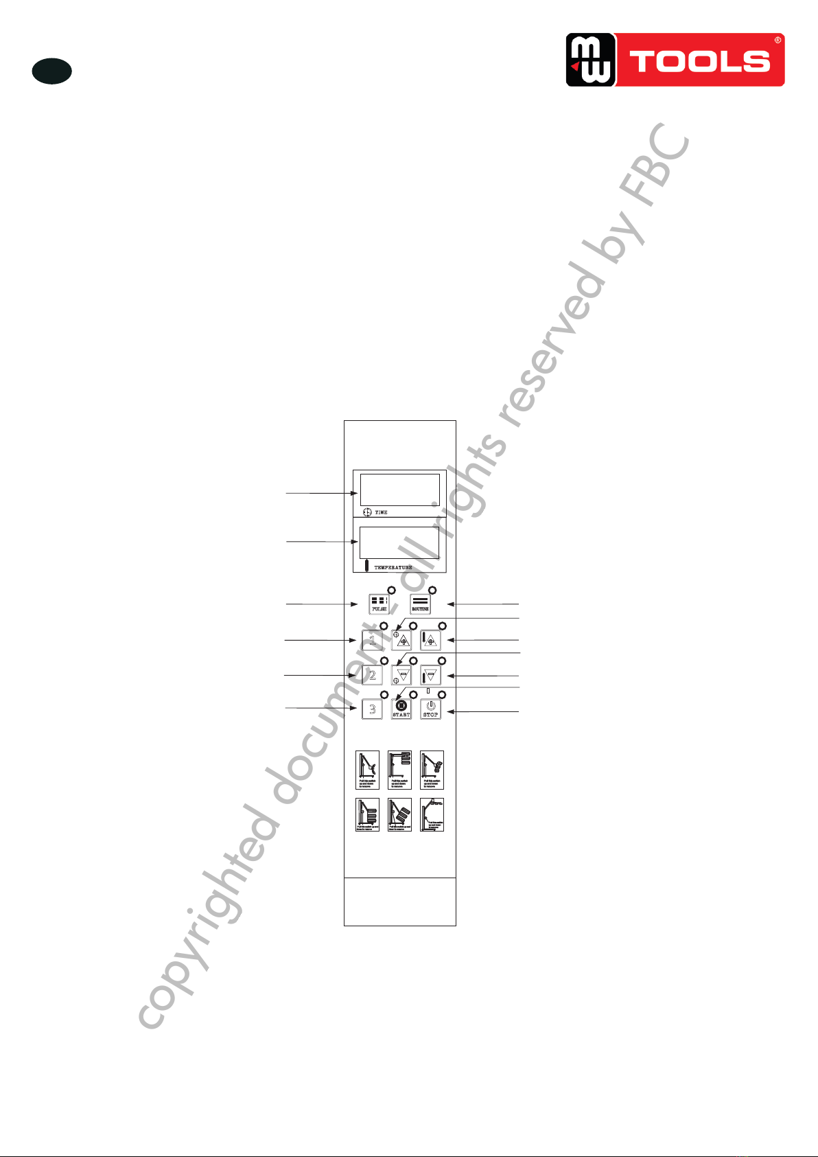
2. Turn on the machine, digital displays will show figures.
3. Select “Routine” or “Pulse”.
4. Set temperature and time according to the requirements of paint being cured. The
display will show data. Pulse curing helps to achieve more lustrous results.
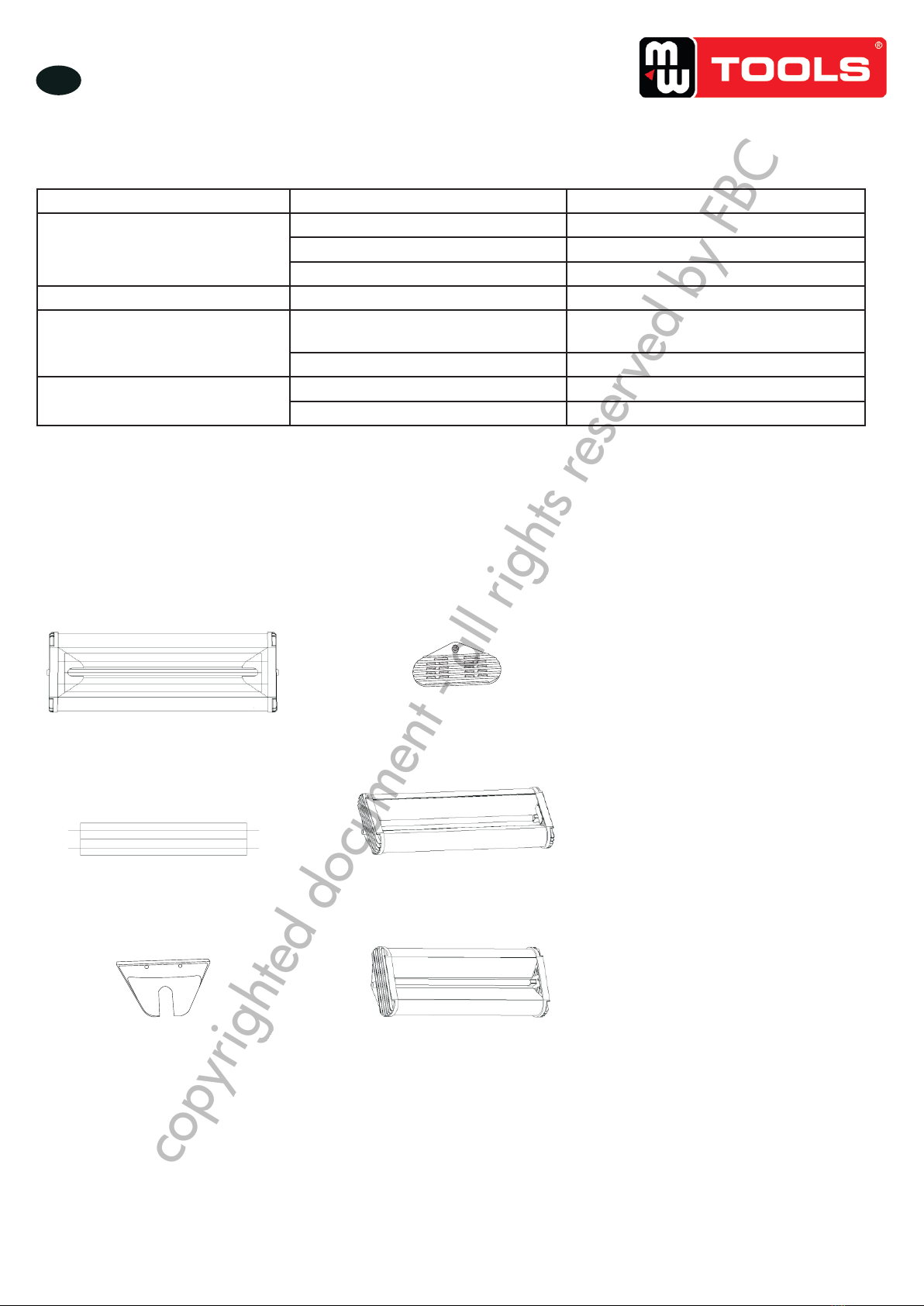
5. To achieve the best curing result, the lamp should be parallel with the paint surface.
6. Adjust the distance from heat source to the paint surface. Usually, a distance of 30-50cm
is best.
7. When paint curing, the paint surface must be clean, without water and impurities.
8. Turn off the equipment after using. Place the equipment in a safe place to avoid damage
to the lamp tube.
30-60cm
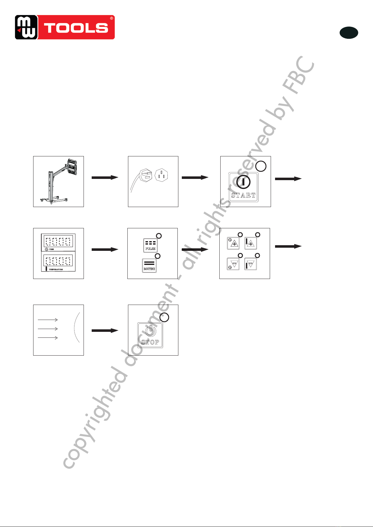
Install machine Connect input power Switch on
Digital display data Select “Pulse” or
“Routine”
Set “ Temperature”
and “Time”
Keep heat source parallel
to paint surface a distance
of 30-60cm
Switch off the machine
after curing
Installez l’appareil Branchez le câble
d’alimentation Allumez l’appareil
Afchage digital Sélectionnez «Pulse» ou
«Routine» Réglez la température et
le temps
Maintenez la source de chaleur
parallèlement et à 30-60 cm de
la surface peinte
Éteignez l’appareil après
durcissement
copyrighted document - all rights reserved by FBC