10
NL
M1.1.MWM1200.NLFREN 23082018
4�3 Weerstand meten
1. Sluit de zwarte testkabel aan de COM aansluiting aan en de rode kabel aan de VΩHz aansluiting.
2. Draai de draaiknop naar , et de display zal “OL” tonen.
3. Zet de sensoren op de gewenste testpunten van het circuit, om de weerstand te meten.
4. Lees de gemeten weerstand op de display.
*Koppel de stroomtoevoer van het circuit los en ontlast alle condensatoren voordat u de weerstand test�
*Voer bij deze instelling geen spanning in�
4�4 Continuïteitstest
1. Sluit de zwarte testkabel aan de COM aansluiting aan en de rode kabel aan de VΩHz aansluiting.
2. Draai de draaiknop naar , druk op SELECT om naar de Continuïteit modus te gaan.
3. Zet de sensoren op de gewenste testpunten van het circuit.
4. Het ingebouwde geluidssignaal zal een pieptoon geven wanneer de weerstand minder dan 50 Ω bedraagt, wat op
kortsluiting duidt.
*Voer bij deze instelling geen spanning in�
4�5 Diodetest
5. Sluit de zwarte testkabel aan de COM aansluiting aan en de rode kabel aan de VΩHz aansluiting.
6. Draai de draaiknop naar , druk op SELECT tweemaal op naar de Diode modus over te schakelen.
7. Sluit de rode sensor aan de anodezijde aan en de zwarte sensor aan de kathodezijde van de te testen diode.
8. Lees de waarde van de polarisatiespanning af in de richting die op de display weergegeven wordt.
9. Als de polariteit van de testkabel omgekeerd wordt met de polariteit van de diode, of als de diode gebroken is, geen de
display “OL” weer.
*Koppel de stroomtoevoer van het circuit los en ontlast alle condensatoren voordat u de diode test�
*Voer bij deze instelling geen spanning in�
4�6 De capaciteit meten
1. Sluit de zwarte testkabel aan de COM aansluiting aan en de rode kabel aan de VΩHz aansluiting.
2. Draai de draaiknop naar , druk op SELECT driemaal om naar de Capaciteit modus over te schakelen.
3. Sluit de rode sensor aan de anodezijde aan en de zwarte sensor aan de kathodezijde van de te testen condensator.
4. Lees de waarde van de gemeten capaciteit op de display wanneer de aezing gestabiliseerd is.
*Koppel de stroomtoevoer van het circuit los en ontlast alle condensatoren voordat u de capaciteit test�
4�7 De frequentie meten
1. Sluit de zwarte testkabel aan de COM aansluiting aan en de rode kabel aan de VΩHz aansluiting.
2. Draai de draaiknop naar , druk op SELECT eenmaal, om naar de AC V modus te gaan druk vervolgens op Hz/Duty
eenmaal om naar de Frequentie modus te gaan (geldig voor een lage frequentie met een hoge spanning), of draai de
draaiknop naar HZ (geldig voor een hoge frequentie met een lage spanning).
3. Zet de sensoren op de gewenste testpunten.
4. Lees de waarde van de gemeten frequentie op de display.
Measure Resistance
1. Connect the black test lead to the COM
Terminal and the test lead to the VΩHz
Terminal.
2. Turn the rotary switch to ,and the display
will show “ ”.
3. Touch the probes to the desired test points of
the circuit to measure the resistance.
4. Read the measured resistance on the display.
Test for Continuity
1. Connect the black test lead to the COM
Terminal and the red lead to the VΩHz
Terminal.
2. Turn the rotary switch to , press SELECT
once to toggle to the Continuity Mode.
3. Touch the probes to the desired test points of
the circuit.
13
*Disconnect circuit power and discharge all
capacitors before you test resistance.
*Do not input voltage at this setting.
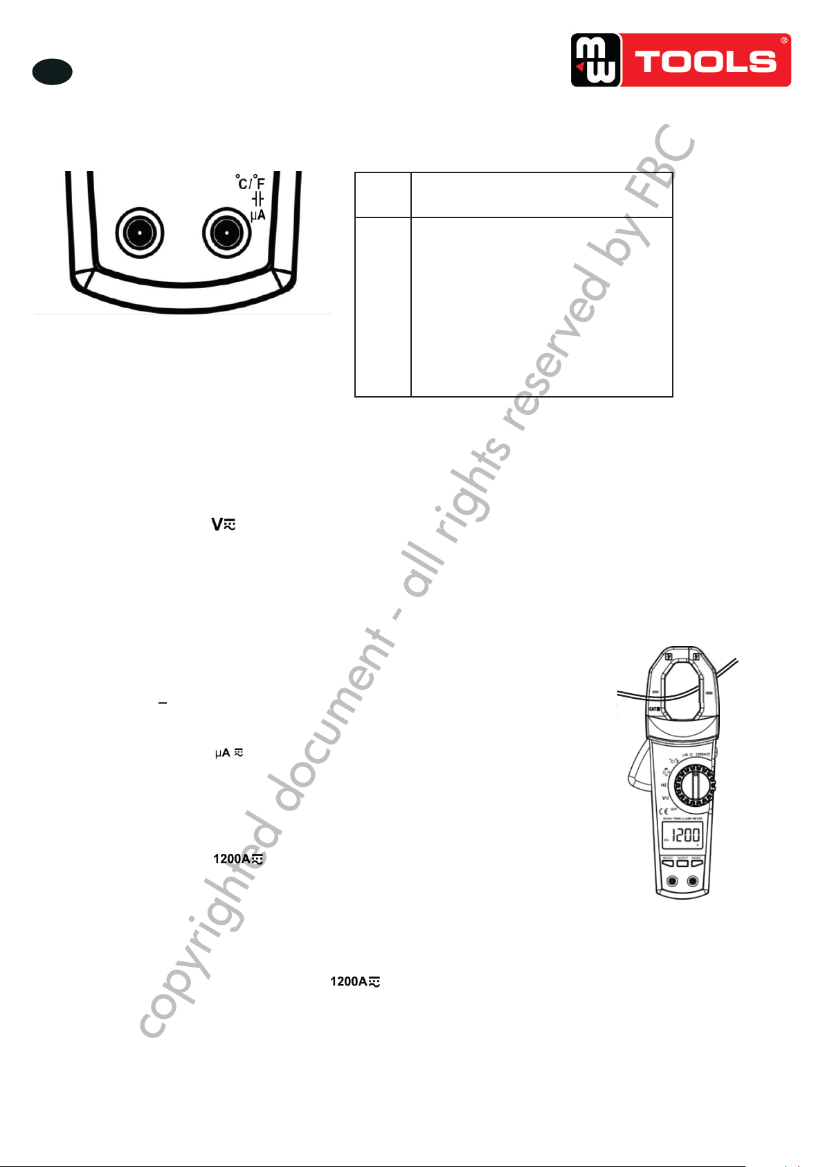
Selects alternate measurement modes on a
rotary switch setting, including:
1. DC V/AC V
2. Resistance/Continuity/Diode/Capacitance
3. Celsius/Fahrenheit
4. DC μA/AC μA
5. DC A/AC A
When the rotary switch is at , push
SELECT once to toggle to AC V testing
mode, then push this button to enter
Frequency/Duty Cycle (with high voltage)
testing mode.
When the rotary switch is at , push this
button to enter Frequency/Duty Cycle (with
low voltage) testing mode.
③
④
copyrighted document - all rights reserved by FBC