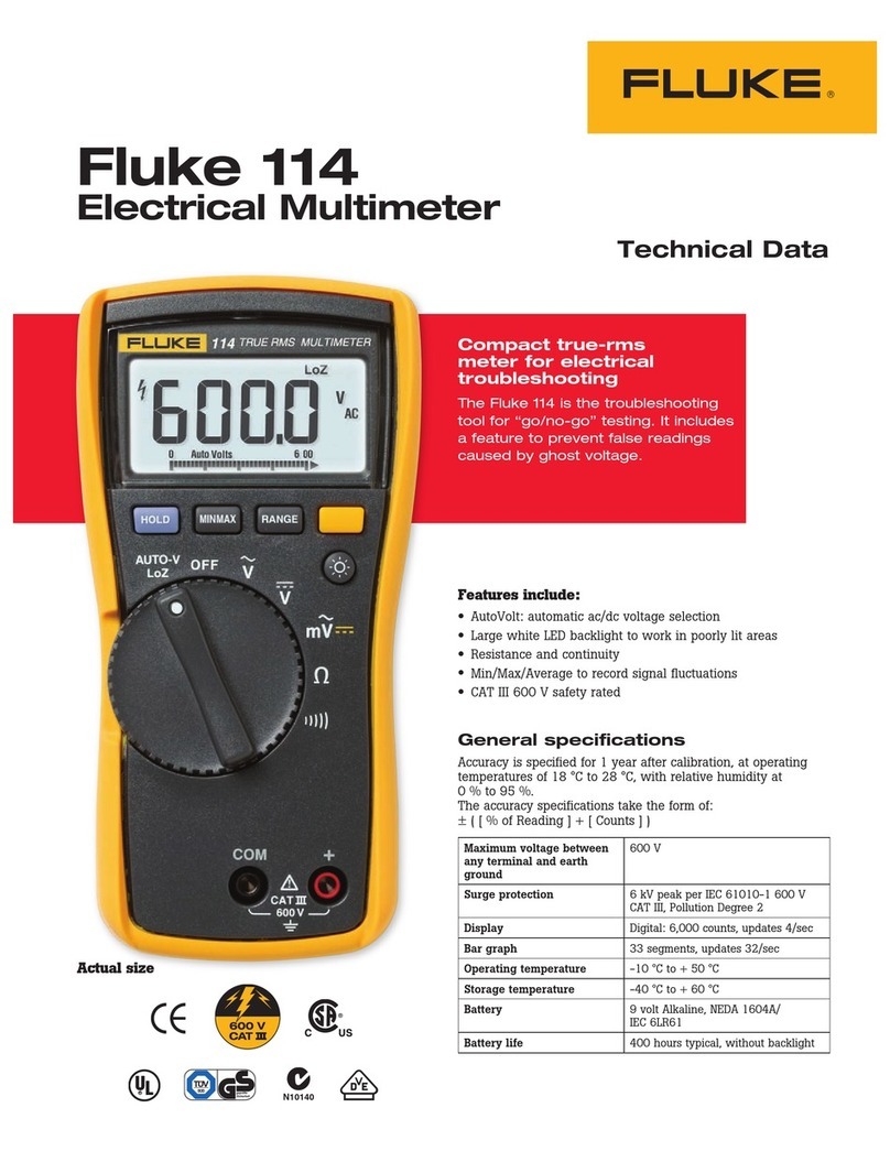
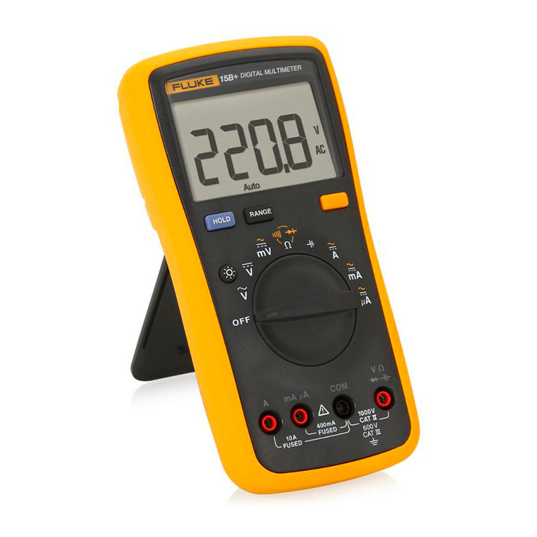
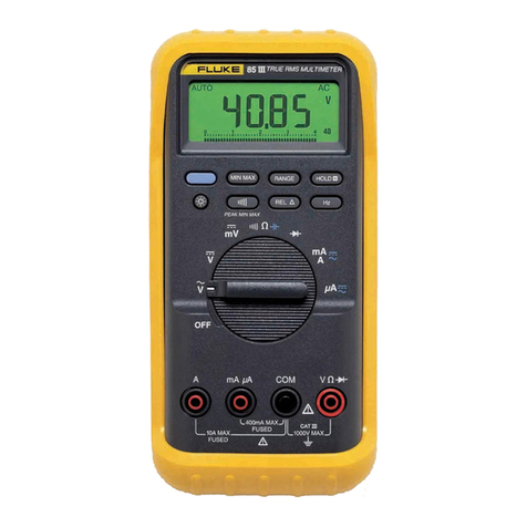
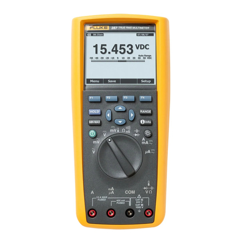
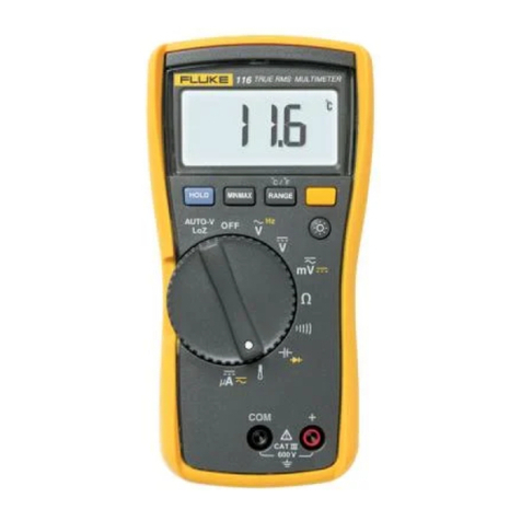
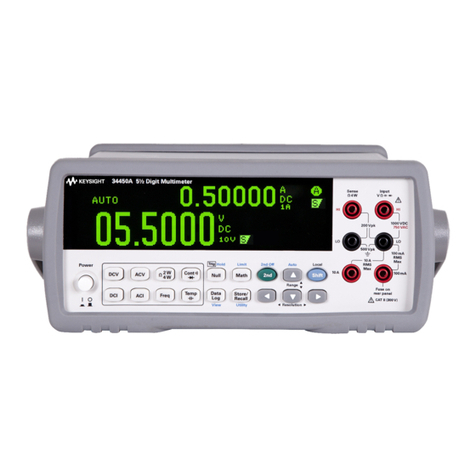
Fluke 27 User manual

®
27
Multimeter
Service Manual
For IEC 61010 CAT III Meters Only
PN 690206
November 1998 Rev.1, 9/03
© 1998,2003 Fluke Corporation, All rights reserved. Printed in U.S.A.
All product names are trademarks of their respective companies.


i
Table of Contents
Chapter Title Page
1 Introduction and Specifications........................................................ 1-1
1-1. Using the Meter Safely......................................................................... 1-3
1-2. Operating Instructions .......................................................................... 1-4
1-3. Specifications........................................................................................ 1-5
2 Theory of Operation........................................................................... 2-1
2-1. Introduction........................................................................................... 2-3
2-2. Functional Description ......................................................................... 2-3
2-3. Block Diagram Description.................................................................. 2-3
2-4. Input Overload Protection................................................................ 2-4
2-5. Function Switching Circuits............................................................. 2-4
2-6. Signal Conditioning Circuits............................................................ 2-4
2-7. Custom Analog IC (U1) ................................................................... 2-4
2-8. Peripherals to U1.............................................................................. 2-6
2-9. Microcomputer Control.................................................................... 2-6
2-10. Display.............................................................................................. 2-7
3 Maintenance........................................................................................ 3-1
3-1. Introduction........................................................................................... 3-3
3-2. Service Information .............................................................................. 3-4
3-3. Operator Maintenance .......................................................................... 3-4
3-4. Battery Replacement ........................................................................ 3-5
3-5. Fuse Test........................................................................................... 3-6
3-6. Fuse Replacement............................................................................. 3-6
3-7. General Maintenance Information........................................................ 3-7
3-8. Handling Precautions for Static-Sensitive Devices.......................... 3-7
3-9. Disassembly...................................................................................... 3-7
3-10. Reassembly....................................................................................... 3-10
3-11. Cleaning............................................................................................ 3-12
3-12. Performance Tests ................................................................................ 3-12
3-13. Display Test...................................................................................... 3-12
3-14. Voltage Functions Performance Verification................................... 3-13
3-15. AC and DC Current Performance Verification................................ 3-13
3-16. Ohms Function Performance Verification ....................................... 3-14

27
Service Manual
ii
3-17. Diode Test Performance Verification .............................................. 3-15
3-18. Calibration Adjustment......................................................................... 3-15
3-19. Calibration Preparation .................................................................... 3-15
3-20. DC Voltage Connection ................................................................... 3-16
3-21. AC Voltage Calibration.................................................................... 3-16
3-22. Troubleshooting.................................................................................... 3-17
3-23. Power-Up Self Test.......................................................................... 3-17
3-24. Overall System Check...................................................................... 3-17
3-25. DC Voltage Signal Tracing.............................................................. 3-18
3-26. Fault Diagnosis Guide...................................................................... 3-19
4 List of Replaceable Parts................................................................... 4-1
4-1. Introduction........................................................................................... 4-3
4-2. How to Obtain Parts.............................................................................. 4-3
4-3. Manual Status Information................................................................... 4-3
4-4. Newer Instruments................................................................................ 4-4
4-5. Service Centers..................................................................................... 4-4
4-6. Parts Lists.............................................................................................. 4-5
5 Schematic Diagrams.......................................................................... 5-1

iii
List of Tables
Table Title Page
1-1. Specifications......................................................................................................... 1-5
3-1. Recommended Test Equipment ............................................................................. 3-3
3-2. Replacement Fuses................................................................................................. 3-6
3-3. Ohm Function Performance Test........................................................................... 3-15
3-4. Fault Diagnosis Guide............................................................................................ 3-19
4-1. Final Assembly....................................................................................................... 4-6
4-2. A1 Main PCA......................................................................................................... 4-8
4-3. A2 Digital PCA...................................................................................................... 4-11
4-4. A4 Digital PCA...................................................................................................... 4-12

27
Service Manual
iv

v
List of Figures
Figure Title Page
3-1. Battery and Fuse Replacement............................................................................... 3-5
3-2. Disassembly ........................................................................................................... 3-8
3-3. Calibration Adjustment Locations......................................................................... 3-16
4-1. Final Assembly....................................................................................................... 4-7
4-2. A1 Main PCA......................................................................................................... 4-10
4-3. A2 Digital PCA...................................................................................................... 4-11
4-4. A4 Digital PCA...................................................................................................... 4-12
5-1. A1 Main PCA......................................................................................................... 5-3
5-2. A2 Digital PCA...................................................................................................... 5-7
5-3. A4 Digital PCA...................................................................................................... 5-7

27
Service Manual
vi

1-1
Chapter 1
Introduction and Specifications
Title Page
1-1. Using the Meter Safely......................................................................... 1-3
1-2. Operating Instructions .......................................................................... 1-4
1-3. Specifications........................................................................................ 1-5

27
Service Manual
1-2

Introduction and Specifications
Using the Meter Safely 1
1-3
1-1. Using the Meter Safely
Use the meter as described in this manual. Otherwise the safety features provided by the
meter might be impaired. A Warning identifies conditions and actions that pose hazards
to the user; a Caution identifies conditions and actions that might damage the meter.
Read First: Safety Information.
Read First: Safety Information
This meter complies with EN 61010-1:1993, ANSI/ISA S82.01-
1994 and CAN/CSA C22.2 No. 1010.1-92 Overvoltage Category
III. Use the meter only as specified in the Users Manual,
otherwise the protection provided by the meter may be
impaired.
XWWarning
To avoid possible electric shock or personal injury:
•Do not use the meter if it is damaged. Before use, inspect the
case for cracks or missing plastic. Pay particular attention to the
insulation surrounding the connectors.
•Inspect the test leads for damaged insulation or exposed metal.
Check test lead continuity. Replace damaged leads.
•Do not use the meter if it operates abnormally. Protection may be
impaired. When in doubt, have the meter serviced.
•Do not operate the meter around explosive gas, vapor or dust.
•Do not apply more than the rated voltage, as marked on the
meter, between terminals or between any terminal and earth
ground.
•Before each use, verify the meter’s operation by measuring a
known voltage.
•When servicing the meter, use only specified replacement parts.
•Use caution when working above 30 V ac rms, 42 V ac peak, or 60
V dc. Such voltages pose a shock hazard.
•Keep your fingers behind the finger guards on the probe when
making measurements.
•Connect the common test lead before connecting the live test
lead. Disconnect the live test lead first.
•Remove test leads from the meter before opening the battery
door.
•Make sure the battery door is closed and latched before operating
the meter.
•Use only a single 9 V battery, properly installed in the meter case,
to power the meter.

27
Service Manual
1-4
•Follow all equipment safety procedures.
•Before measuring current, check the meter’s fuses (see “How to
Test the Fuse”).
•Never touch the probe to a voltage source when the test leads are
plugged into the 10 A or 40 mA input jacks.
•To avoid false readings, which could lead to possible electric
shock or personal injury, replace the meter’s battery as soon as
the low battery indicator (M) appears.
•Avoid working alone.
•Remove all surface water from the product including water
around, within and under the rotary knob, input receptacles and
buttons prior to connecting to any voltages.
WCaution
To avoid possible damage to the meter or to equipment under
test:
•Disconnect the power to the circuit under test and
discharge all high voltage capacitors before testing
resistance, continuity or diodes.
•Use the proper function and range for your measurement
applications.
•When measuring current, turn off circuit power before
connecting the meter in the circuit. Remember to place the
meter in series with the current.
This manual presents service information for the Fluke 27 Multimeters. Included are a
theory of operation, general maintenance procedures, performance tests, calibration
procedures, troubleshooting information, a list of replaceable parts, and a schematic
diagram.
1-2. Operating Instructions
For operating instructions, refer to the Users Manual provided with the instrument at
time of purchase.

Introduction and Specifications
Specifications 1
1-5
1-3. Specifications
Instrument specifications are presented in Table 1-1.
Table 1-1. Specifications
Function Range Resolution Accuracy
F3.200 V
32.00 V
320.0 V
1000 V
0.001 V
0.01 V
0.1 V
1 V
±(0.1%+1)
±(0.1%+1)
±(0.1%+1)
±(0.1%+1)
l320.0 mV 0.1 mV ±(0.1%+1)
320.00
J
0.1
J
±(0.3%+3)*
3.200 k
J
0.001 k
J
±(0.2%+1)
J32.00 k
J
0.01 k
J
±(0.2%+1)
(nS) 320.0 k
J
0.1 k
J
±(0.2%+1)
3.200 M
J
0.001 M
J
±(0.2%+1)
32.00 M
J
32.00 nS 0.01 M
J
0.01 nS ±(1%+1)
±(0.2%+10)
ML 2.080 V 0.001 V ±(1%+1) typical
G40 Hz-2 kHz 2 kHz -10 kHz 10 kHz -30 kHz
3.200 V 0.001 V ±(0.5%+3) ±(2%+3) ±(4%+ 10)
32.00 V 0.01 V ±(0.5%+3) ±(2%+3) ±(4%+ 10)
320.0 V 0.1 V ±(0.5%+3) ±(2%+3) ±(4%+ 10)
1000 V 1 V ±(1%+3) ±(3%+3) Not Specified
I320.0 mV 0.1 mV ±(0.5% +3) ±(2%+3) ±(4%+10)
* When using the REL ∆function to compensate for offsets.
Function Range Resolution Accuracy Typical Burden Voltage
mN/A32.00 mA
320.0 mA
10.00 A
0.01 mA
0.1 mA
0.01 A
±(0.75%+2)
±(0.75%+2)
±(0.75%+2)
5.6 mV/mA
5.6 mV/mA
50 mV/A
c
µA 320.0 µA
3200 µA 0.1 µA
1 µA ±(0.75%+2)
±(0.75%+2) 0.5 mV/µA
0.5 mV/µA
d
mA/A
40-1000 Hz
32.00 mA
320.0 mA
10.00 A
0.01 mA
0.1 mA
0.01 A
±(1.5%+2)
±(1.5%+2)
±(1.5%+2)
5.6 mV/mA
5.6 mV/mA
50 mV/A
d
µA
40-1000 Hz
320.0 µA
3200 µA 0.1 µA
1 µA ±(1.5%+2)
±(1.5%+2) 0.5 mV/µA
0.5 mV/µA

27
Service Manual
1-6
Table 1-1. Specifications (cont)
Function Overload
Protection**
Input Impedance
(nominal) Common Mode Rejection
Ratio
(1 kJunbalance)
Normal Mode
Rejection
F1000 V rms 10 M
J
in // with <100pF >120 dB at dc, 50 Hz, or 60 Hz >60 dB at 50 Hz or 60 Hz
l1000 V rms 10 M
J
in // with <100pF >120 dB at dc, 50 Hz, or 60 Hz >60 dB at 50 Hz or 60 Hz
G1000 V rms 10 M
J
in // with <100pF
(ac coupled) >60 dB, dc to 60 Hz
I1000 V rms 10 M
J
in // with <100pF
(ac coupled) >60 dB, dc to 60 Hz
J1000 V rms Open Circuit Test
Voltage Full Scale Voltage
Up to 3.2 MJ32 MJor nS
<2.8 V dc <420 mV dc <1.3 V dc
** 107V Hz Max
Basic electrical accuracy is specified from 18°C to 28°C with relative humidity up to 95%, for a period of one year after
calibration. All ac conversions are ac coupled, average responding, and calibrated to read the true rms value of a sine wave
input. Accuracy is specified as ±([% of reading] + [number of least significant digits]).
Ranging is either automatic or manual in all functions with more than one range. Test resistance below approximately 270
J
in the
RG
function produces a continuous audible tone.
Maximum voltage between any
terminal and earth ground 1000 V
Fuse protection
mA or µA
A44/100 A 1000 V Fast
11 A 1000 V Fast
Digital Display 3200 counts, updates 2/sec
Analog Display 31 segments, updates 25/sec
Operating Temperature -15°C to 55°C, to -40°C for 20 minutes when taken from 20°C
Storage Temperature -55°C to 85°C without battery, to 60°C with battery
Electromagnetic Compatibility In an RF field of 2 V/m on all ranges and functions (except mVac),
total accuracy = specified accuracy + 1.0% or range. For mVac,
total accuracy = specified accuracy + 1.5% or range. EN 61326-1:1997.
Temperature Coefficient 0.1 x (specified accuracy)/°C (18°C or >28°C)
Relative Humidity 0% to 95% (0°C to 35°C)
0% to 70% (35°C to 55°C)
Altitude 2000 meters
Battery Type 9 V, NEDA 1604 or 6F22 or 006P
Battery Life 1000 hrs typical
Shock, Vibration and Water
Resistance Per MIL-T-28800 for a Style A, Class 2 Instrument
Size (HxWxL) 2.2 in x 3.75 in x 8 in (5.6 cm x 9.5 cm x 20.3 cm)
Weight 1.6 pounds (0.75 kg)
Waterproof 1 meter
Safety Complies with ANSI/ISA S82.01-1994, CAN/CSA 22.2 NO. 1010.1:1992 to
1000 V Overvoltage Category III. UL License pending to UL3111-1. TUV
License pending to EN61010-1.

2-1
Chapter 2
Theory of Operation
Title Page
2-1. Introduction........................................................................................... 2-3
2-2. Functional Description ......................................................................... 2-3
2-3. Block Diagram Description.................................................................. 2-3
2-4. Input Overload Protection................................................................ 2-4
2-5. Function Switching Circuits............................................................. 2-4
2-6. Signal Conditioning Circuits............................................................ 2-4
2-7. Custom Analog IC (U1) ................................................................... 2-4
2-8. Peripherals to U1.............................................................................. 2-6
2-9. Microcomputer Control.................................................................... 2-6
2-10. Display.............................................................................................. 2-7

27
Service Manual
2-2

Theory of Operation
Introduction 2
2-3
2-1. Introduction
This chapter describes how the Fluke 27 works. First, a functional description presents
an overview of operation. This is followed by a block diagram description, which
describes the major circuit functions in more detail. For reference, a detailed schematic
diagram is included in Chapter 5.
2-2. Functional Description
A block diagram of the Fluke 27 circuitry is shown in Figure 2-1. As this figure shows,
the instrument is composed of two major functional sections: the analog section and the
digital section. Each section contains one major active component and one or more
peripheral circuits. Most analog functions are performed by a custom analog IC (U 1)
and analog peripherals to U1. Digital functions are performed by a CMOS, 4-bit
microcomputer, U2.
The custom analog IC contains the A/D converter, signal conditioning circuits, and the
digital control circuitry required for communication with the microcomputer. Although
the custom IC is primarily analog, digital circuits provide state machine control for the
A/D converter, a read counter for A/D samples, decoding ROMs for analog switch drive,
and bus control for communication with the microcomputer.
The microcomputer controls the A/D converter, initiates the range and function
switching, formats data for display, and drives the display. The mode push buttons
supply input to the microcomputer to initiate various modes. Output from the
microcomputer is displayed on the liquid crystal display (LCD).
aac01s.tif
Figure 2-1. Overall Functional Block Diagram
2-3. Block Diagram Description
Each of the blocks in the Figure 2-1 is discussed in the following paragraphs. In many
cases, circuit sections are described in greater detail than is shown in the Figure 2-1;

27
Service Manual
2-4
therefore, it may be helpful to refer to the schematic located near the back of this
manual.
2-4. Input Overload Protection
Overload protection for the volts/ohms/diode-test input (J1) is provided by a network of
five metal-oxide varistors (RV1 through RV5) a current-limiting resistor (R2) and a
thermistor (RT1).
A 44/100A, 1000 V fuse provides protection for the mA/µA input (J2) current shunts. An
11 A, 1000 V fuse provides protection for the 10 A input (J3) current shunt. In addition,
for the µA and mA ranges, a bridge rectifier (U7) and four diodes (CR1, CR2, CR3,
CR4) ensure that the fuses (instead of the shunts) open in very high current overload
conditions.
Transistors Q1, Q2, and Q1 provide additional overload protection for the millivolt and
ohms functions. If sufficient overload voltage is present, the transistors turn on and
connect that input to common through limiting resistors R2 and RT1, thereby protecting
the circuitry in U1. A clamp circuit (CR6 and Q15) connected to the volt/ohms/diode-
test input through Z1 and C3 provides similar protection for the volts/ohms/diode-test
input.
2-5. Function Switching Circuits
Input signals are routed from the overload protection circuits to the function switch. The
function switch is a rotary switch with two double-sided wafers which provide the
necessary switching to select each of the various functions. In addition, battery voltage is
routed through the function switch from the battery voltage regulator to U1, and from U1
to U2.
2-6. Signal Conditioning Circuits
Each input signal is routed through signal conditioning circuitry before reaching U1.
Input signals received through the volts/ohms/diode-test input (J1) are routed through
Z1, a precision resistor network. The resistor network provides precise input scaling for
the various voltage ranges, and it provides precision reference resistors for the ohms
function. The capacitors in parallel with the various resistors in Z1 are used in the ac
voltage functions; the variable capacitors provide calibration adjustment for the high
frequency ac ranges.
Current inputs received through the mA/ µA input (J2) and the A input (J3) develop a
voltage across shunt resistors R14, R20, and R23 (320 µA, 32 mA, and 10 A
respectively). Resistors R9 and R10 comprise a 10:1 divider for the 3200-µA and 320-
mA current ranges.
2-7. Custom Analog IC (U1)
The analog-to-digital converter, autorange switching, and most of the remaining active
analog circuitry (including additional signal conditioning) are contained in U1, a custom
LSI package. Peripherals to U1 include the system clock, the reference voltage regulator
for the A/D converter, and some filtering and amplifier stabilization components. U1
also contains digital circuitry for state machine control over the A/D decoding ROMs for
analog switch drive and read counter preset, and registers to store control outputs from
the microcomputer.
Analog-to-digital conversion is accomplished within U1 using a modified dual-slope
A/D converter circuit, as shown in Figure 2-2. The conversion method in the Fluke 27
can be described as a charge-coupled, multiple-slope technique. A series of 10 minor

Theory of Operation
Block Diagram Description 2
2-5
conversions occur every 40 ms (each at 1/10th the desired resolution) without taking
time for an autozero phase between the conversions. These minor conversions (or
samples, as they are called in the following discussion) occur at a rate of 25 per second,
and are used to provided the fast response bar-graph display and fast autoranging.
New samples are taken every 40 ms. Ten samples are summed to produce a full-
resolution digital display, with full scale greater than 3200 counts. A 100 ms autozero
phase occurs every 10-sample sequence.
Basic A/D conversion elements and waveforms are illustrated in Figure 2-2. As this
figure shows, a residual charge is retained by the integrator capacitor due to the
overshoot past the true-zero base line. In the absence of an autozero phase, the residual
charge would normally produce a significant error in the sample next taken. However, a
digital algorithm eliminates the error and accounts for the residue as it propagates
through all 10 samples.
aac02s.tif
Figure 2-2. A/D Conversion Elements and Waveform
Digital circuitry in U1 provides state machine control for the A/D converter, a read
counter for A/D samples, decoding ROMs for analog switch drive and for read counter

27
Service Manual
2-6
preset, and bi-directional bus control for storing control outputs from the microcomputer
and for transferring data to the microcomputer.
Basic timing for the A/D converter is defined as a series of 10 integrate/read cycles
(samples), followed by a 100 ms autozero phase. However, the diode test and continuity
function, the 32 MJrange, the battery test, the power-up self test, overload recovery,
autoranging, and the Touch-Hold®mode all required variations from the basic timing.
The state machine, in combination with the ROM and preset read counter, plus an
autozero flag under computer control, establishes the timing variances necessary for the
various functions.
2-8. Peripherals to U1
Circuitry peripheral to U1 provides regulated battery voltage to power U1, a regulated
reference voltage for the A/D converter, a system clock, signal conditioning, and
amplifier stabilization. The battery voltage regulator consists of AR1, Q12, and
associated components; the regulator circuit supplies consistent operating power to U1
and, through a second regulator circuit in U1, to the microcomputer (U2). Voltage
regulator VR1 (and associated components) supplies a regulated 1.000 V reference
voltage for the A/D converter. Potentiometer R19 provides for calibration adjustment of
the reference voltage.
Additional circuits are necessary for the active filter, integrator, and buffer in U1. the
active filter response is determined by R13, R16, C18, and C19. Integrator and buffer
signal characteristics are determined by C20, C21, and two resistors in Z1. Several
components external to U1 provide for ac-to-dc conversion; they are C41, C42, C43,
R35, R7, C16, R30, R31, and R32.
The system clock, with a frequency of 32.768 kHz, controls all timing synchronization
for the instrument. Y1 is a quartz crystal which determines the frequency of the clock
oscillator circuit.
2-9. Microcomputer Control
A CMOS, 4-bit microcomputer (U2) controls the various instrument functions and drives
the LCD display. The microcomputer reads and processes data samples from the A/D
converter, sends a code to U1 which represents the operator-selected function, performs
the Touch-Hold algorithm, selects the correct A/D mode for the function in used,
controls range, sets the autozero flag, and disables the analog filter during autoranging.
In reading and processing A/D samples, the computer accepts raw sample data, applies
necessary corrections as described in the preceding discussion of U1, and accumulates
10 samples which then become the full resolution conversion for digital display. Each
minor conversion is also processed for the bar-graph display. For the diode test and
continuity function, the microcomputer evaluates the data and determines whether or not
the beeper should be switched on.
Touch-Hold operation requires the microcomputer to perform a different algorithm. The
microcomputer does not allow a full-resolution conversion to be completed unless the
input signal is stable. When a stable reading occurs, the conversion is completed and the
microcomputer generates the corresponding display and freezes it. the microcomputer
then waits for a change in the signal to exceed a certain threshold, and then begins
watching for a stable reading again. There are two exceptions to this simple algorithm:
First, open test lead indication does not allow a full-resolution conversion to be
completed either; the microcomputer continues to wait for a stable signal which is
outside the open test lead region. (Open test leads in voltage or current function result in
low readings; open test leads in resistance or diode test functions result in off-scale
Other manuals for 27
1
Table of contents
Other Fluke Multimeter manuals

Fluke
Fluke CNX 3000 Use and care manual

Fluke
Fluke 175 User manual

Fluke
Fluke 8012A User manual

Fluke
Fluke 789 Use and care manual

Fluke
Fluke 15B Use and care manual

Fluke
Fluke 106 User manual

Fluke
Fluke 110 Use and care manual

Fluke
Fluke Biomedical MPS450 Operators User manual

Fluke
Fluke 106 User manual

Fluke
Fluke 28 II Ex Parts list manual