11/09
CMT 130 Book Trimmer 1-3 Warning Label Definitions
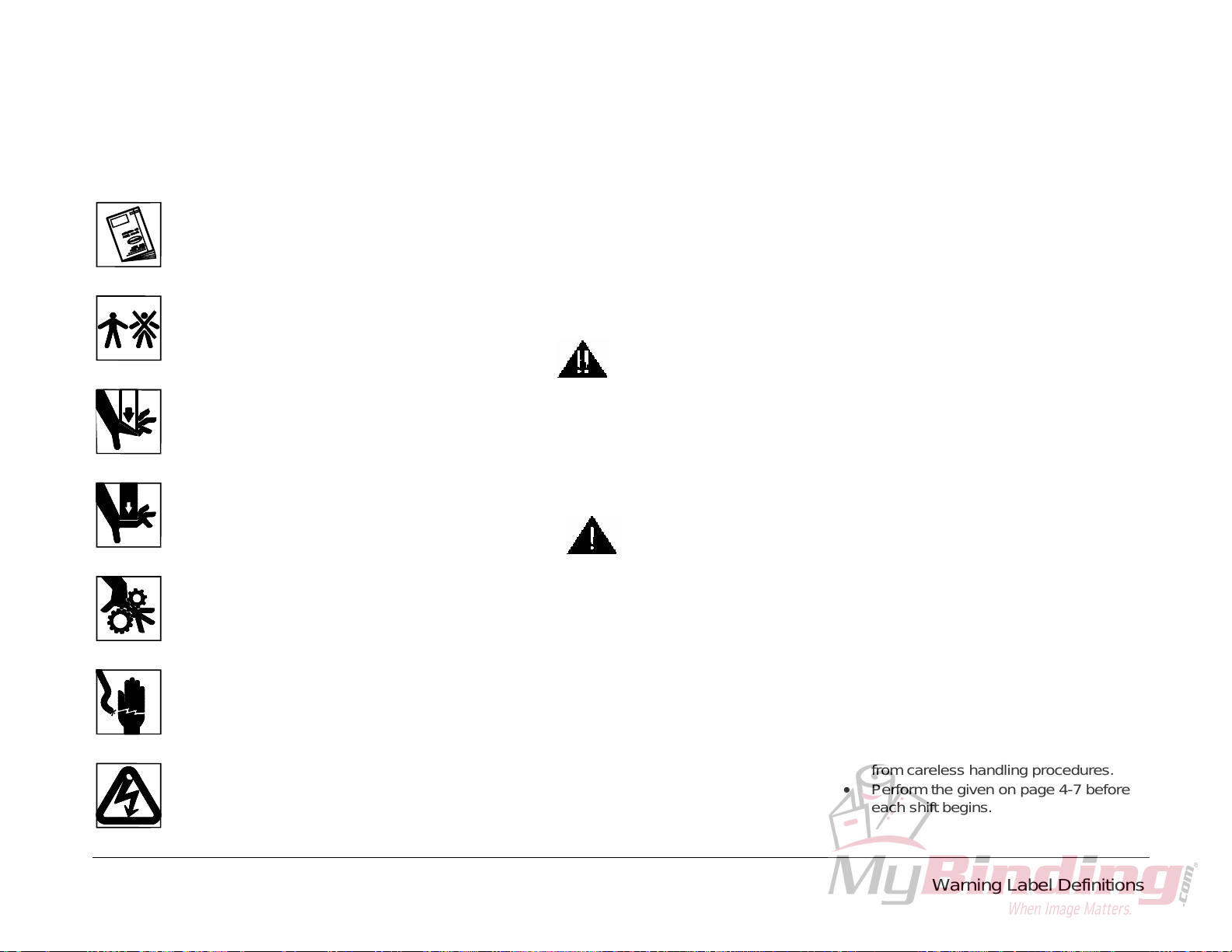
1.2 Warning Label Definitions
Warning labels are posted throughout the ma-
chine to indicate areas where physical injury
may occur.
Read the instruction manual.
The instruction manual should be
read and understood before operat-
ing this machine.
Do not operate with more than
one person!
One person only should operate
this machine at a time.
Cut / Crush Hazard!
Do not operate with covers re-
moved.
Do not disable safety devices.
Crush Hazard!
Do not operate with covers re-
moved.
Do not disable safety devices.
Crush / Entanglement Hazard!
Do not operate with covers or
guards removed.
Electrical Shock Hazard!
Disconnect power before removing
cover.
Electrical Shock Hazard!
Disconnect power before removing
cover.
1.3 Note Definitions
The formats of three specific types of notes
found throughout this manual indicate the level
of danger or importance associated with the
task presented. The format of warning notes,
caution notes, and regular notes imply a certain
level of danger. The following examples give a
description. Associate the text format with its
level of danger or importance.
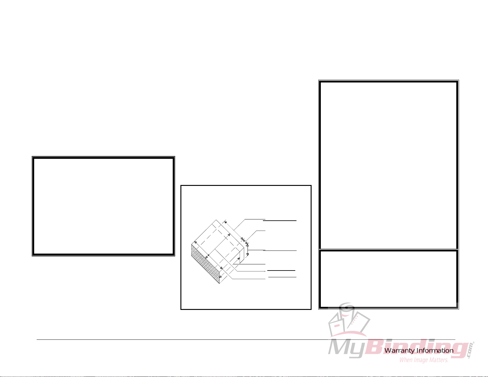
Warning Definition:
WARNING
A warning indicates an operating or maintenance pro-
cedure, practice, or condition that, if not strictly ob-
served, could result in injury or loss of life.
Caution Definition:
CAUTION
A Caution indicates an operating or maintenance procedure,
practice, or condition that, if not strictly observed could re-
sult in damage to, or destruction of, equipment.
Note Definition:
Note: A regular note indicates an operating or maintenance
procedure, practice, or condition that is necessary to ac-
complish a task efficiently.
1.4 Safety
Before installing or operating any equipment, it
is important to take precautions. Read and
thoroughly understand the safety precautions
outlined below.
•This machine is designed for one-
person operation. Never operate the
machine with more than one person.
•Safe use of this machine is the respon-
sibility of the operator. Use good judg-
ment and common sense when working
with and around the machine and its
accessories.
•Read and understand all instructions
thoroughly before using the machine. If
questions remain, contact your Author-
ized Challenge Dealer. Failure to un-
derstand the operating instructions may
result in personal injury.
•Only trained and authorized individuals
should operate this machine.
•Only trained and authorized service
technicians should service this ma-
chine.
•Do not alter safety guards or devices.
They are there for your protection. Se-
vere laceration or dismemberment may
result if safety devices are altered.
•Disconnect power and lock out before
performing any maintenance. See Sec-
tion 1.5 , Power Lockout Procedure.
•Observe all caution and instruction la-
bels on this machine.
•Be extremely careful when handling
and changing knives. Severe lacera-
tions or dismemberment could result
from careless handling procedures.
•Perform the given on page 4-7 before
each shift begins.