Mylaps RC4 User manual

ENGLISH
MANUAL
RC4
DECODER
PRODUCTCODE
40R248
VERSION 2.0

RC4 decoder V2.0. - October 2017 © MYLAPS rights reserved 2
Published by:
MYLAPS B.V.
Zuiderhoutlaan 4
2012 PJ Haarlem
The Netherlands
Copyright © 2017 No part of this document maybe reproduced by any means without the written consent of the publisher.
Whilst every care has been taken to ensure that the information in this document is correct, no liability canbe accepted by
MYLAPS for loss, damage or injury caused by anyerrors or omissions in this document. The sale of products, services of
publication is provided solely for informational purposes.
All hardware and software product names used in this document are likely to be registered trademarks and must be treated
accordingly.
Manual revision history
Version
Date
Amendments
Version 2.0
October 2017
Settings update for drone (DR5) use.
This device complies with part 15 of the FCCrules. Operation is subjectto the followingtwo conditions:
(1) This device may not cause harmful interference, and
(2) This device must accept any interference received, including interference that may cause undesired operation.
RF Exposure (OET Bulletin 65)
To complywith FCC RF exposure requirements for mobile transmittingdevices, this transmitter should only be used or
installed at locations where there is at least 20cm separation distance between the antenna and all persons.
This device complies with the EMC directive 2004/108/ECand RTTE directive 1999/5/EC. A copy of the declarationof
conformity canbe obtained at:
MYLAPS B.V.
Zuiderhoutlaan 4
2012 PJ Haarlem
The Netherlands
RoHS Compliant
This equipment has been tested and found to comply with the limits for RoHS compliant materials. These limits require
manufacturers to ensure thatthey do not use materialsor components that contain restricted substances that maybe
harmful to the environment.

RC4 decoder V2.0. - October 2017 © MYLAPS rights reserved 3
1. How to use this manual
Search for Keywords
Search for keywords such as to find a topic. Press Ctrl+Fon Windows or Command+F on Mac.
Navigate Topics
View a complete list of topics in the table of contents.Click on a topic to navigate to that section
Printing this Document
This document supports high resolution printing.
Legends
Hints and Tips Important Reference
Custom made
The Software Development Kit is a custom-made productby a third party.
About this Manual
This manual is intended foroperating andsupervisorypersonnel and provides information oninstalling and operating the
RC4 decoder.
This publication has beenwritten with great care. However, the manufacturer cannot be held responsible, either forany
errors occurringin this publication or for their consequences.
The sale of products, services of goods governed under th
Conditions of Sales and thisproduct manual is provided solely for informational purposes. This publication is to beused for
the standardmodel of theproduct type given on the cover page.

RC4 decoder V2.0. - October 2017 © MYLAPS rights reserved 4
Contents
1. How to use this manual .........................................................................................................................................................................................3
Legends.............................................................................................................................................................................................................................3
Custom made..................................................................................................................................................................................................................3
About this Manual.........................................................................................................................................................................................................3
Contents............................................................................................................................................................................................................................4
2. General..........................................................................................................................................................................................................................5
2.1. What is in the box.............................................................................................................................................................................................6
2.2. Specifications RC4 Decoder .........................................................................................................................................................................7
2.3. Installation of the RC Timing system........................................................................................................................................................8
Positioning the detection loop RC Racing.................................................................................................................................................9
Positioning the detection loop Drone Racing.......................................................................................................................................11
2.4. Operating the MYLAPS decoder..............................................................................................................................................................12
2.5. Noise level ........................................................................................................................................................................................................12
2.6. Signal strength................................................................................................................................................................................................12
2.7. Number of hits................................................................................................................................................................................................12
2.8. Firmware update............................................................................................................................................................................................12
2.9. The decoder.....................................................................................................................................................................................................13
2.10. Menu ................................................................................................................................................................................................................14
3. Appendix Auxiliary connections......................................................................................................................................................................17
4. Support.......................................................................................................................................................................................................................19
CE Declaration of Conformity MYLAPS RC4 - Decoder...............................................................................................................................20

RC4 decoder V2.0. - October 2017 © MYLAPS rights reserved 5
2. General
Next to Remote Control (RC)Racing, Drone (DR) Racing is a new type of sports.
We upgraded the most advanced RC and DRtiming system on the market; The RC4 system.
This system isbased on our RC4 system, that has been used in the world ofRC Racing for many yearsand still is thestandard
for timing RC races.
The RC4 system works with adecoder, detection loops thatare placed in and on (air) gates, timing software and DR5 and
RC4 transponders.
Every pilot owns or rents a lightweighttransponder that is mounted onto the drone. The transponder sends out aunique
signal, so there is no video signal erroring.When pilots register the transponder to their MYLAPS Speedhive account, they get
an overviewof all their training and race data.
When you already own a MYLAPS RC4 decoder, you can convert it towork with MYLAPS DR5 transponders through a
firmware update. Ask your account manager for this firmware update link.
This decoderwill not remove your RCtiming abilities, but your decoder will comewith an option to easily switch between
both disciplines.

RC4 decoder V2.0. - October 2017 © MYLAPS rights reserved 6
2.1. What is in the box
RC4 decoder including cabling.
RC4 decoder excluding cabling
External battery power cable 12 V
Lemo
15R003
15R002
30R103
For a basic setup, you need besides the decoder and transponders
Detection loop - 10 meter
Incl. coax cable - 20 meter
incl. coax cable - 50 meter
Incl. coax cable 100 meter
Detection loop 20 meter
Incl. coax cable 20 meter
30R001RC
30R002RC
30R003RC
30R004RC
Detection loop end box - 20meter
30R011RC
Software MYLAPS Practice
Custom madeby third party
The following components can be ordered from MYLAPS as part of RC4 Timingsystem
RC4 Upgrade
Ask your account manager
V4.5 upgrade for detecting DR5
transponders
DR5 Drone transponder
10R213
RC4 transponder
10R120
RC4 hybrid transponder
10R078
Detection loop end box 10 meter
30R010RC
Connection boxwith 20 m coax cable
30R020RC
Connection boxwith 50 m coax cable
30R021RC
Headphone
061099003

RC4 decoder V2.0. - October 2017 © MYLAPS rights reserved 7
2.2. Specifications RC4 Decoder
Dimensions
180 x 160 x 45 mm / 7 x 6.3 x1.8 in
Weight
720 g / 1.6 lb
Decoder Clockstability
0.5 ppm
Decoder Timing Resolution
0.001 s
Time of day clock stability (decoder off)
+/- 25 ppm
Time of day clock stability (decoder on)
+/- 0.5 ppm
Time of day clock resolution
1 sec.
Time of day clock synchronisation
via GPS receiver to UTC
Max. track width
max. 20 m / 66 ft
Operating temperature range
-20 to 50 C / -4 to 122 F
Humidity range
10 % to 90 % relative
Operating voltage range
10 to 14.4 V, typical 12V
Power consumption
max. 650 mA @12V, typical 500 mA
Interfaces
RS232, 9600 baud, 8 bits, 1 stopbit
RJ45,10/100 BaseT USB A
Network connection
DHCP client, APIPA, Static IP
Aux. Power
5 VDC, max 100 mA
Aux. Output
Opto coupled closing contact max 50 mA switched
Aux. Inputs
3x Opto coupled 5-12 VDC /5-15 mA
Compatibility
RC3, RC4,RC4 hybride and DR5 transponders.
Specifications are subject tochange without notice.

RC4 decoder V2.0. - October 2017 © MYLAPS rights reserved 8
3. Installation of the RC Timing system
The MYLAPS RC Timing System, is designed for the timingand scoring of RC model carraces and for Drone racing. The
(magnetic) signal of each car/drone carrying a MYLAPS RCtransponder ispicked up bythe detection loop installed in the
track surface. This loop is connected to the MYLAPS RC decoder. The decoder timestamps the received transponder signals
and sends thisdata to a connected computer.
Each transponder has a unique number, which enables you to identify and time/scoreeach RC car on the track.
The MYLAPS decoder is a precision instrument.Therefore,please handle it with care and keep the decoder out of direct
sunlight and avoid high humidity. Take special precautions in case of thunderstorms bydisconnecting all cables (coax,
Ethernet and mains) from the MYLAPS decoder. Nearby lightning strikes can damage the decoder when these cables are
connected.

RC4 decoder V2.0. - October 2017 © MYLAPS rights reserved 9
3.1. Installation RC4 system - RC Racing
Sport
Loopwidth
RC
30 cm (1ft)
To install the MYLAPS RC Timing System, one needs to install a detection loop, connect the decoder and mount the MYLAPS
RC transponders to the cars/Drone
Installation of the detection loop
All wiring of thedetection loop must be installed according to the drawings, to avoid a serious degradation in the
performanceof the system.
Positioning the detection loop RC Racing
1. The detectionloop mustbe positioned in such a way that the transponder is above the centre of the detection loop
when the front of the car is above the finish line. Make sure vehicles cannotpass outside the detection loop. Extend
the detection loop outside the track if necessary.
2. The detectionloop can be used for a track width of a maximum 10m (33ft).
3. Cut the slots in the track a maximum of 2cm (3/4inch) deep and 30cm (1ft) apart.
Installation of the detection loop wires and cabling For RC Racing
1. Make sure the slots are cleanand dry. This will ensure aperfect seal when the silicone is applied after installation of
the wiring. Put the wires of the detection loop in the slotsand cut theexcess length ofthe detection loop wires.
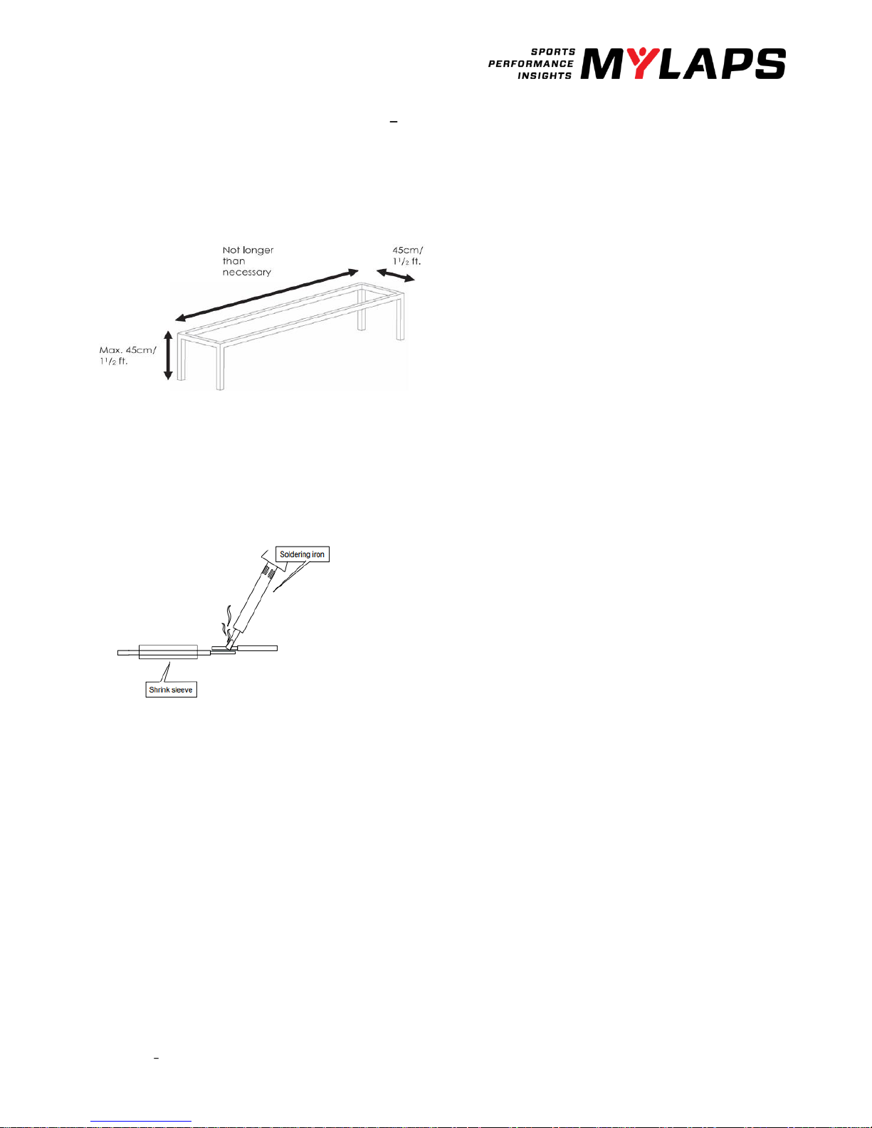
2. When all wiresare installed,put the heatshrinkage sleeve over a detection loop wire end. Then solder the loop wire
end to the short wire end of the connection box. When soldering the wires together, the solder should flow through
the entire connection and not only aroundit. Now putthe shrinkage sleeve over the soldered connection and hold
it over a heat source to shrinkthe sleeve (also see 5 the drawing on the next page). Repeatthis procedure for the
second wire end of the detection loop.
3. Fill the slot withsilicone. Make sure not to overfill the slots and that the silicone is fully under the surface of the track,
otherwise tiresmay pullout the silicone. If any silicone spills out of the slot, remove theexcess siliconeby scraping
the top with a small piece of cardboard. This also ensuresthat the silicone is pressed into the slot and into the sides
of the slot toensure a perfect seal.
There are a wide variety of silicone types available in hardware stores; it is important that the right type is used.
Silicone that canwithstand different temperatures as wellas both wet anddry conditions since weather situations
can vary should be used. If you are unsure,check the specifications of the silicone. The following types of silicone
have been shown to yield lasting results and are recommended by MYLAPS:
-levelling silicone kit. It is applied as a liquid and fills the slot completely.
x is a polyurethane-basedsilicone that retains its elasticity under a wide range of temperatures.
4. In the case ofan OFF-ROAD track, cover the loop with carpet or somethingsimilar. The carpet can then be covered
with sand. Please be awareof the max. distance of 15cm (6inch) between the transponder and the detection loop.
5. The detectionloop is sensitive to interference, sometimesemitted by nearby cables. When possible,keep other
cables 5m (15ft)away. Also make sure carson other parts of the trackwill not get closer than 5m (15ft) to the
detection loop, to avoid false inputs.

RC4 decoder V2.0. - October 2017 © MYLAPS rights reserved 10
Loop installation for temporary tracks For RC Racing
If slots for the loop cannot be made in the track, the loop can be fitted overhead on abridge. Do notmake this bridge of any
type of metalor carbon fiber, this will weakenthe signal severely.
1. Construct a bridge (wood,PVC) with max clearance 45cm (1.5ft) (lower isbetter). Donot make the bridge longer than
necessary. Make sure no cars can pass outside the bridge 8
2. Wires of the loop must be45cm(1.5ft) apart and fixed underneath the bridge. Put the connection box on top of the bridge.
Solder all connections and insulate well.
Please keep in mind that since a bridge has a larger distance between detection loop and passing transponder, thisresults in
a weaker signal for the decoder.
At dawn and atnight, the interference from short-wave radio signals intensifies stronglyand may occasionally cause the
transponder signals to get overwhelmed by the interference.To avoid this,keep the loop on the bridge as short (less than
3m (10ft)) and low as possible (less than 45cm (1.5ft)
Solder the loop wire end

RC4 decoder V2.0. - October 2017 © MYLAPS rights reserved 11
3.2. Installation RC4 system Drone Racing
Sport
Loopwidth
Drone
2.5 m x 2.5 m (8,2ftx 8,2ft)
Installation of the detection loop wires and cabling For Drone Racing
1. The detectionloop mustbe positioned in such a way thatthe transponder can go through the loop.
2. The detectionloop can be used in gateswith a maximumsize of 2,5mx 2,5m (8,2ft x8,2ft)
3. The detectionloop is sensitive to interference, sometimesemitted by nearby cables, LED bars or other
electronic devices. When possible, keep other cables/devices at least5m (15ft) away from the detection loop
4. For best performance MYLAPS recommendsusing non-metallic gates as these might also interfere with the
detection loop
3.3.Testing the detection loop installation
Once the loop has been installed, it shouldbe tested toensure thatit is functioningcorrectly. We also recommend repeating
the same procedure at the start of each raceevent. You can determine if your loop is functioning correctly by doing the
following tests:
1. Connect the detection loop to the decoder and computer running MYLAPS timing software. Check thebackground noise,
which is updated every 5 seconds in the MYLAPS timing software. The background noise level should bebetween 0 and 40
points. A higher value may indicate a bad loop installationor interference by other electrical equipment in the area. Try
switching offany suspected equipment orremoving nearby objects and check for improvements. Short-wave radio
transmitters may cause an increased background noise, especially at night.
2. Check the signal strengthsof the transponders as they are pickedup by the system during a test.A good loop will yield
consistent transponder signal strengths of at least 100 points with a hit rate of atleast 20 points. The hit rate mayvary
depending on the speed ofthe transponder passings (slower passings yield higher hitcounts), but thesignal strength
should be consistent for thesame car.
If noise is higher than 40 points, make sure that the signal strenghtof the transponderis at least 60points higher that the
noise level.

RC4 decoder V2.0. - October 2017 © MYLAPS rights reserved 12
4.Operating the MYLAPS decoder
The decoder is not equipped with an on/off switch, therefore connecting the decoderto the mainswill switch it on. This will
enable timingof transponder passings after approximately 15 seconds. With each detection of a transponder, a beep will
sound in the headphone andreceived transponder information is shown on the decoder display.
4.1. Noise level
The decoderdetermines theaverage background noise.
The background noise in combination withthe signalstrength is themost important indicator of the performance of the
hardware system. If a decoder is connected to the computer,the background noise willbe indicated inthe timelinestatus
screen.
The average background noiseis sent to the computer bythe decoder every five seconds.
Noise values:
0 The loop is notdetected
10-30 noise level is ok
30-50 noise level is medium
50+ noise level is high, not reliable detection.
If noise is higher than 40 points, make sure that the signalstrenght of the transponderis at least 60points higher that the
noise level.
4.2. Signal strength
Transponder signal strength,as shown by the timing software and on the decoder screen, shouldpreferablybe above 100
points and should at least be 60 points higher than the indicated background noise. The closer the transponder is to the
track, the higher the receivedsignal strength will be. A higher transponder signal strength should allow for greater immunity
against outside interference.
4.3. Number of hits
The number of hits, as shownby the software, is an indication of the number of repeated transponder signal receipts during
a passing. Hit-rates vary withthe speed ofa passing transponder. Slower passingsyield higher hit counts. Usually the number
of hits is greater than 10.
4.4. Firmware update
We constantly strive to improve all our products. For new functionalities andminor changes, you cancheck ourwebsite for a
MYLAPS decoder firmware update. Please go to the support section of thewww.mylaps.com website and follow the
instructions found there to download and install updated firmware as applicable.

RC4 decoder V2.0. - October 2017 © MYLAPS rights reserved 13
4.5. The decoder
Back side
1.
Detection loop
Connect the supplied 75 Ohm double-shielded coax cable tothe decoder.
2.
Auxiliary port
The auxiliary port has 3 inputs, photo cell 1, photo cell 2, sync pulse and a controlport for a GPS
receiver. For more informationon how to connect these devices, see appendix 4.
3.
Serial port
This port can be used to connect the decoderwith the computer through a RS232 cable.
4.
Network
This port can be used to connect the network cable between the decoder and the network
connection port of the computer.
5.
Power
Connect the supplied VDC adapter to the decoder and mains. It is recommended to connect the
VDC adapter tomains through a UPS (Uninterruptable Power Supply) toavoid any interruption of
power supply to the decoder.
Front side
1.
USB port
2.
Headphone
A beep willsound for every passing transponder, which provides an easy check for proper
operation of the decoder and the transponders on the track.
3.
Information display
Here you find the menu for setting up your decoder.
4.
Select button
5.
Acknowledgebutton
T -menu orselect the
highlighted option, depending on the situation.
1
2
3
4
5
1
5
4
3
2

RC4 decoder V2.0. - October 2017 © MYLAPS rights reserved 14
4.6. Information display status of the decoder
When the decoder is connected, this is the start screen ofthe information display.
1.
Decoder date/time, UTC when synchronized to GPS.
2.
Timeline name. S/F start or finish
3.
Blinks when connecting to Mylaps Practice,steady whenconnected to MYLAPS Practice
4.
Background noise indication
5.
Indication that hits are received, remains blackwhen a transponder is beingreceived by the loop.
6.
Strength of last received transponder.
7
Number of received GPS satellites.
8.
Links when GPS receiver attached, steady when decoder is locked to UTC time.
9.
Message line Youwill see errorsor warnings.E/g DNS error
4.7. RC4 decoder menu
By clicking on the acknowledge button you will cycle through the status screens:
•Active IP Address
•MAC Address/serial number
•Firmware version
•Stored passings
Main menu
By clicking on the Select and Acknowledge buttons you canchoose whichinformation youwant to see on the display.
Here you find all detailed information and the menu options.
Click on the select button to see the main menu.
With the selectbutton you go from top to bottom.
Timeline
General
Network
Data server
<<
1
2
3
4
5
6
7
8
9

RC4 decoder V2.0. - October 2017 © MYLAPS rights reserved 15
Sub menu
Click on the select button to go to Menu and click on the acknowledge button to go to the submenu. Click on the select
button to go to down in the menu. When yougot the right submenu, click on the acknowledge button again to set the
information.
Timeline
Name
Index
Main/backup
With these settings, you candefine the role of the decoder. The settings do not influence the decoder
performancebut can be retrieved by thesoftware for easier track setup. If multiple intermediatepoints
are used theIndex can be used to set the order of the intermediate points.
Squelch
With the squelch setting youcan suppress weak transponder signals. This is sometimesuseful if cars or
drones are near the loop or the coaxial cable andare picked up accidently. E.g. if the squelch setting is
set to 150 all transponderswith received strength below 150 will be ignored.
Car id Squelch
Time interval after the detection of a transponder, in which identical transponder numbers, but with a
different CarId, will not be detected. (Not applicable for RC4 compatible timingsoftware)
General
Decoder Mode
Choose if youwant to use drone or RC
Clear passings
Enables you to clear the passings in the flash memory.
Clock
Date: Here you canchange the date.
Time: Here you can change the time ofday.
To set your decoder to a specific time in seconds: First select the time in hours and minutes that you
wish to set thedecoder on. After this, the decoder will ask you to selectSET. At the exact momentSET
is selected, the decoder clockwill start at the selected time from zero seconds. Forexample: the new
time setting for the decoder is 11.15; whenyou press SET,the decoder clock will startcounting at the
exact time, 11h:15m:00s.
Beep
Choose the tone of the beep.
Protocol RS232
This is used toselect the protocol on the RS232 interface.Applies to both RC4 and DR5 transponders.
There are 3 options:
Enhanced - This protocol is hereonly for compatibility reasons. Not all features are available via this
protocol.
P3 - If you are a software developer this is the preferred protocol to use. This protocol is also used for
Remote - Allows the host computer to select the protocol by using a command. Use this setting when
used with Orbits.
Contrast
Contrast of the display - Hereyou can adjust the contrast settings.
Factory defaults
Reset to the factory defaults - You can reset the settings ofthe decoder to the initial settings.
Firmware
Software running inside thedecoder - Whenyou updatethe firmware in your decoder, the decoder
will retain the current version of the firmware. With the switch decoder firmware option you canrevert
back to the previous version.
Network
Please leave the decoder in the automaticmenu if you are not familiar withnetworkbasics.
Automatic
To automatically determine the IP addressof the decoder. If your decoder is placed ina network and
Configuration Protocol) to get an IP addresswhich is inthe range of the network. Please note that it
can take about 60 sec. to obtain the settings via DHCP. If aDHCP server is not found,the decoder will
use an IP address via APIPA(AutomaticPrivate IP Addressing).
IP Address
IP address ofyour decoder -An identifier for acomputer or device ona TCP/IP network.
Subnet Mask
A mask used to determine what subnet an IP address belongs to.
Gateway
A node on a network that serves as an entrance to another network.
DNS
Short for Domain Name System (or Service orServer),an Internet service that translates domain names
into IP addresses. Gateway and DNS are bothused to setup the decoder for MYLAPSPractice.

RC4 decoder V2.0. - October 2017 © MYLAPS rights reserved 16
Data server
This functionenables the decoder to contact aserver to upload data to. Contact MYLAPS for more details.
Enabled
Live upload toa data server is enabled.
Host
Host name orIP address ofa server to upload data to.
Port
TCP/IP port where the serverreceives the data.
MYLAPS Practice code
A unique code which shouldbe used for registering on MYLAPS Practice website
(www.mylaps.com/practice).Please visit mylaps.com for more information about onlinerace
results.
Note:
For accessing server functionality, you need a functioninginternet connection. Also, the DNSserver and gateway setting
must be correctly configured (see menuNetwork).

RC4 decoder V2.0. - October 2017 © MYLAPS rights reserved 17
5. Appendix Auxiliary connections
The MYLAPS decoder is equipped with an auxiliary port (15 pin sub D-connector).The auxiliaryport has 3 inputs, photo cell 1,
photo cell 2, sync pulse and a control port for aGPS receiver. All inputs canbe triggered by a 5 VDC (5-15 mA)pulse. Figure 1
explains the connection setup. To use aphotocell, connect it using the MYLAPS photocell cable or make an appropriate
cable using figure 1 below. Two types of photocells are available, passiveand active photocells. They both operate as a
switch; to connect the passive photocells please follow the connection setup in figure1a and scheme 1b. Active photocell
can be connected directly tothe photocell/sync and + input pins.

RC4 decoder V2.0. - October 2017 © MYLAPS rights reserved 18

RC4 decoder V2.0. - October 2017 © MYLAPS rights reserved 19
5. Support
In case you encounter any issues, please contact your sales offices:
Our Frequently Asked Questions (FAQ) canbe found on help.mylaps.com
MYLAPS EMEAOffice
Haarlem, The Netherlands
Tel: +31 23 7600200
Email: info@mylaps.com
MYLAPS Americas Office
Atlanta,USA
Tel: +1 678 816 4000
Email: info.americas@mylaps.com
MYLAPS Japan Office
Tokyo, Japan
Tel: +81 3 6418 8209
Email: info.japan@mylaps.com
MYLAPS Asia Office
Selangor, Malaysia
Tel: +60 3 5613 1235
Email: info.asia@mylaps.com
MYLAPS 24/7
Only in casesof direct needed support for event
organizers and companies.
Tel: +31 23 7600200

RC4 decoder V2.0. - October 2017 © MYLAPS rights reserved 20
CE Declaration of Conformity MYLAPS RC4 - Decoder
We,
MYLAPS
Zuiderhoutlaan 4
2012 PJ Haarlem
The Netherlands
Declare that the RF system
MYLAPS RC4 Decoder
In accordance with the followingdirectives:
2006/95/EC The Low Voltage Directive
2004/108/EC The Electromagnetic Compatibility Directive
1999/5/EC Radio & Telecommunications Terminal
Equipment Directive
Has been designed and manufactured to the following specifications:
EN 301-489-1 (2005-09)
EN 301-489-3 (2002-08)
EN 302-208-2 (2008-04)
EN 61000-3-2 (2006)
EN 61000-3-3 (2008)
I hereby declare that the product named above is designed to complywith the relevant sectionsof the above referenced
specifications, and all essential requirements of the Directives.
Name of authorizedperson: John Verwoerd
Function of authorized person: R &D Director
Place and Date: Haarlem, October, 2017
Signature ofauthorized person:
Table of contents
Other Mylaps Media Converter manuals