ASTRO U 158 User manual

U 158 8-way IP / QAM converter
U 100 - 230 Base unit
Operating manual

2
Operating Manual
U 158 8-way IP / QAM Converter
General
This operating manual was created to provide the relevant instructions for operating the
U158. We expressly recommend reading this manual before installing or operating the
device.
The ASTRO company confirms the information in this manual to be correct at the time of
printing, but it reserves the right to make changes, without prior notice, to the specifications,
the operation of the device and the operating manual. The ASTRO company is not responsi-
ble for printing errors. The contents of this operating manual are confidential and protected
by copyright. This manual may not be reproduced in any form - not even in part - without
prior written permission from the ASTRO company.
Pictograms and safety instructions
Pictograms are visual symbols with specific meanings. You will encounter the following pic-
tograms in this installation and operating manual:
Warning about life-endangering situations due to dangerous electrical voltage or non-
adherence to this manual.
Warning about various dangers to health, the environment or material.
Recycling: all of our packaging material (cardboard boxes, accompanying papers, plastic
film and bags) is completely recyclable.
Used batteries must be disposed of at approved recycling points. Batteries must be com-
pletely discharged before being disposed of.
Electronic devices must not be disposed of with household waste, but rather – according
to directive 2002/96/EG OF THE EUROPEAN PARLIAMENT AND OF THE COUNCIL from
January 27, 2003, on waste electrical and electronic equipment – must be properly disposed
of. When they are no longer of use, please bring these devices for disposal to one of
the public collection points for this purpose.
Copyright Notice
Parts of the software of this product is third-party software, which was developed under
several different licensing conditions. Detailed information concerning the licenses is provi-
ded using the webinterface of the device.
The source code of the free parts of the software is distributed on request for an admini-
stration fee.
Please contact:
ASTRO Strobel Kommunikationssysteme
Olefant 1-3
D-51427 Bergisch Gladbach (Germany)
Tel.: (+49) 2204 405-0
All other parts of the software of this product is Copyright by Astro Strobel Kommunikations-
systeme GmbH.
© Copyright 2011 by Astro.
2

3
Operating Manual U 158 8-way IP / QAM Converter
3
Table of contents
1 Figures....................................................................................................................4
1.1 Monitoring via rotary knob...................................................................................4
2 Introduction..............................................................................................................5
2.1 Description of functions .....................................................................................5
2.2 Safety instructions.............................................................................................5
2.3 Mounting instructions.........................................................................................5
2.4 Potential equalisation / grounding.......................................................................6
2.5 Maintenance and repair.....................................................................................6
2.6 Service tasks....................................................................................................6
2.7 Technical data for mains supply.........................................................................6
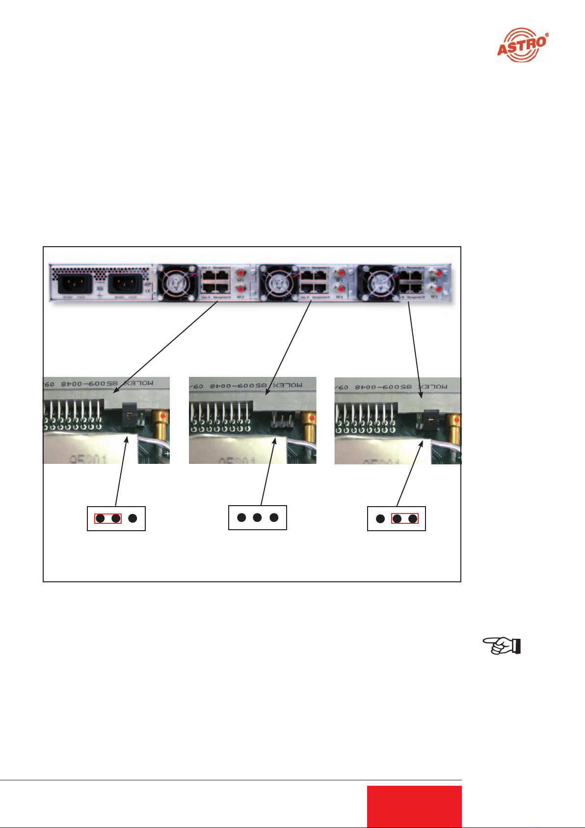
2.8 Installing and coding the backplane....................................................................7
2.81 Coding the backplane..............................................................................7
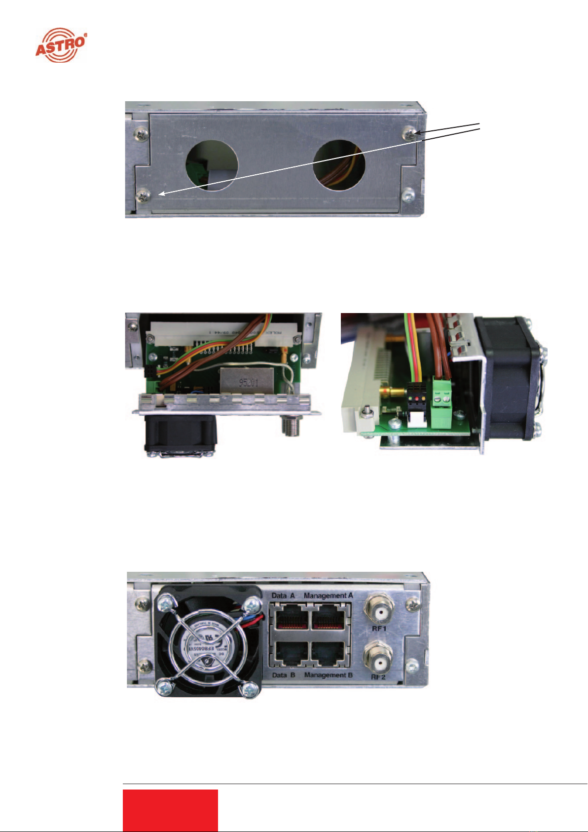
2.82 Installing the backplane............................................................................8
3 General introduction ..........................................................................................................9
3.1 Connecting the U 158 to a PC / laptop...............................................................9
3.2 The Web browser user interface.........................................................................9
4 Login................................................................................................................................10
5 Status...............................................................................................................................11
6 Settings for the IP interfaces, IP management and base device ...................................12
6.1 Configuration of the IP interfaces .....................................................................13
6.2 IP management configuration...........................................................................13
6.3 U 100 settings.................................................................................................14
6.4 Saving and loading a configuration, default and reboot .......................................14
7 Test generator .....................................................................................................15
8 Configuration of the IP inputs..................................................................................16
9 Configuration of the HF outputs...............................................................................18
9.1 Overview of the RF outputs...............................................................................18
9.1.1 Adjusting the output channel ..................................................................19
9.1.2 Level adjustment of the output channels.......................................................19
9.1.3 Operation with output channel filter...............................................................20
9.1.4 Configuration of the RF level detector...........................................................20
9.2 Detail adjustments of the QAM output channels.......................................................21
9.2.1 Modulation settings........................................................................................21
9.2.2 Processing the transport stream....................................................................22
9.3 NIT-Processing..........................................................................................................23
9.3.1 NIT-Remapping..............................................................................................23
9.3.2 Using a static NIT..........................................................................................23
9.3.3 Upload of a NIT .............................................................................................23
9.3.4 Generating a static NIT..................................................................................24
10 User management..................................................................................................25
11 Transport Stream (TS) Analyzer..............................................................................26
12 Licensing...............................................................................................................27
13 Software update / saving and loading a configuration ...............................................28
13.1 Update using example of a TFTP server for Windows .....................................29
14 System log............................................................................................................31
15 Statistics................................................................................................................32
16 Network properties.................................................................................................33
17 Logout ..................................................................................................................34
18 Technical data .......................................................................................................35

4
Operating Manual
U 158 8-way IP / QAM Converter
1 Figure
The figures show the U 158 installed in the U 100 - 230 base device.
1.1 Monitoring via rotary knob
After switching on the device, the boot action can be seen on the front display. The display swit-
ches off automatically after 1 minute without new message or without operating the rotary knob.
Pushing the rotary knob switches on the front display and turning the knob will change between
the different available views.
Display of network interfaces: Red: Interface switched on, but no link
Green: Interface switched on and available 100 MBit/s link
Turquoise: Interface switched on and available 1000 MBit/s link
Display of Logfile entries: Grey: Debug messages
Turquoise: Info messages
Green: Notice messages
Yellow: Warning messages
Red: Error messages
Violet: Critical, Alert and Emergency messages
Display of Service Status: First line: Channel name / channel frequency
Second line: Service name, if not switched off
Grey: Channel “Off”
Dark green: Ok, but switched to “Standby”
Light green: Ok
Status display
Control and data wheel, menu switch
Display of management IP addresses,
data IP addresses, status messages, etc.
Status display for slots
L = left
M = middle
R = right
P = power supply
4
Data ports HF outputs Fan
Management ports
Mains supply
Mains supply
Earthing connection
230 V Power supply:
48 V Power supply:
Fuse
Mains supply
Eaerthing connection

5
Operating Manual U 158 8-way IP / QAM Converter
5
2 Introduction
The instructions in chapter 2 mainly apply to the U 100 - 230 base device.
2.1 Description of functions
The U 100 series is used to convert IP data streams into CATV signals. The U 100-230 base
device can accommodate up to three U 1xx signal converters, as well as up to two U 100-SNTs
for supplying the voltage to the U 1xx signal converters. The U 158 receives up to eight video
data streams encapsulated according to the internet protocol (IP) and converts them into up to
eight standardised PAL output signals.
2.2 Safety instructions
Disconnect both mains plugs before opening the device!
The device must not be opened - for exceptions, see the maintenance and repair, and the service
tasks! Power supply units must not be opened!
The device must be connected to a power supply with an earth contact, and should be positioned
close to the mains socket.
The electrical system supplying current to the device, e.g. a house installation, must incorporate
safety devices against excessive current, short-circuiting and earth leakages in accordance with
EN 60950-1.
Both mains plugs are used to disconnect the device from the mains, therefore they must be easy to
access and use at all times. The device is already in operation when one power unit is connected
to the operating voltage. When the second power unit is also put into operation, one of the power
units runs in idle mode as long as the other unit is supplying power to the device. The device may
only be repaired by sending it to ASTRO along with a precise description of the error.
Displays indicate the status of the device operation, as well as the existence of DC voltages
separate from the mains that are supplying the components of the device. However, operation
displays that are not lit up in no way indicate that the device is completely disconnected from the
mains or is voltage-free.
Read carefully:
EN 50 083 – Part 1, Safety requirements / No service tasks during electrical storms!
2.3 Mounting instructions
The U 100 base device may only be mounted using guide rails! If the device is only fastened by
means of the screws in the front panel, this will damage the base device!
The outputs of the signal converter must not be operated without connecting a combining network
or terminating impedance!
Protection from environmental factors:
The device must only be connected and operated in dry rooms. It must not be exposed to spra-
ying or dripping water, or to similar phenomena. If condensation appears, wait until the device is
completely dry. Objects containing liquid must not be placed on top of the device.
The permitted ambient temperature range is 0 … 45°C (ETS 300 019-1-3 class 3.1).
Mounting environment:
The device is designed for operation in, preferably, metallically conductive 19“ racks with sufficient
air convection. It should be operated away from heat radiation and other heat sources. The
device my only be installed in rooms in which the permitted ambient temperature can be adhered
to, even under changing climatic conditions. To avoid trapped heat, it must be freely ventilated
on all sides. You absolutely must avoid mounting the device in a niche or covering the ventilation
openings.

6
Operating Manual
U 158 8-way IP / QAM Converter
6
2.4 Potential equalisation / grounding
The subscriber network must be grounded correctly in accordance with EN 50083-1, and must
remain grounded even when the device is removed.
The potential equalisation on the U 100 is effected via the fastening plates of the device, or
via the grounded connection on the back of the device. Devices within hand‘s reached must be
incorporated into the potential equalisation among one another.
It is not permitted to operate the device without an ground conductor, device grounding or
device potential equalisation!
2.5 Maintenance and repair
Disconnect both mains plugs before opening the device!
The device must not be opened other than for repair purposes. In general, power units must
not be opened. Repairs may only be carried out at the plant or at workshops, or by persons, aut-
horised by ASTRO Strobel Kommunikationssysteme GmbH.
Read carefully: DIN VDE 0701- 0702, Repairs
Note: The device must not be opened by the user!
2.6 Service tasks
The following tasks, in which screw connections have to be opened, can be performed by appro-
priately instructed service personnel: removal and installation of signal converters (e.g. U 158)
and power units, also in the operating mode of the U 100.
Replacing power units
After the screws on the cover of the power unit chamber (ASTRO logo) are removed,the power
units can be pulled out by hand, forwards along the mounting panel. When power units are being
installed, there should be no contact with the ventilator or the fan grid,
and only the mounting panel attached to the power unit should be used.
When the tasks are complete, the cover of the power unit chamber must be replaced;continuous
operation of the device is not permitted without this cover.
Note: Do not put your hand or any objects into the power unit chamber.
The U 100 must only be operated with the original power unit(s)!
Replacing converter modules:
Converter modules can be pulled outwards after the safety screw on the front panel has been
unscrewed.
2.7 Technical data for the mains supply (U 100 SNT 230 V version)
Mains voltage: 100 – 240 V
Mains frequency: 50 / 60 Hz
Current consumption: 1.4 – 0.7 A per power unit
Protection class according to EN 60529: IP 20
Permitted ambient temperature range: 0 … 45°C
Secondary fuse in U100-230: T3,15A L 250 V IEC 60127-2/3
Secondary fuses in U158: SMD, various values

7
Operating Manual U 158 8-way IP / QAM Converter
2.8 Installing and coding the backplane
The scope of delivery of every U 1xx signal converter includes a backplane to create the physical
connection between the signal converter and the base device. Both the mains HF connections
and the network connections are connected to this backplane. The temperature controlled fan for
cooling the U 1xx signal converter is located on the backplane.
2.8.1 Coding the backplane
To correctly define the position of the backplane, and thus the position of the related signal con-
verter in the U 100 base device, the jumper on the board of the backplane, which is described in
the following section, must be configured.
Figure 1: Coding the backplane using the jumper
Note:
An incorrectly configured jumper leads to incorrect displays in the front LEDs.
Additionally, it is not possible to display a correct position on the Web user interface!
7
Jumper position
left!
Left RightMiddle
Jumper position
right!
No jumper!

8
Operating Manual
U 158 8-way IP / QAM Converter
2.8.2 Installing the backplane
In its state on delivery, the back of the U 100 base device is covered with blind panels:
Figure 2: Position of the blind panel on delivery of U 100
To remove the blind panel, unscrew the two Phillips screws indicated in the above figure and
remove the blind panel. The cables now visible must be connected to the backplane coded accord-
ing to chapter 2.8.1, as shown in the following figure:
Figure 3: Connecting the voltage supply and signal lines
The backplane is now carefully inserted into the free slot of the U 100 base device and screwed in
with the Phillips screws of the backplane. Here you must ensure that the cables are not jammed and
that the backplane can be installed in the housing with only a small amount of pressure.
Figure 4: Correctly installed backplane
8
Phillips
screws

9
Operating Manual U 158 8-way IP / QAM Converter
9
3 General introduction
3.1 Connecting the U 158 to a PC / laptop
When the operating voltage is connected, or after it is inserted into the slot of the base device,
the U 154 switches on automatically. After the boot phase (ca. 90 seconds), will be displayed
status messages.
If the device is connected to a PC / laptop via one of the network ports, and if the PC / laptop is
suitably configured via the network settings, after you enter the IP address in the address line
of the Web browser you can start configuring the U 158 .
3.2 The Web browser user interface
The Web browser user interface is divided into the top frame, the left frame and the main frame.
The top frame contains general information about the U 158 .
This information is as follows:
“SW: 4419” indicates the software level of the U 158 EdgeQAM,
“FW: 1.8” is the level of the firmware in the U 158 EdgeQAM,,
“HW: 4” is the hardware version of the U 158 EdgeQAM,,
“Up: 0d 21h 25m 51s” is the duration of the connection, measured from the moment of the login,
“Time (UTC):” displays the time of the U 158 .
The line in bold for the “name”, “location” and “contact” is made up of the settings in the “User”
chapter.
In the right section of the top frame, status information for the U 158 is displayed, i.e. in the Web
browser user interface, the latest error message is visible.
The left frame
contains the navigation bar for the various submenus, which are described in detail in the follow-
ing chapters.
In the main frame,
the submenu is displayed according to the selection made in the navigation bar in the left frame.
Figure 1: General information in the top frame of the Web browser user interface
Figure 2: View of U 158 Display of the Web browser user interface

10
Operating Manual
U 158 8-way IP / QAM Converter
10
4 Login
Before the U 158 can be configured there must be a login. This is performed in the “Login” sub-
menu.
In the state on delivery, the login data is as follows:
User: admin or user
Password: astro
After correctly entering the login data, you can proceed with the configuration.
Note:
For security reasons, the user names and passwords should be changed from the state on deli-
very. This prevents unauthorized access.
Only one user / BC 4 can ever be logged into the U 158 . At the very bottom of the left frame of
the Web browser user interface, the user currently logged in is displayed.
Figure 3: Users Log-in / Controller Log-in
Display of the
Users / Controller Log-in

11
Operating Manual U 158 8-way IP / QAM Converter
5 Status
When you click on the “Status” submenu in the left frame, the following window appears (example)
Figure 4: Status display in the “Status” submenu
11
Ethernet status
Status display of
the IP receivers
Memory status
Status display
of the HF output
channels
Display of diverse
status messages on
the module tempera-
ture, the internal vol-
tages and the power
unit status
Here all the relevant
data for the status of
the U 158 is displayed
in detail. No settings
can be made here.

12
Operating Manual
U 158 8-way IP / QAM Converter
12
6 Settings for the IP interfaces,
IP management and base device
When you click on the “Main” submenu in the left frame, the following window appears (example):
Figure 5: Overall view
The settings available are described in detail in the following sections.

13
Operating Manual U 158 8-way IP / QAM Converter
13
6.1 Configuration of the IP interfaces
In the area of the user interface displayed below you can activate and deactivate the IP interfaces.
The connection type is automatically detected and displayed by the U 158 .
(Here: 1 GBit/s, full duplex for Data A&B and 1 GBit/s, full duplex for Management A&B).
Figure 6: IP interface configuration
Changes in the IP addresses can only be done by the admin (account 1 in the user administration,
see chapter 10). Those changes have to be transferred to the device using the “Submit” button.
After the successful change of IP settings a re-login is required.
Note:
When programming the IP addresses, make sure that the addresses are not already allocated in
your network. Address conflicts lead to malfunctions in the network. Unused network interfaces
must be switched off. Before allocating the IP addresses, it must be ensured, that interfaces con-
nected to different network segments are not located in the same subnet.
6.2 IP management configuration
In the IP management configuration, the DNS server and the SNTP server are entered. If a valid
entry is made under “SNTP server”, this can be used as a time reference. The MPEG streams
(TDT) are additional time references. If the U 158 is configured via U 100-C controller, this con-
troller can be used as SNTP server as well.
Figure 7: IP management configuration

14
Operating Manual
U 158 8-way IP / QAM Converter
14
6.3 U 100 settings
Under “U 100 Rack Settings” an address can be allocated to the relevant base device. This setting
affects all other signal converters in the base unit. The number of the currently selected slot is
displayed below it:
Figure 8: Rack Settings
6.4 Saving and loading a configuration, default and reboot
The current configuration of the U 158 is always written to the device using the “Submit” buttons,
and is therefore activated immediately. If you want to save the current status, you press the “Save
2nd” button. This current status is then saved on the SD card in the U 158 . You can call up this
status again using the “Load 2nd” button. Saving the configuration on the local computer or FTP
server is explained in the “Update” chapter.
Figure 9: Saving and loading / default and reboot
The “Default” button is used to restore the factory settings.
Note:
With the factory settings, all the settings apart from the user and network settings of the data and
management ports are reset to the state on delivery!
The “Reboot” button restarts the U 158 with the last settings that were entered.

15
Operating Manual U 158 8-way IP / QAM Converter
15
7 Test generator
The U 158 has an integrated test generator for checking the functions of the QAM modulators
when no input signal is available yet. The max. data rate that can be set is 67 MBit/s.
Figure 10: Test generator settings
If you choose the testgenerator at “ service” in the RF settings, the QAM modulator generates
digital radio programm with a 1 kHz tone.

16
Operating Manual
U 158 8-way IP / QAM Converter
16
8 Configuration of the IP inputs
When you click on the “IP RX” submenu in the left frame, the following window appears (example):
Figure 11: Overview of the IP input configuration
Here the four IP inputs to be configured are activated or deactivated, and their current configura-
tion is displayed. You go to the detailed settings either by clicking the relevant channel (e.g. IP
RX3) or clicking the relevant submenu in the left frame.
Figure 12: Detailed settings of the IP receiver
To enable the greatest possible path redundancy, the U 158 has various different configuration
options for the IP receivers. The Data A and Data B ports can be configured completely indepen-
dently of one another. IGMPv3 enables what is known as “Source Select”, i.e. the IP receiver can
request the data from a preferred source.

17
Operating Manual U 158 8-way IP / QAM Converter
17
Figure 13: Setting the Multicast addresses
The “use” selection box defines the data source used. This data source is defined via the Multicast
address and can - if this Multicast address is provided by multiple senders - be used preferentially
by the IP receiver. The IP address of the preferred source is entered under “Primary / Secondary
Source Select”. If 0.0.0.0 is displayed here, the Source Select function is deactivated.
If different signal paths are supplied by the same sending equipment, it can make sense to confi-
gure Data B exactly like Data A. This is easily performed by activating “like Data A”.
Figure 14: Settings for the IP input signal format
In the “Enable” line, the IP receiver is activated or deactivated. In the “Port” line, the data interface
is selected (A or B) and the preferred data interface is set. This function enables the U 158 to
switch to the second interface after an input signal has failed, and to switch back when the failed
signal has been re-established (prefer A or B). If you select the “auto” option, the IP receiver
remains on the substitute interface until it is manually switched back, or until this interface fails.
Under “Encapsulation” the protocol used in the sender is set: RTP/UDP/IP or UDP/IP. However,
the U 158 is also able to detect the protocol automatically and evaluate it accordingly.
For the “Bitrate” you can choose between “Single PCR (SPTS)” and “Multiple PCR (MPTS)”. Here
the U 158 can also detect the status automatically and process it.
To have a better overview during the configuration of the HF parameters, you have the option of
entering an alias. If this entry option is not used, the first service in the transport stream is auto-
matically used as the alias.

18
Operating Manual
U 158 8-way IP / QAM Converter
18
9 Configuration of the HF outputs
9.1 Overview of the RF outputs
By clicking to the submenu „RF“ in the leftframe, the overview of the RF parameters will be dis-
played
Figure 15: Overview of the RF parameter
On this page the output channel can be activated and deactivated. By chosing the option „Stand-
by“ in the column „Enable“, only the RF will be switched off. The configuration of the output signal
remains active as well as the analysis of the input data stream.
In the column „Stream“, the choice of the input signal to be converted will be done. By opening
the dropdown menu, all available services received by IP RX 1 to IP RX 8 are displayed. The last
possible option to choose from is the ASTRO test generator, which creates a digital radio program
with a 1 kHz tone in the adjusted output channel.
Figure 16: Dropdown menu for stream selection

19
Operating Manual U 158 8-way IP / QAM Converter
19
In the column „Symbol Rate“, the configured symbol rate of the output channels are displayed.
Further information concerning the output channel are shown in the column „Standard Bandwidth
Constellation TS Rate“. This information is: QAM Standard, the bandwidth of the output channel,
the type of modulation and the output data rate.
9.1.1 Adjusting the output channel
The setting of the output channel is done in the column „Channel Frequency“. Here, pre-program-
med channels can be chosen from the channel list. If a value from this list is chosen, the direct
frequency insertion remains inactive and the corresponding channel frequency will be displayed.
If the option “manual” is chosen, the channel frequency can be typed in manually.
Note:
Inside one pair of channels (RF 1.1 / 1.2 / 1.3 / 1.4 or RF 2.1 / 2.2 / 2.3 / 2.4), 32 MHz can be set
between the start frequency of channel RFx.1 and the endfrequency of channel RFx.2. Example:
RF 1.1 = S06 und RF 1.2 = S09 at a channel bandwidth of 8 MHz. If this gap becomes too big,
the following error message will be generated:
Figure 17: Error messages occurring at too high gap between output channels
The affected output channel will be set on „Standby“ and must be re-activated after a correctly
set configuration. If a gap between two output channels will be programmed, it is not possible to
use output channel filters.
9.1.2 Level adjustment of the output channels
The level adjustment of an output channel takes place in the column „Level“. The level is adjusted
in 0.1 dB steps relatively to the absolute output level. Changes in the level adjustment are activa-
ted by clicking the “Submit” button. The adjustable range depends on the set QAM modulation:
QAM 64 up to +10 dB, QAM 256 up to +4 dB). If the adjusted level will exceed the allowed range,
the following warning message occurs:
Figure 18: Warning message at inadmissible level adjustment
After an closing this window via „OK“ button, the maximum value will be set. This maximum value
will become active after using the button „Submit“.
Note:
If the QAM modulation of an output channel pair will be changed, the level will be adapted auto-
matically.

20
Operating Manual
U 158 8-way IP / QAM Converter
9.1.3 Operation with output channel filter
If an output channel filter (U-KF…) is plugged to the U 158, this channel filter will be recognised
by the device. This leads to the activating of the option „Channel filter On / Off“. If no filter is
assembled, this option remains inactive. To finally activate the channel filter, both configurable
limits of the output channel filters must be in the same range as the programmed output channel
of the U 158, shown in the column „Channel Frequency“. Of course the filter limits can be different
to the actually programmed output channels, but in that case the output channel filter can not be
activated.
9.1.4 Configuration of the RF level detector
The U 158 is equipped with an output level detector. This detector permanently measures the
output level. By using the button “Set” in the column “Reference”, the actual level will be set as
reference level. A possible deviation of this reference level will be displayed. Eventual occurring
deviations can lead to different configurable actions. These actions can be set in the area below
“RF Detector”:
Figure 19: Configuration of the level detector
If the deviation is in a range between +/- 2,5 dB a warning can be activated, which will lead to
an entry in the Logfile. Depending on the SNMP configuration this can lead to a trap as well.
The next step would be a security switch off of the output channel, affected by a level deviation
of + 3 dB. To enable this action, the option “security switch off” must be set to “on”. If the option
„Lock RF relevant settings“ is activated, only the stream to be converted can be changed at „RF
channels“. All other adjustments in this submenu are locked in that case. Beyond this, all possible
configurations concerning the RF output channel in the modulation settings are locked as well
(RF 1.1 to RF 2.4).
20
Other manuals for U 158
1
This manual suits for next models
1
Table of contents
Other ASTRO Media Converter manuals